See if this sounds familiar—the gas gauge on your hot rod reads full seemingly forever then the needle suddenly plummets to E, usually after you've gone a few miles past an offramp to a convenient gas station. Of course an unreliable gas gauge can manifest itself in any number of ways. It may indicate there's more fuel in the tank than there is or it may show less, or it may not work at all. In any case having to compute how many miles you've traveled since you last topped off the tank is not a fun way to travel and often causes more fuel stops than necessary, or in the worst case scenario, one less than needed.
Regardless of how an inaccurate gas gauge manifests itself, the cause is often a lack of compatibility between the gauge and the sender. In operation current passes through the gauge then onto the sender, which completes the circuit to ground. As the fuel level goes up or down, a float connected to an arm on the sender causes the electrical resistance to change increasing or decreasing the current flow through the gauge, which causes the indicator needle to move. While that sounds simple enough, for reliable readings the gauge and the sender must operate on the same range of electrical values. As an example, if the sender has a resistance of 240 ohms when the tank is empty and 33 ohms when full, the gauge must have the same range. That sounds simple enough in principle, but the hot rodding practice of mixing and matching components often means that the relationship between the sender and gauge goes out the window.
In the past there haven't been any truly effective methods to correct mismatched gauges and senders, but thanks to Classic Instruments there is now, it's called the Fuel Link. This little black box of electrical magic corrects the resistance mismatch between gauges and senders, allowing virtually any combination to work properly. In addition, it will eliminate erratic gauge readings due to fuel slosh. The Fuel Link comes with eight preset ohm ranges (empty to full) 240-33; 0-90; 0-30; 16-158; 75-10; 90-0; 10-180; 40-250—in addition custom calibrations between 0 and 350 ohms can be made.
Classic Instruments' Fuel Link is an affordable, effective means of making mismatched gauges and send work together. For the utmost in accuracy Fuel Link calibrates the gauge at every 1/4 tank reading. Easy to install, the Fuel Link is compact at 3x2x1.5 inches, there are individual screw terminals for connecting the wires, and a push button and LED readout for calibration. Another really cool feature is the Low Fuel Light trigger at 1/8 tank (works with an LED or incandescent bulb).
Gas Gauge Tips From Classic Instruments
Always include an extra ground from the top of the sending unit to the chassis; tanks are normally installed with isolators of some sort between the mounting brackets and the frame that also serve as electrical insulators.
Test the sending unit before installation. With the ground and sending unit wires attached have a helper turn the key to the run position to power up the instruments then swing the float to top—the gauge should read full, swing the float to the bottom of its travel, and the gauge should read empty.
When adjusting the float at the bottom of its travel Classic Instruments recommends leaving a little reserve in the bottom of the tank, so when the instrument reads empty you have a ½-gallon or so left in bottom as "get to the exit fuel."
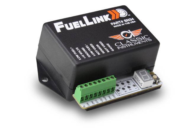
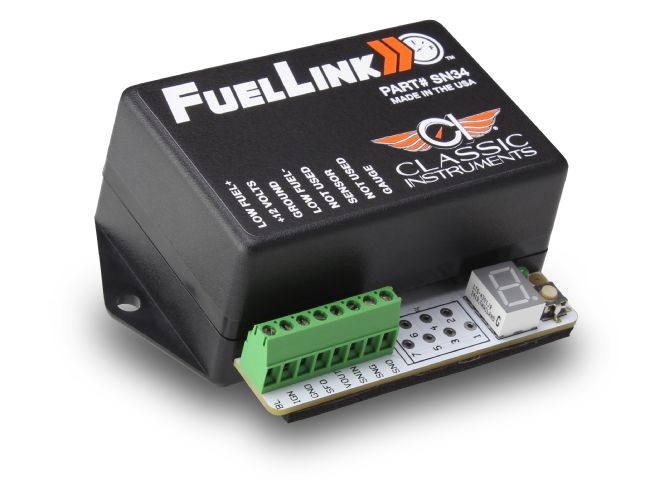
01 When a mismatched gas gauge and sender is the problem, Classic Instruments' Fuel Link is the solution.
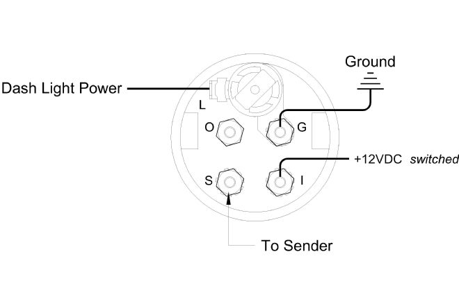
02 Typically a fuel gauge is simple to wire, the basics are a power source wire and another to the sender.
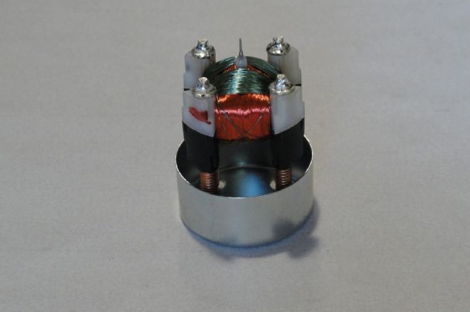
03-04 Fuel gauges may use a high-tech air core movement (top) or an old style thermal strip (bottom) to move the needle—in either case the changing resistance of the sender makes the needle move.

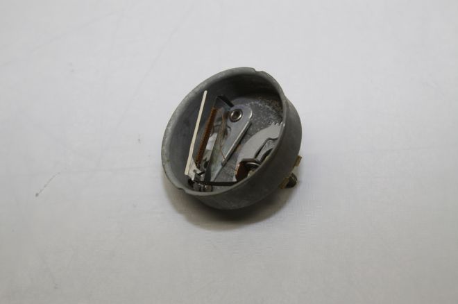
05 Gas tank senders have remained basically the same for years. This vintage unit is unique in that it has a cork float that turns a shaft to the variable resistor mounted outside the tank.
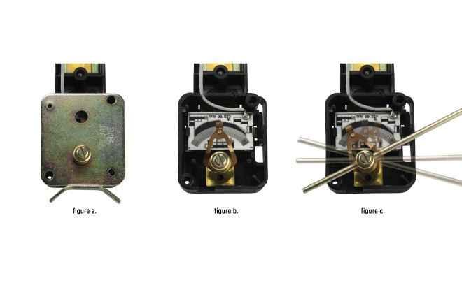
06 Contemporary senders have the resistor mounted inside the tank. Figure A is the assembly without the arm; B shows the sliding contact on that moves along the resistor; C is the lever connected to the float that causes the contact to move changing the electrical resistance.
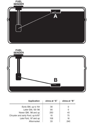
07 This chart shows the common values for senders and gauges at full and empty.
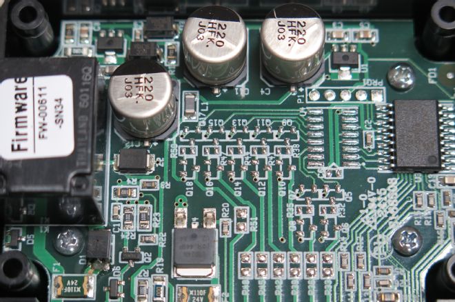
08 We're not even going to pretend we understand the operation of the Fuel Link's electronics, although Brennan claims it operates on 1.21 jigawatts.
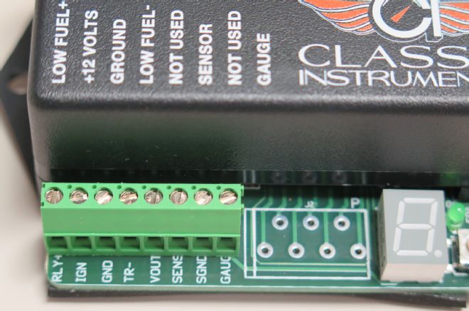
09 Connecting the Fuel Link couldn't be easier; all the necessary terminals are clearly labeled and have screw terminals for attaching the wires.