In our last installment on Scarlett, our ’72 coupe project car, we covered using relays and distribution blocks to lay the foundation for a solid, easy to service electrical system capable of powering whatever accessories we want to add. Now that we’ve almost completed the major wiring, we’ll actually miss this stage, with all that grip-strengthening crimping and hours of quiet introspection to ask questions like: “Why didn’t I hire this part out?” and “Should I have paid more attention in math class?” As usual, Scarlett is living at the Athens, Alabama-based Street Shop, Inc., where we’re doing the build.
This time we’re adding non-factory accessories, some of which are easier than others. Although we used multi-pin HES circular connectors from Delphi for the engine wiring, when we had other things that needed to go through the firewall we typically routed them through the original bulkhead, which is mounted to the back of the fuse block and has unused slots. Like most of the other connections inside the car, the bulkhead uses easy-to-find Packard 56 terminals that have a 0.250-inch blade and matching female socket that snap easily into place in the plastic bulkhead. Using it as our pass-through keeps everything looking nominally factory as well as eliminating the need to cut extra holes in the firewall.
One of the most important things we added was a pair of control boxes from ECPB, whose electric wiper and headlight door conversions we covered in depth in previous installments, and which proved a major part of making Scarlett more driveable (ever had to zip-tie your wiper door open? We used to, but not anymore). Since ECPB has released improved versions of both products, we updated Scarlett with the newer units. The newer headlight unit is an attractive, rectangular steel box that we hated to hide from view, but ultimately mounted out of sight on the rear of the driver-side inner fender. The wiper door unit, which is now round in place of their original square aluminum unit, bolts easily to the firewall in place of the failure-prone factory vacuum canister. With both units, we varied a bit from the standard instructions, which are written for those doing the installation without the luxury of having the car completely taken apart.
We laid aside the squeeze-on taps that are usually used to power the system in favor of wiring them directly. For example, since the headlight box draws its power by piggybacking onto one of the wires from the floor-mounted dimmer switch, instead of using a tap we cut the terminal off the factory wire that plugs into the dimmer switch. We then re-stripped it, twisted it together with the new wire and crimped them both into a single new Packard terminal. This was re-seated in the factory dimmer switch plug. The other end of the wire, which goes through the firewall to where the box is mounted under the hood, was terminated with another Packard terminal and plugged into the bulkhead. We handled things the same way on the underhood side.
Similarly, since the FAST computer we’re using is capable of handling Flex Fuel with the addition of a GM fuel analysis module, we installed the module in a bypass loop off the fuel line return and also used the bulkhead connector to wire it up to our ECU. In these days where you don’t know what you’re getting at the fuel pump, letting the engine adjust itself to whatever is actually in the tank seemed like cheap insurance. Like the headlight conversion, we chose the bulkhead as our location to get the wires through the firewall as cleanly and easily as possible. As with everything else we’ve done, keep detailed notes of what goes where.
Although we’ll probably add more electrical components in the future, this installment wraps up the wiring for now. By the time you read this, we’ll be on to larger, louder parts of the build.
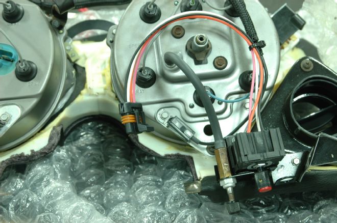
01. The Flex Fuel module, which we previously mounted to the rear of the driver-side inner fender, comes with a pigtailed Metri Pack connector. As with everything else, rather than butt splice those wires, we’ll remove them from the connector and create a new wire with a compatible Metri Pack terminal on one end and a Packard 56 terminal for the factory bulkhead connector on the other.
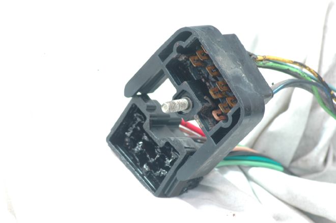
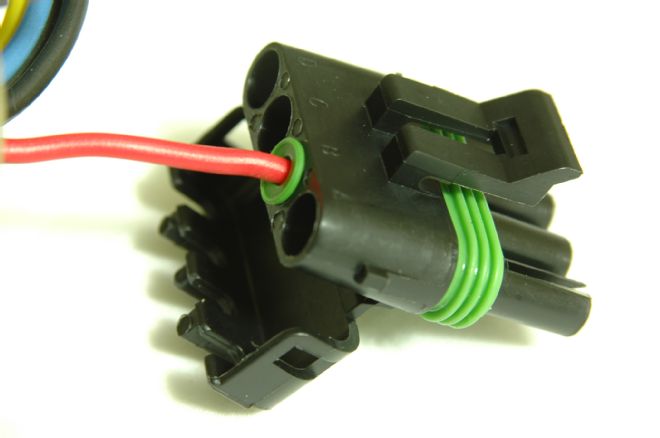
02. In order to keep the wiring as clean as possible, we used the factory bulkhead to route added-on wiring that had to go through the firewall. This is the underhood side of our original, now-replaced bulkhead. The other half is mounted to the back of the fuse block. Both use standard Packard 56 terminals that are readily available. The underhood side uses male terminals. The underdash side, female.
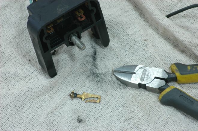
03. The female terminals in the underdash side can be easily removed with either a Metri Pack tool or a jeweler’s screwdriver. The male terminals are a bit harder to get out. Since the bulkhead is packed full of dielectric grease, which makes it much harder to work with, we just clipped the middle of the tab, pulled out the wire, and fished the loose end out of the grease.
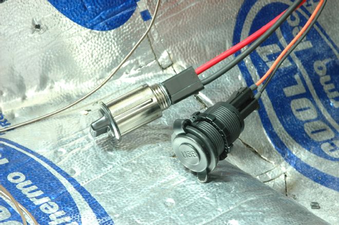
04. Since we all have more electronics than we did in 1972, we added a two-outlet USB charging port and an extra factory-style cigar lighter that can deliver a whopping 30 amps. Due to the high current capability, we powered it with a 10-gauge wire routed through our passenger-side circular connector. Both are fused and wired to constant-on power so you can charge your phone while the car is parked.
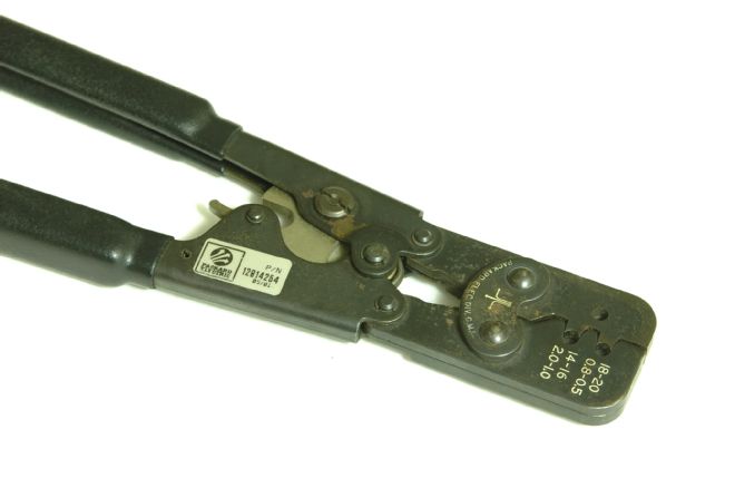
05. There are two sizes of Packard crimpers: one for Metri Pack and a larger pair for the similar Weatherpack terminals. They’re over $100 each, and worth every penny.
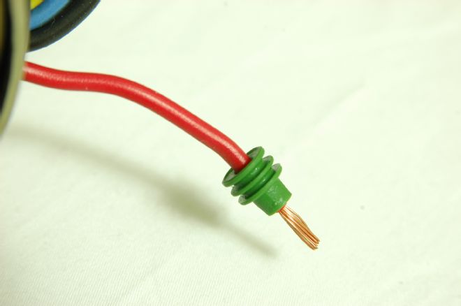
06. Both Metri Pack and Weatherpack connectors are assembled the same basic way. While you don’t have to slide on the rubber wire dress prior to stripping the wire, it’s a lot easier than waiting until you have all those loose copper strands to snag on things.
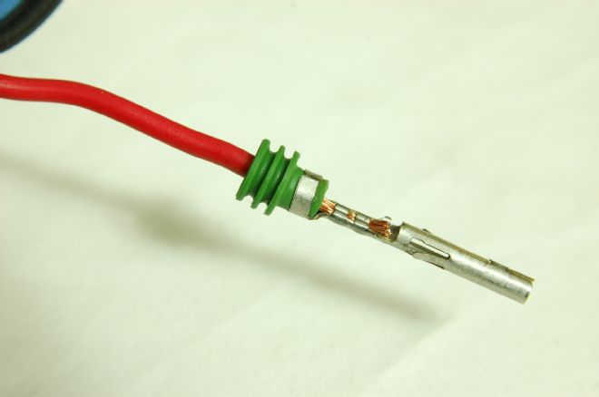
07. Once the wire has been stripped, slide the rubber wire dress forward, put the terminal on the end of the wire and align it in the crimpers, and squeeze. The Weatherpack tool crimps both the wire and wires dress parts of the terminal, and ratchet closed so they cannot be released until the terminal has been fully crimped.
08. Once the terminal is firmly crimped in place, seat it in the plastic connector and pivot the wire lock part of the connector into place. Metri Packs use a separate wire lock. While Weatherpack components typically use the words “shroud” and “tower,” they follow the common rule that a male terminal goes in a female connector and vice versa.
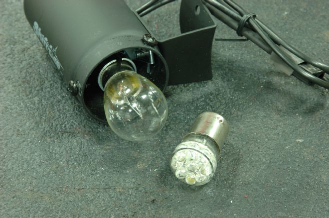
09. Because this is, after all, a race car, we added an Auto Meter shift light. Prior to installing it, we replaced the bulb with a much-brighter LED, which will also draw less current. The light will be activated by the FAST ECU, which has a switch-to-ground pin to turn the light on when the appropriate rpm is reached.
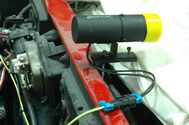
10. Since we intended for the shift light to be tucked up under the bulge of an L88 hood, we’ll fab a bracket to locate it correctly once the hood is in place. In the meantime, we mocked it up and re-terminated its two wires with a Metri Pack plug, and wired a matching plug with one wire from our fused power distribution block under the hood, and another that goes to the ECU.
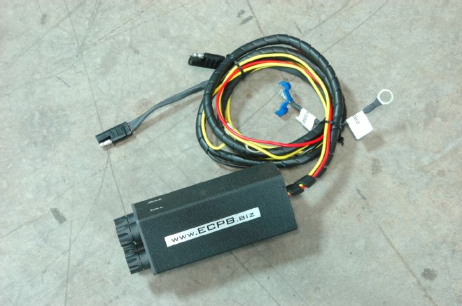
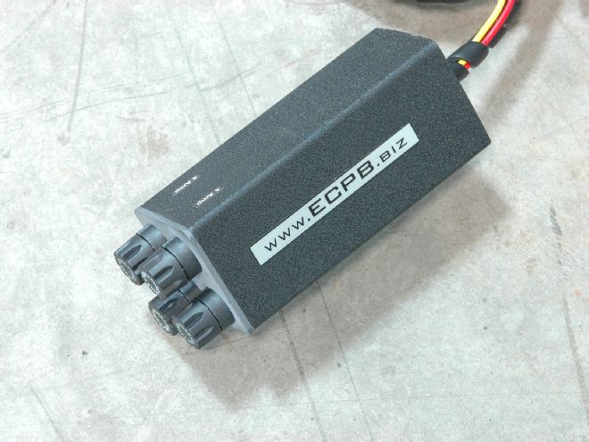
11. The control box for the ECPB electric headlight conversion. Although it’s a shame to hide something that’s done so well, we mounted it on the rear of the driver-side inner fender, close to the factory bulkhead that we used to wire it and the horn relay, which supplies its power. The wires that lead to the actuators (which are already installed) will be terminated with a single Weatherpack plug.
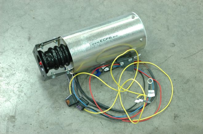
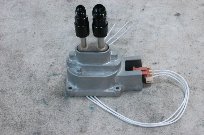
12. The ECPB electric wiper door conversion bolts into place where the vacuum canister used to sit on the firewall. For those who have suffered from the routine failures of the vacuum system, the ECPB unit is a godsend. While we wired the headlight unit directly to the bulkhead, we routed the wiper door wiring through a four-terminal Weatherpack connector.
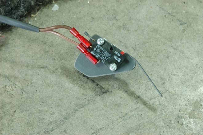
13. In addition to the power, ground, and trigger wires for the wiper door system, there’s also a microswitch that will need to be mounted beneath the grille just forward of the wiper door. Since we already had the original ECPB system installed, this will be as easy as unscrewing the old switch and screwing in the new one. If this is a new install, you’ll need to drill two holes in the grille support, preferably using a right angle drill.
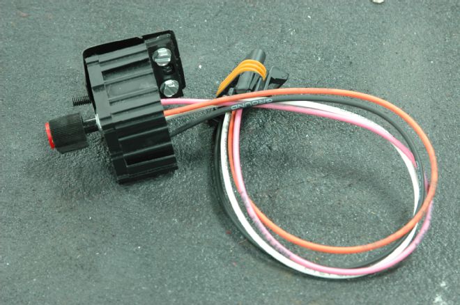
14. Not content with the courtesy lights just working, we decided we wanted them to fade out like a modern car rather than just cut off. This adjustable American Autowire unit does that and allows you to adjust the length of time before they go out. While the unit comes with a “pigtail” of wires, we’ve replaced that with a Metri Pack connector.

15. Our biggest problem was how to mount it, since the module came with a dovetail-mounted flat bracket that wouldn’t really fit anywhere we wanted to put it. So we had a bracket welded up to hold the dimmer unit.
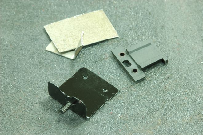
16. A piece of the sheet steel we started with, shown with the modified plastic bracket that slides into a dovetail on the module and the finished bracket. While the dovetail mount is interesting, it made mounting much more complicated. A simple tab with a hole would have saved an hour or more of fab time.
17. The module bolted into place underneath the dash near the odometer knob where it should be accessible but out of sight. We wanted to tuck it up out of the way, and this is about as far out of the way as you’re likely to get.
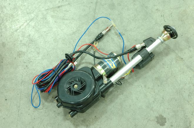
18. To keep the body of the car looking as clean as possible, we purchased this electric antenna conversion kit. It’s controlled by three wires: a ground, a constant-on source of power, and a trigger wire that usually gets power from the radio when it’s on.
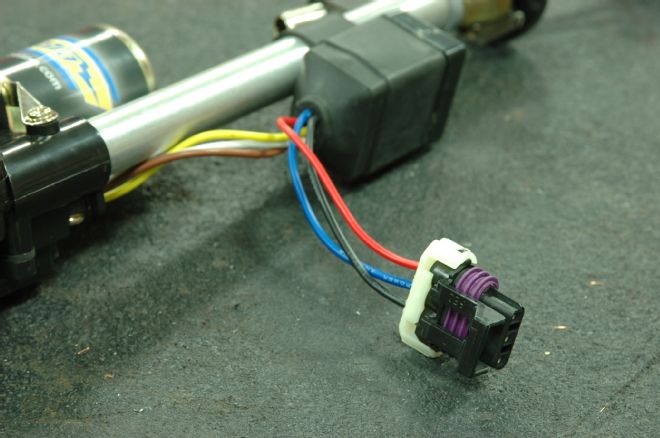
19. As is our way, the bullet-type connectors that came on the wires quickly wound up in our box of unused wiring components and we re-terminated that with a weather-sealed Metri Pack connector. The modern-but-vintage-style radio from Antique Automobile Radio that we’re using has a trigger wire that’s on whenever the radio is on: since we’ll often be using an iPod, we’ll install a toggle switch on that wire so the antenna isn’t up unless it needs to be.
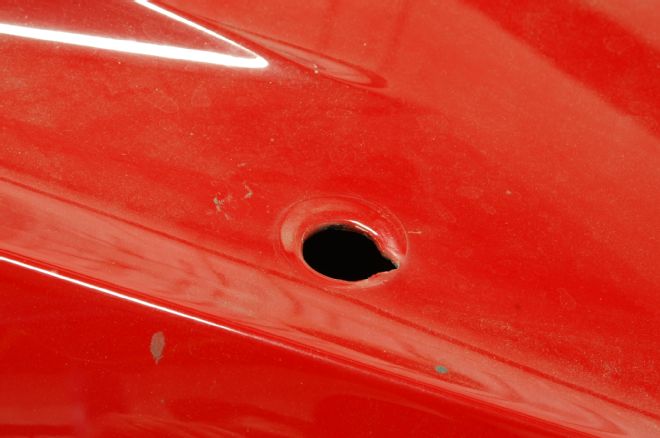
20. Prior to installing the new electric antenna, you obviously have to remove the old one, which is as simple as unscrewing the mast and unbolting the nut that holds the base in place under the rear deck. The antenna kit comes with a selection of bases, and you’ll want to make sure the one you pick covers the hole.
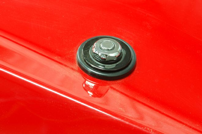
21. We chose the lowest-profile base that came with the antenna kit. The end result is much better than the standard screw-on mast, which, among other things, always has to be removed before putting on a car cover.