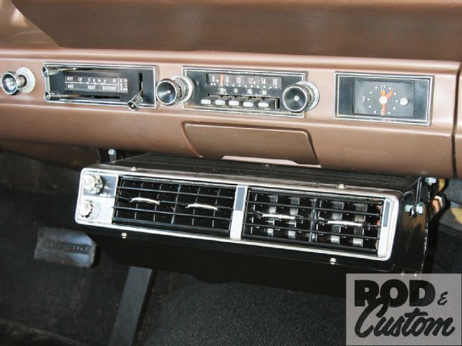
Wagons are hot right now. Unfortunately that's exactly what this Ford Galaxie wagon was—HOT! The 352 FE-powered Country Sedan was a non A/C-equipped car from the factory, and despite its cool lowered stance, rolling all four windows down to stay cool wasn't cutting it.
Kugel Komponents may be known for their independent front and rear suspensions and pedal assemblies, but they build cars too, and are a Vintage Air dealer, which is where we took the wagon, as they started the installation of a Vintage Air Mark IV underdash system.
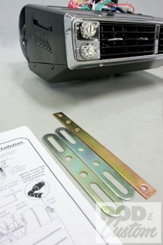
The Mark IV is perfect for vehicles that don't have room behind the dash for an evaporator, have a heater, and just need the addition of A/C, or when the owner wants the timeless look of chrome and a steel case. The Mark IV is an exact reproduction—using the original tooling—of the most popular underdash air conditioner ever made.
Not only is the unit compact (15 1/2 inches wide, 13 1/2 inches deep, 5 3/4 inches high), but installation is simple. Even the underhood installation was made simple with Vintage Air's dedicated FE engine compressor bracket. Once we received the correct one that is. (We, ahem, ordered the wrong brackets at first, but we never claimed to be perfect!)
It would have been simpler too if we'd had the correct pulleys. The Vintage Air compressor bracket is designed to use a two-groove water pump pulley (PN C8AE-8509-B) and three-groove crank pulley (PN D3TE-6312-AB). We had a two groove crank pulley and a single groove water pump pulley. We opted to keep our pulleys, align the compressor with the forward (unused) groove on the crank pulley, and incorporate an idler pulley, using an aftermarket Mustang idler from NAPA. Hey, even when a kit is a simple bolt-in, we like to do a little fabrication or it wouldn't be so much fun!
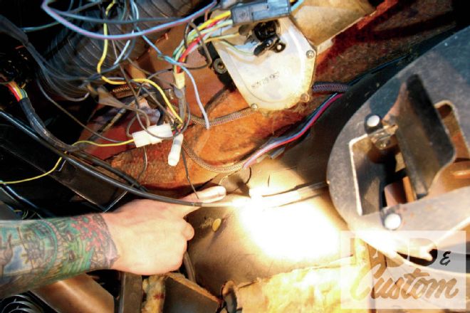
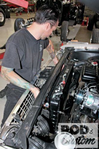
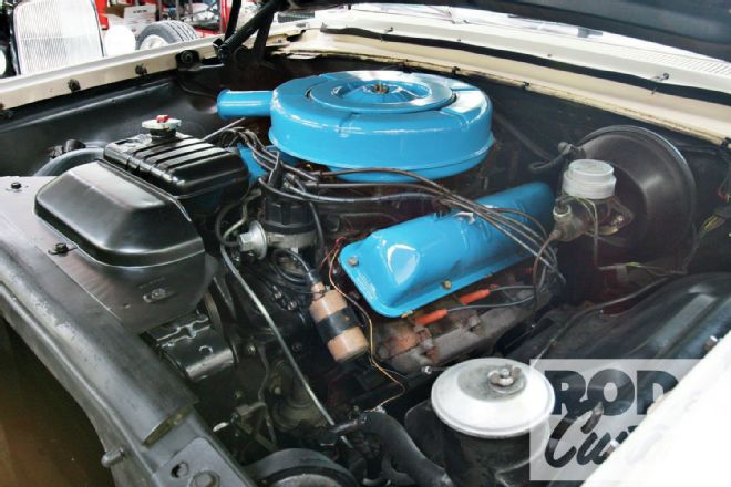 1. Here’s our subject, a 352 FE in a ’63 Ford Galaxie wagon. A cool car but not-so cool for the occupants with no A/C. We’re going to rectify that. First job: remove that coil, as the compressor will bolt to the front of the cylinder head.
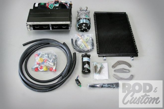 2. Here’s what we ordered from Vintage Air: A Mark IV underdash evaporator, with drain and fitting kit, compressor, condenser, dryer, trinary switch, and all hoses and ends. We ordered the wrong brackets initially (lower right).
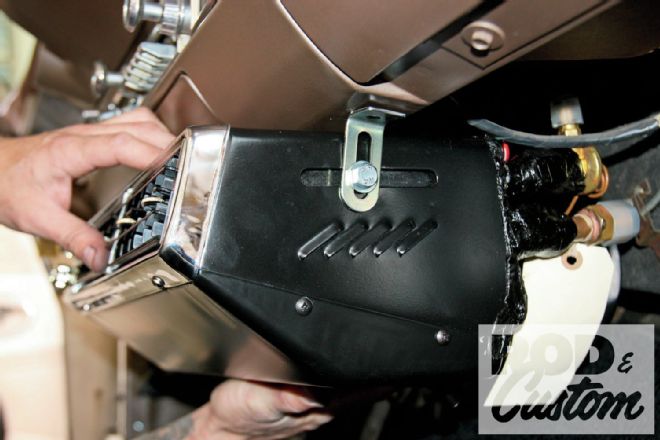
 3. Our first task was to mount the evaporator. These mounting straps are provided.
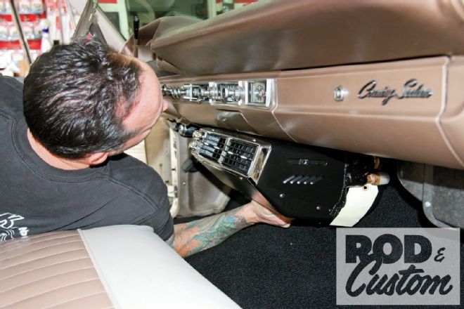 4. Chris Smith holds the evaporator in place to determine where it’ll best fit, taking into consideration clearance for the hoses on the rear and for the flaps on the heater housing.
 5. The evaporator has these captive nuts that can slide forward or backward (arrow). The dash also had a perfectly located hole for the mounting strap on the passenger side. The driver side had to be drilled.
 6. Smith used the bandsaw to cut a strap in half, and filed the ends before bending the two pieces in a brake.
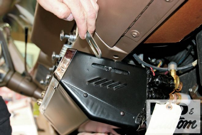
 7. The evaporator could now be mounted as shown.
 8. The longer strap provided was used at the rear, with a self-tapping screw locating it on the existing heater housing (arrow). This third mount will stop the evaporator from tilting.
 9. The two hose ends were installed to double-check clearance. We haven’t shown it but a drain hole was drilled in the floor and the drain tube from the evaporator routed through it.
 10. Smith points to a section of the sound deadener that can be easily removed for hose access …
 11 … which corresponds to this access hole in the firewall that is easily removed using a punch.
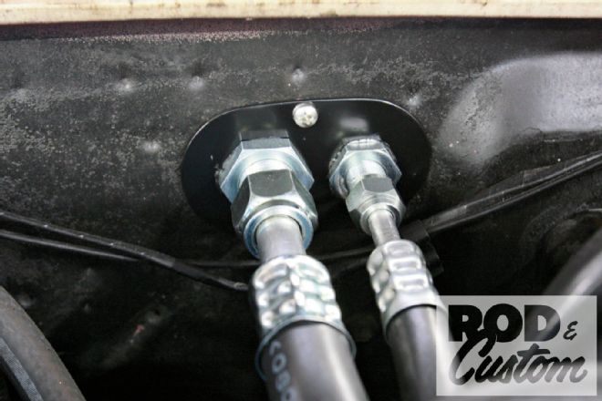
 12. From inside the assembled hoses are routed to the access hole above the driver’s feet.
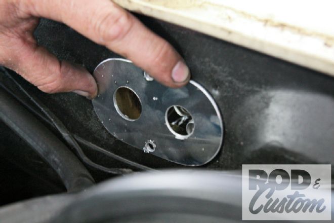
13. Smith fabricated this small panel through which the A/C hoses will pass.
12. From inside the assembled hoses are routed to the access hole above the driver’s feet.
13. Smith fabricated this small panel through which the A/C hoses will pass.
 14. The finished and painted panel, with the hoses installed.
 15. Once we’d realized our mistake and were waiting for the correct bracket to arrive, we “borrowed” a fabricated bracket (actually two separate brackets) from another 352 in the shop in order to mount the compressor and continue with the install.
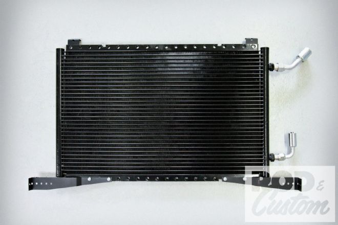
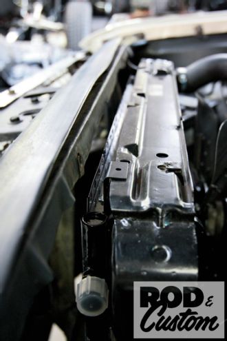
 16. Smith removed the upper fan guard/radiator mount in order to slide the condenser into place in front of the radiator and then determine how he’d mount it.
17. Using the brackets supplied, but cut down and bent at 90 degrees, the top mounts simply bolt to the radiator.
18. The lower mounts are also the brackets supplied, this time left at their original length but bent near the ends. Again, the hose ends were installed to ensure clearance.
16. Smith removed the upper fan guard/radiator mount in order to slide the condenser into place in front of the radiator and then determine how he’d mount it.
17. Using the brackets supplied, but cut down and bent at 90 degrees, the top mounts simply bolt to the radiator.
18. The lower mounts are also the brackets supplied, this time left at their original length but bent near the ends. Again, the hose ends were installed to ensure clearance.
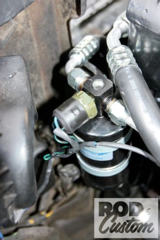
 19. The dryer was mounted on the core support, next to the radiator, well away from the exhausts. Note also the upper hose end installed on the condenser. Planning the hose routes prior to making the hoses will help eliminate mistakes.
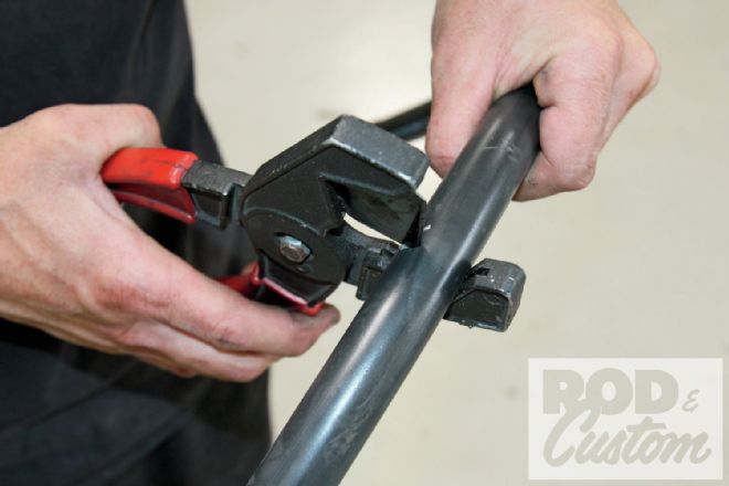 20. And speaking of making the hoses, a decent hose cutter will ensure all cuts are square and clean.
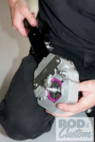 21. Not everyone will be able to warrant the expenditure for such a tool, and your local hydraulic supply house can probably make up hoses for you, but this Mastercool Hydra-Krimp hydraulic crimper does a perfect job, every time.
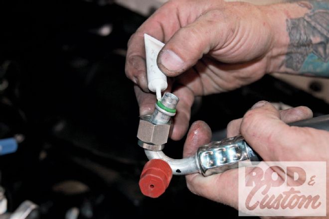
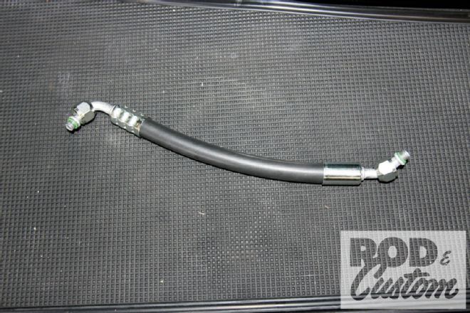 22. At the left is a crimped hose end, and at the right, before it’s crimped. Ensure you have the hose ends pointed in the right direction prior to crimping, as they do not swivel once crimped!
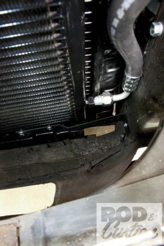 23. Here you can see the lower hose on the condenser, and the lower mount too, bolted to the core support.
 24. When assembling the hoses, it’s advisable to use the supplied oil on the O-rings, to prevent snagging and provide a proper seal. Vintage Air uses three different sizes of O-ring, depending on the hose application, and each has a specific torque setting.
 25. All the hoses are crimped and routed at this point, though not tightened as we still have to change that compressor bracket.
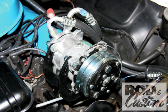
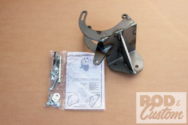 26. Here’s the correct bracket, a one-piece design that mounts the compressor, offers adjustment, and bolts directly to the cylinder head.
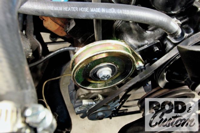
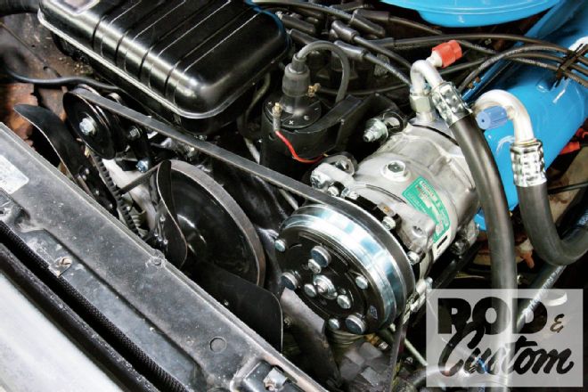
27. With the bracket painted, the compressor was installed and aligned with the front groove on the crank pulley. We now had a decision to make: purchase the correct water pump and crank pulleys to align everything, or add an idler pulley and retain the existing belt on the water pump, crank, and previously fitted alternator.
28. This idler pulley is available from NAPA stores and suited our requirements perfectly. Once a sufficient spacer was machined (arrow) to align the pulleys, it was bolted to existing bracketry …
26. Here’s the correct bracket, a one-piece design that mounts the compressor, offers adjustment, and bolts directly to the cylinder head.
27. With the bracket painted, the compressor was installed and aligned with the front groove on the crank pulley. We now had a decision to make: purchase the correct water pump and crank pulleys to align everything, or add an idler pulley and retain the existing belt on the water pump, crank, and previously fitted alternator.
28. This idler pulley is available from NAPA stores and suited our requirements perfectly. Once a sufficient spacer was machined (arrow) to align the pulleys, it was bolted to existing bracketry …
 29. … and an adjuster arm fabricated from two Heim joints and a length of threaded aluminum tubing.
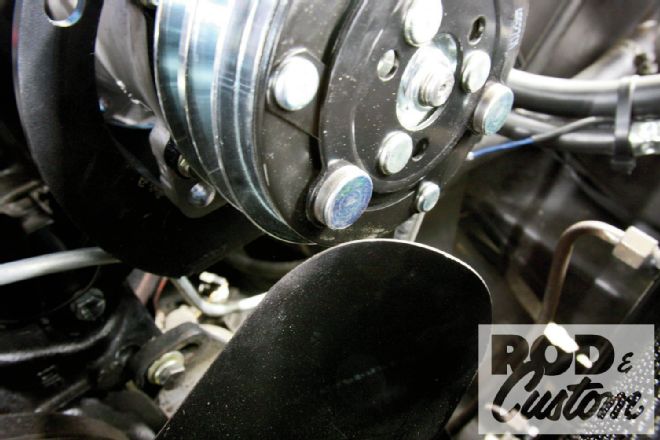 30. While the fan did clear the compressor, clearance was minimal, so a 1/2-inch spacer was added between the fan and the pulley.
31. With the idler pulley adjusted so the belt would pass under the expansion tank, the correct length belt was determined and purchased.
30. While the fan did clear the compressor, clearance was minimal, so a 1/2-inch spacer was added between the fan and the pulley.
31. With the idler pulley adjusted so the belt would pass under the expansion tank, the correct length belt was determined and purchased.
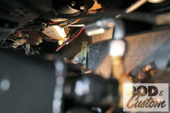
 32. A trinary or binary safety switch must be included in the system. It disengages the compressor clutch in cases of extremely low or excessively high pressure, to prevent compressor damage or hose rupture. While our system only needed a binary switch, we used a trinary, which combined the high/low pressure protection with an electric fan operation signal, allowing for future addition of an electric fan.
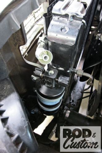
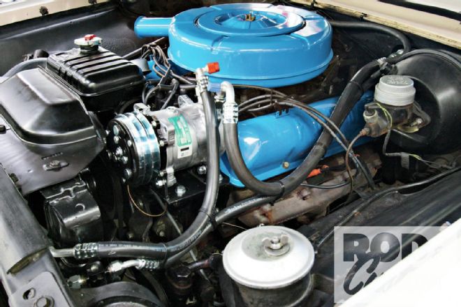
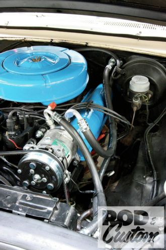 33. The completed installation.
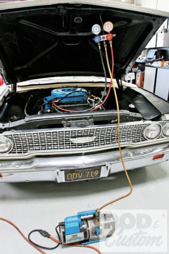 34. With all fittings tightened, the system was evacuated (all air removed to create a vacuum) for 35-45 minutes. This should be done with all components at a temperature of at least 85 degrees. Once leak checked, the system was charged with 1 pound and 12 ounces of R134a refrigerant (not shown).