Last month we discussed the basics of your car's 12-volt electrical system with the goal of understanding enough to trace problems to a particular electrical component. This month we're going to delve into the diagnosis and repair (or replacement) of some switches and relays.
Typical "completes-a-ground" switches include doorjamb switches that operate interior lights, the horn switch in the steering wheel, and Neutral safety switches. A regular switch completes the circuit between the power source and the accessory, allowing the electricity to flow to the accessory, through it and to the ground. With a completes-a-ground switch, power flows through the accessory/relay, into the switch, and then to the ground.
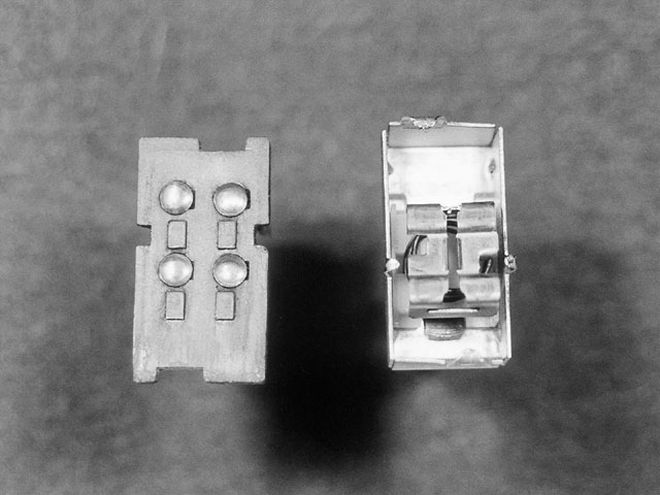 This shows the simple insides of the emergency flasher switch. The underside of the "lid" is on the left, the mechanical part of the switch is in the half on the right. When assembled, the bumps (contacts) are inside the box across from the metal bar. The sliding bar in the box moves when the switch's lever is moved, touching the bar to the copper contacts in the base. One of those bumps on the lid was dirty, and that was the switch's only problem. It was cleaned with 600-grit sandpaper and now works like new.
Relays are small boxes that contain an electromagnet which, when activated by current flowing through it, pulls down a bar that completes the circuit and allows the current to flow to the accessory. Relays are often controlled by completes-the-ground switches. When a relay that's getting power no longer works, the problem is frequently corroded points or a broken wire.
Some switches and relays should just be replaced when they quit working. If the headlight switch on your car is bad and only costs $13, replace it. However, not all switches and relays are cheap or easy to come by, and if you have the correct original part, you may not want to replace it.
Repairing Switches
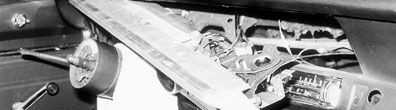
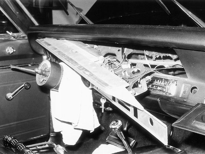
To illustrate the repair of some switches, we'll use the emergency-flasher switch and a headlight switch on a '69 Barracuda. The right front turn signal wouldn't light up when the emergency-flasher switch was turned on; however, the light did work as a right-turn signal or parking light. The problem was traced to a bad emergency-flasher switch, which we tried to repair before replacing it.
The flasher switch has four small metal tabs that hold the top casing to the bottom part. The tabs are pried up and the switch is carefully pulled apart. Be careful when pulling switches apart, because many of them (this flasher switch included) have springs that force the contacts tightly together. If you're not careful, the springs will go flying. The flasher switch is a simple sliding bar with copper contacts that touch other contacts when the switch lever is moved, completing the circuit. The corroded contact is easily visible and quickly cleaned with 600-grit sandpaper. Then the contacts are greased with a little di-electric grease, the switch reassembled, and the tabs bent back down. It works great, and some money is saved.
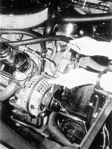
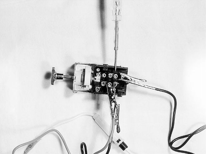 This shows proper testing of a headlight switch. The fused jumper wire is used to connect the switch's running light terminal to the battery, and the non-fused black jump wire jumps from that terminal to the headlight Power In terminal. Use the circuit tester to test switch terminals based on the knob's position.
Some switches, like the headlight and windshield wiper, are held together with rivets instead of bend-over tabs.
If the switch is the problem, you can replace it or attempt to repair it. To get riveted switches apart, drill out the rivet heads and separate the switches very slowly-these are more complicated and may have several loose parts inside them. However, they operate on basically the same concept as the emergency-flasher switch. Clean everything with some 600-grit sandpaper, apply a little di-electric grease to the contacts, and reassemble the switch, using screws or thin bolts in place of the rivets if you can't find replacement rivets locally. (Try industrial supply companies for the rivets and setting dies.) If the switch still doesn't work, you're no worse off than you were before, but there's a chance it will. And it may just be the little kid in us, but it's fun to see what makes them tick!
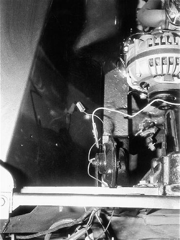 This shows the direct jumping of the horn to the battery's positive terminal. Use the fused jumper wire and touch the horn's Power-In terminal briefly. A good horn will honk and point to a problem elsewhere.
Relay and Horn Circuit Repair
Our '69 Barracuda is an example of how to trace the cause of a malfunctioning relay circuit. Using the seven-step diagnosis check list, first check the fuse, then move on to the horns themselves. If the fuse is good, disconnect the wires from the horns, attach one end of the fused jumper wire to the positive battery cable, and briefly touch the other end to the wire terminal on the horn. If the horn doesn't sound, it's probably bad. If it does sound, it probably isn't getting power. To test for power, ground the circuit tester and touch the inside of the horn wire connector with the probe. When your assistant pushes the horn button, that wire should be hot. If the wire is hot and the horn didn't work in the previous test, make sure the horn is properly grounded and all connections are clean. If you've checked the grounds and the horn itself doesn't work even though it's getting power, you'll need to replace the horn.
If, however, the horn did work when directly jumped but there's no power at the horn wire, we need to look further upstream for the problem. We'll test the horn relay next.
On the Barracuda, the horn relay is on the left kick panel, close to the driver's left knee. The location varies by vehicle, so find it by consulting your factory shop manual. If you have trouble finding it (or any other relay, switch, or component), look at the wiring diagram to see how many and what color wires attach to it. The Baracuda's horn relay has three wires; a black 18-gauge wire, a purple 16-gauge wire, and a dark green 16-gauge wire with a red stripe. When we found the relay with that wire combination, we knew it was the horn relay.
 With a well-grounded circuit tester, the horn wire should be hot when the horn button is pushed. If it's not, check the horn relay next. If it's hot, the horn is either not grounded or it's bad.
The three wire terminals are appropriately labeled on the relay; Power In from the battery "B," Power Out to the horns "H," and Power Out to the horn switch "S." When the horn button is pushed, the horn switch completes the ground and allows power to flow from "B" through the electromagnet, out through "S," into the horn switch, and into the ground. This complete circuit activates the magnet and pulls down the bar. This allows power to flow from "B" through the contact points to "H" and to the horns. The single Power In wire provides power to both the horn switch and the horns. To test the relay, ground the circuit tester and touch the probe end to the Power In wire in the connector. You can touch it from the back where the wire goes into the connector. It should always be hot. If it is hot, unplug the "S" wire and connect one end of the fused jump wire to that terminal on the relay. Briefly touch the other end of the wire to a ground. This accomplishes the same thing as a good horn switch completing a circuit, and a good relay will make the "H" terminal hot and honk the horns. If terminal "H" wasn't hot and the horns didn't honk, the relay is bad-buy a new one or try to repair it the same way you would repair a switch in the previous examples.
If terminal "H" tests hot but the previously-tested good horns didn't honk, that means the relay is OK, but there's a break in continuity somewhere between the relay and the horns. Drag out the wiring diagram and start tracing wires for problems. While you're under the dash, there's one last test to make absolutely sure that the circuit between the relay and the horns is good. Disconnect the connector that covers the "B" and "H" terminals and, with the fused jumper wire, directly jump these two wires together at the connector. If the circuit is good, the horns will honk.
If the horns work when you ground-out the relay but don't work when pressing the horn button, it's time to pull the steering wheel (you'll need a steering-wheel puller).
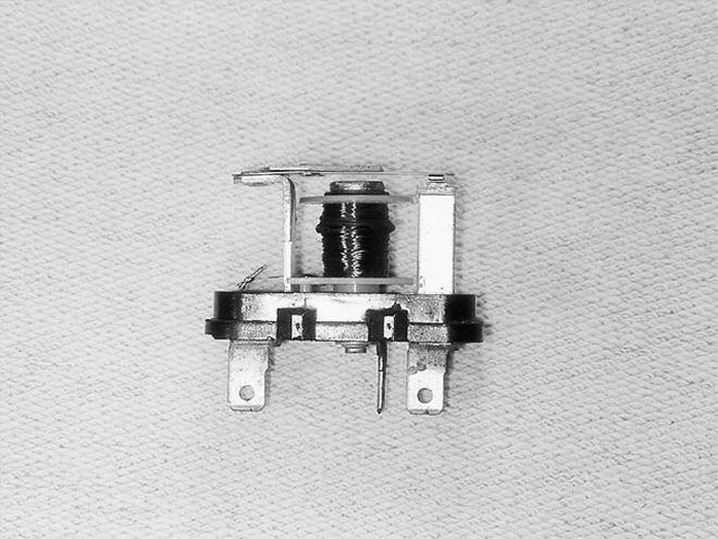 This is the horn relay. Terminal "B" is Power In, "H" is Power Out to the horns, and "S" is Power Out to the horn switch (ground). When the electromagnet (the wire-coiled spool in the middle) is activated, it pulls down on the bar and closes the points. That completes a circuit and sends power to the horns.
With the steering wheel off, we'll look for either dirty contacts or a broken wire and test the horn switch. The horn switch has a roller on the end of it that makes continuous contact with a copper disk on the back of the steering wheel. The disk which has a wire that connects to one of two closely spaced metal plates in the horn button. When the horn button is pressed, it forces the two metal plates together and completes the circuit through the horn switch. Your horn button may be different, but the theory will be the same.
Test the horn switch by touching the roller with the other end of a properly grounded jump wire. If touching the top of the roller on the horn switch doesn't honk the horn (remember that the horns, relay, and circuit to the horns already tested good), and touching the bottom of it (where the wire connects to it) does make them honk, you have a bad horn switch. Look for the break in the horn switch-a broken part or a broken wire, and decide if you can repair it or need to replace it. In this instance, we're able to repair and reuse the 'Cuda's horn, as it only has dirty contact points that were easily cleaned with 600-grit sandpaper. Take some 600-grit sandpaper to the copper disk on the back of the steering wheel and clean everything while you're in there.
Although lots of possible switch/accessory/relay combinations weren't covered, enough was covered to allow the average do-it-yourselfer to understand how everything works, diagnose nearly any problem, and determine a course of action for repair or replacement. There really is no reason to pay an automobile electrician $60 an hour to do the same diagnostic steps covered here.
Next month we'll look at how to diagnose and repair problems with your car's gauges.
Tip O' The Day
Hate working under the dash as much as we do? Make your life easy and spend 15 minutes removing the front seat (or seats). You'll more than make up that time by not contorting your body into a back-breaking position to work under the dash. With the front seats out, you can lay on the floor of the car and work under the dash comfortably.
Seven Steps to Diagnosing an electrical problem