Are your old musclecar's headlights too dim? Want to add a new high-current accessory without overtaxing the existing electrical system? Perhaps you need to activate an electric fan or nitrous system by means of an automatic switch. You could accomplish these tasks by rewiring the entire circuit using heavy-gauge wire, but that's time-consuming, adds needless weight, and is electrically inefficient. A far better solution is to use a relay.
A relay is a type of heavy-duty remote-control switch able to handle high-current accessories, yet capable of being actuated by substantially less current. Relays are installed between the power source and the electrical accessory requiring on/off power. When the relay is energized (turned on), the high current required to operate the accessory flows from the power source, through the relay, and directly to the part.
Supplying high-current devices requires heavy-gauge wire; the longer the circuit the larger the required conductor diameter. In 12-volt automotive electrical circuits, even small amounts of resistance can cause significant amounts of voltage drop. Circuits with long wire length and multiple switches and connections inevitably have a certain amount of voltage drop caused by normal resistance buildup; deterioration from vibration, high temperatures, and corrosion only compound the problem. Relays provide a solution by shortening the required length of the heavy-gauge power delivery wire from the battery or alternator to the load.
Relays are typically energized through an operator-controlled dash-mounted switch, or by remotely mounted pressure-, vacuum-, or linkage-actuated switches. With only a small amount of current needed for the relay-actuation side of the circuit, you can use a low-amp on/off switch and small-gauge wire (even on long runs) to connect the on/off switch to the power source and relay. The diagrams on these pages show just some of many typical relay uses, as well as how to hook up the universal ISO relay sold by M.A.D. Enterprises, Jacobs Electronics, and other electrical suppliers.
Using a relay as a heavy-duty remote-control device ensures delivery of full power to high-load electrical components: Your headlights will burn brighter, your electric fan will run faster, and fuel pumps will operate at their peak efficiency. Voltage drop at the dash harness is reduced, and overall switch and electrical system performance and longevity are enhanced.
How It Works
This diagram illustrates the function and operation of the versatile ISO-style "1 Form C single pole/double throw" (SPDT) relay. It can be used to control both normally open (NO) and normally closed (NC) circuits, or it can act as a change-over device to switch current from one user to another. The low-current switch controlling the circuit sends current through the pull-in winding terminals (85 and 86). This energizes an electromagnet that pulls a movable arm, closing the NO high-load circuit (30 to 87). When the controlling switch stops current from passing through the magnetic winding, spring action pulls the movable arm in the opposite direction, completing the NC high-load circuit (30 to 87a).
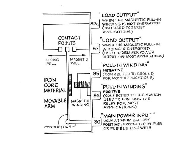
The ISO relay's high-load circuits are rated at 40 amps NO/20 amps NC for resistive loads, and 20 amps NO/15 amps NC for inductive or lamp circuits. Other ISO relay variations may have only NO or NC circuits, but because of the terminals' universal numbering scheme, you can always figure out their function and how to wire them.
Cooling Fan
M.A.D. likes to use two relays to power up one large electric cooling fan. Even though the ISO relays are rated at 20 amps for this application, experience has shown a large fan motor will overheat a single relay. Installing two relays in parallel removes stress loads from each relay and improves reliability with redundant parts. (One relay per fan is sufficient for systems with two small fans.). Fans' relays are typically actuated via an engine- or radiator-mounted thermostatically controlled switch, but you may wish to install an extra manually operated switch on the dash as a fail-safe device.
Headlights
Mounting relays near the front of the car makes it easy to route high-amp current directly to the headlights. The factory headlight switch and beam-select switch need only energize the relay for it to send full battery power into the front lighting system harness. This removes the load from the dash harness and is recommended for old under-wired musclecars or any vehicle upgrading to high-power halogen lights.
Fuel Pump
This circuit delivers maximum current to the fuel pump and enhances safety by using a factory GM oil pressure switch. With the ignition in "run," engine oil pressure closes the switch to complete the circuit from terminal "I" to terminal "P," which delivers power to relay terminal 86 and to the ground via terminal 85. This energizes the relay, allowing battery positive power to flow directly through terminals 30 and 87 to the fuel pump. When the engine stops running, oil pressure drops, the switch opens, and the relay de-energizes. This provides automatic fuel pump shutdown after a crash or engine failure, and also prevents the fuel pump from running if the ignition is left on. Wire the pressure switch's "S" terminal to the ignition "start" circuit to provide fuel pump pressure during engine cranking, and/or prime empty carb float bowls.
Mount the relay as close to the battery as practical, and install a fusible link two wire-gauge sizes smaller than the high-amp power feed fire. Wire the pressure switch using generic 1/4-inch female-blade terminals or a three-prong, weather-resistant, molded-on, 56-series connector assembly: GM 12101928 (AC-Delco PT200) has a black PVC connector-shell; slightly more expensive GM 12085529 (AC-Delco PT139) has a high-temp TPE shell.
Voltmeter
Many cars experience voltage drop in the main-feed wire that delivers power to the dash area. The more dash switches that are turned on, the greater the power drop. This can cause the voltmeter at the dash to display a significantly lower voltage than the actual battery voltage. You may think there's a problem with alternator output, when in fact the alternator is working fine. The voltmeter can be made to show exact battery voltage by wiring up a relay as shown here. Be sure to route the wire from relay terminal 30 directly to battery positive, and that no other circuits use this wire.