A well-designed hot rod incorporates a great amount of creative elements into its build to make it stand out from the rest. From the most elaborate suspension setup to the simplest hinge, custom fabrication is something that takes both vision and talent to bring it to life.

There are specific dynamics that come into consideration when the time comes to installing an engine and transmission into a new chassis. This is especially true when needing to settle a vintage combination between the 'rails, as many chassis manufacturers don't offer simple bolt-in mounts for your specific application. Related installation issues include where the engine will sit in relation to the firewall and radiator, how plumbing will be affected, and attaining the perfect plane for the driveshaft once everything is bolted in.
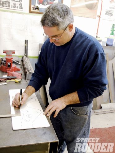 After taking plenty of measurements with the engine and transmission mocked up in the chassis, Keith Cornell of Rolling Bones Hot Rod Shop used some basic drafting tools to design the engine-mounting plate template on a piece of Masonite board.
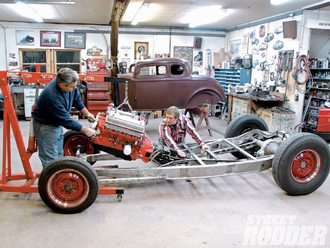
The Rolling Bones Hot Rods Shop in Greenfield Center, New York, has dialed in more vintage engine combinations than we can count, so it was a perfect opportunity to follow along as they nailed a vintage 312ci Ford V-8 coupled to a T5 transmission into one of their newly completed chassis.
Instead of using the factory engine mounts located on the side of the engine block, Keith Cornell of Rolling Bones prefers to construct his own engine mounting plates, which are secured to the front of the block. This style mount not only gives the finished car a vintage race car look, it also acts as a perfect anchor to the chassis. To get started, Cornell fabricated a pair of temporary engine mounts fashioned from rectangular steel and bolted them into the factory mount locations. With the engine secured to the transmission they lowered the combination into the chassis and mocked it into place.
To assist in the correct placement within the chassis, the Deuce firewall was bolted in and the radiator was also secured to where it would be positioned. Once the fore and aft proximities were dialed in, Cornell adjusted the pitch of the engine and transmission, marked each spot for placement, and began to design the engine-mounting plate. With the radiator now removed, he began taking measurements and transferring them onto a sheet of durable Masonite. Taking into consideration engine pulleys, accessory mounting points, and water pump access, he used simple drafting tools, including square and curve templates to approximate the design. Once completed, he used a razor knife and hole punches to carefully cut out the template while intentionally leaving the ears of the mounting plate long for trimming once installed to the front of the engine block.
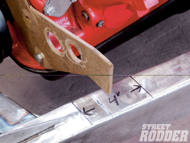 When the chassis was built, special provisions were made to incorporate a 4-inch-long section of 1/2-inch plate steel along the upper inside portion of the framerail. This will allow Cornell the opportunity to locate the engine-mounting plate in just the right spot.
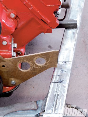
With the template mounted in place, Cornell measured for proper placement to the chassis, in this case 1 inch in from the outer 'rail on each side, which he marked with a black marker. Using a square, Cornell marked the area to be trimmed and removed the template from the engine to conduct the final cut. The completed template was then sent to CBM Fabrication in Ballston Lake, New York, to have a water-jet version cut from 3/8-inch steel plate.
 The completed engine-mounting plate was now ready to be created from 3/8-inch steel plate.
To help dampen vibration when bridging the engine-mounting plate to the chassis, a call was placed to Speedway Motors for one of their Universal Bolt-Through Engine Mount Cushion kits (PN 7209314) to utilize a number of parts within the kit in the adaptation. Included in the kit is a pair of 3-inch rubber biscuits and base cups, which needed to be modified to fit the application. Since Cornell wanted a nice clean look to the outer framerail where the biscuit would normally overhang, he removed an outer section of the rubber mount using a belt sander and followed by adapting the mounting cup base to reflect the same new angle by trimming the outer diameter and welding a small lip to the edge using mild steel.
Once the engine-mounting plate was back from CBM Fabrication, it was bolted into place so Cornell could follow with measurements for support mounts to the inner framerail. Wanting the mounts to be as stout as possible, a section of 3-inch pipe with 1/8-inch wall was selected for durability. Measuring from the top of the inner framerail to just below the base, a half-moon section was marked and cut in a bench vise using an air driven cutoff wheel while wearing eye protection. The section was then massaged using a grinder and belt sander to fit the outer circumference of the rubber biscuit and base cup from where it overhangs the inner framerail. Cornell then followed by making a small filler piece from 1/8-inch plate steel for the top of the mount for added strength, which he TIG-welded into place and grinded smooth.
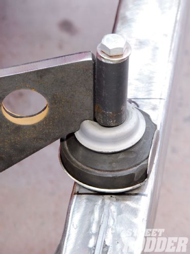 Starting with the modified Speedway Motors cushioning biscuit and base cup, the notched Guide headlight base cup was lowered into position. Cornell cut a section of 7/8-inch diameter with 1/8-inch wall steel tubing next to mount to the notched base cup and engine-mounting plate. He then dropped a bolt and washer into place to illustrate the final mock up of the unit.
Prior to welding the support into place, it was time to address the link that would tie the engine-mounting plate to the chassis. It's a well-known fact that the Rolling Bones team recycles as many vintage parts whenever possible into their builds. To top the 3-inch rubber biscuits, a set of vintage Guide headlight base cups were notched to fit the side of the engine-mounting plate. For the upper tie-in, Cornell used 7/8-inch steel pipe with a 1/8-inch wall to bring everything together. When the perfect alignment was attained, Cornell secured the parts with a vise, removed the engine-mounting plate, and TIG-welded everything together. After reinstalling the engine-mounting plate, Cornell used a center punch and hammer to set the exact spot needing to be drilled and tapped atop the framerail. An accommodation was made for the engine mount by installing a 1/2-inch steel plate bung under the upper framerail. Cornell removed the engine-mounting plate and drilled the mounting hole with a 25/64-inch bit. He tapped the hole with a 7/16-inch fine tap and once the area was blown clean, reinstalled the mounting plate, securing it to the block and chassis with Grade-8 bolts and washers. The final TIG welding was then completed to the supports for the inner framerails.
With the engine finally secured into place, Cornell focused on fabricating a mounting plate for the T5 transmission. Using a piece of Masonite board, Cornell measured and designed a simple yet functional transmission mounting plate, which was cut out from 1/4-inch plate steel; 1/4-inch shims were also incorporated to allow the plate to drop down from the frame to accommodate proper clearance for the tailshaft of the transmission. Once the plate was deburred and secured into place, Cornell used angle finders on the ends of both the transmission tailshaft and rearend yoke to ensure they were both at 0 degrees before measuring for the driveshaft. After determining the length of 37 inches, a call was placed to Universal Driveshaft in Albany, New York, for one of their all-steel units.
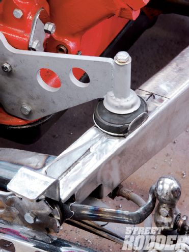 Once completed, the engine-mounting plate was secured into place along with the base cup, cushioning biscuit, notched upper cup, and 7/16-inch Grade-8 bolt and washer.
Well, there you have it: A simple and easy guide to installing a vintage V-8, a modern manual overdrive transmission, and a driveshaft that will yield you a powertrain that will be sure to give you countless miles of driveability. The completed installation is not only one with killer looks, but one which should be durable enough for the toughest abuse of both local and cross country runs, which the Rolling Bones team proves every time they tank up and hit the road hard.