Twin Disc Clutch
The twin disc clutch is now gaining popularity mainly due to the stupid amount of 21st century power car crafters are making. This puts the arm on transmissions, torque converters, and especially clutches to transfer all that power without failure. The answer to a stronger clutch is not necessarily a stiffer pressure plate. The torque capacity of any clutch is based on three basic parameters: clamp load, surface area, and coefficient of friction. Increasing any of these factors (like surface area) allows the designer to change the other two variables. As an example, by doubling the clutch surface area with the same coefficient of friction, a single-disc clutch that can hold 500 lb-ft can now reliably hold 1,000 lb-ft. Centerforce has come up with an innovative variation to the two-disc street clutch that is so new it still doesn't have a name. The most interesting part of the clutch is the hub-pin drive that connects the primary and secondary discs. One issue with dual-disc clutches is there is limited room on the transmission input shaft for two splined hubs. By pinning the two clutches together, the second clutch disc does not need hub springs, reducing the weight of the second disc. As you can see, the company put some serious engineering into this design.
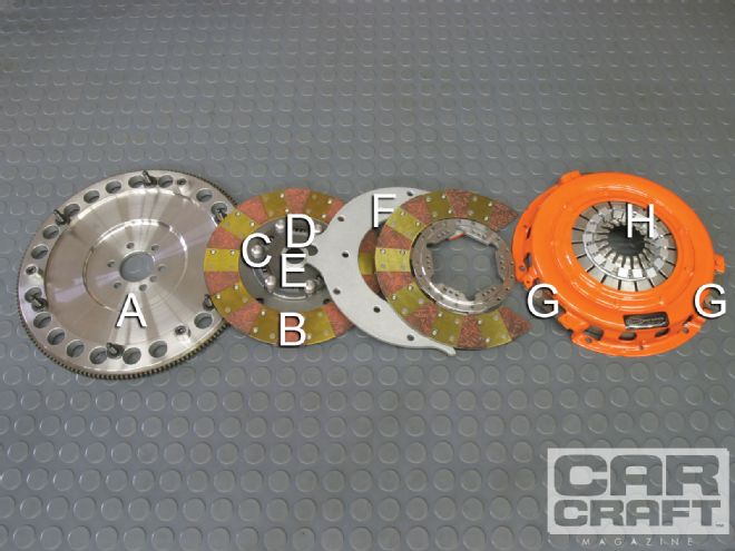
A. The flywheel generally supplies the most weight in the twin disc clutch system. Heavier flywheels store more energy than lighter flywheels at the same rpm (assuming the same diameter), which becomes evident when attempting to accelerate a heavy car from a stopped position. The energy stored in the flywheel is subject to something called rotational inertia that increases when additional mass is located farther away from the centerline of rotation. So a larger flywheel with more weight concentrated on the outer ring of the flywheel will require more power to accelerate. Given this, Centerforce reduces the weight located at the outer edge of the flywheel to improve acceleration. Removing the same amount of weight closer to the center of the flywheel would not improve acceleration as much as removing the weight farther away from the centerline.
B. Dual-friction discs are also part of this twin disc clutch with a high-temperature organic (nonasbestos) material on one side of the clutch face and Centerforce's metallic-ceramic alloy on the other. This combination of friction materials allows the clutch designer to increase the holding power while still delivering a friction surface that is not too aggressive.
C. The Centerforce clutch reduces weight in the second disc by using the drive lugs to directly connect the primary clutch disc with the nonsprung secondary disc. The secondary disc relies on the springs in the primary disc to eliminate chatter.
D. All street clutch discs require a spring-loaded hub that tends to absorb the clutch material's initial hit during engagement. The springs damp the initial oscillations of the clutch disc, minimizing potential clutch chatter.
E. The clutch hub is designed with a softer steel alloy than what is used in the input shaft of the transmission so it will wear before the transmission shaft. One key to a quality clutch is how well the splines on the clutch hub fit over the transmission input shaft. Sloppy spline teeth from an inexpensive clutch can cause all kinds of clutch engagement issues and contribute to input shaft wear.
F. Virtually all street clutches also employ what is called a Marcel spring between the two facings of the clutch friction material. This is a very thin, wavy spring that also helps to damp the chatter of the engaging clutch. Race clutches do not employ a Marcel spring and can be very harsh on the street as a result.
All dual-disc clutches must employ a midplate or floater secondary flywheel surface that is attached directly to the flywheel. It provides a flywheel surface connected directly to the crankshaft for the secondary clutch disc. This surface must float when clutch pressure is released (clutch pedal depressed), which is where the device gets its name. With this Centerforce unit, the floater is connected to three large drive pins located on the flywheel.
G. Drive straps are the direct connection between the pressure plate cover and the iron pressure plate ring. Under acceleration, these straps are under tension (pulled apart) as the pressure plate is clamping the clutch plate against the flywheel. Under deceleration (such as an abrupt downshift), the pressure plate ring attempts to compress the straps. If the downshift is severe, these straps can buckle. Once that occurs, the pressure plate must be replaced.
H. There are three styles of pressure plates used in performance applications. The most popular street pressure plate is the diaphragm (used on the Centerforce), a single, raised-cone, Belleville-style spring that encompasses the entire circumference of the pressure plate ring. The Borg & Beck style uses the wide fingers that apply pressure to three sets of coil springs located between the hat and the pressure ring. The Long style also uses three thinner fingers that actuate coil springs. The Long style is popular in drag racing because the coil spring height can be fine-tuned for stand height. Further centrifugal weight can be added to the clamp load by use of tiny washers added to the ends of the fingers. Adding weight to the end of the release fingers exerts additional centrifugal clamp load on the pressure plate based on engine speed.