CAN-bus. We've all heard the term before, but just what does it really mean? Today's new vehicles are engineered using a multiplexed wiring system known as CAN-bus. The on-board communications protocol called CAN (Controller Area Network) is an electronic communications network that interconnects electronic components within a car, allowing data to be transferred quicker and more efficiently than previous systems using an on-board diagnostics system (OBD) for engine monitoring, and one or more separate systems for vehicle electronics. Using a unique signal-processing or "bus" system, the CAN system continuously communicates with the vehicle's electronics from one module/sensor to another.
 |
AEM Engine Management System - Tech Knowledge
|
AEM Engine Management System - Tech Knowledge
Depending on the type of car and driving applications, owning a CAN-bus-equipped vehicle has its shares of pros and cons. The plus sides of CAN-bus systems include significant weight reduction from less wiring, and a more intelligent diagnostic system that can easily pinpoint problems from sensors or wiring shortages, using a CAN reader. A negative aspect to owning a CAN-bus-controlled vehicle is a system that's more sophisticated and complex in circuitry, preventing simple DIY or roadside repairs by the average consumer. Because a CAN-bus operates off a networking system, simply removing the factory ECU in favor of a non-compliant aftermarket fuel management system will override key devices, preventing certain parameters from functioning properly, such as air conditioning, cruise control, ABS, or gauge cluster display. This cause-and-effect scenario often drives the price of stand-alone fuel management systems incorporating CAN-bus well into the $2,000 range.
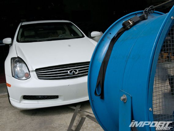
Spending thousands of dollars to properly support an aftermarket turbo kit or high-horsepower engine with a stand-alone management system is discouraging. But before desperation and thoughts of burglary cross your mind, Design Craft Fabrication of Garden Grove, CA, has discovered a more affordable solution to pricey standalone management systems, using an AEM F/IC-8 (fuel/ignition controller). When asked why Design Craft decided to integrate the F/IC-8 unit into an Infiniti G35, shop owner Gary Castillo had this explanation, "With the G35 using a drive-by-wire system, the idle and CAN-bus characteristics were not lost or compromised when the F/IC-8 was used in conjunction with the factory ECU. The only other option would have been buying an expensive stand-alone fuel management system which costs four times the amount of an F/IC-8 and would have to be programmed from scratch."
 |
AEM Engine Management System - Tech Knowledge
|
AEM Engine Management System - Tech Knowledge
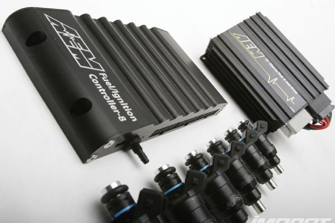
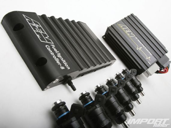
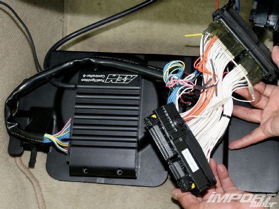
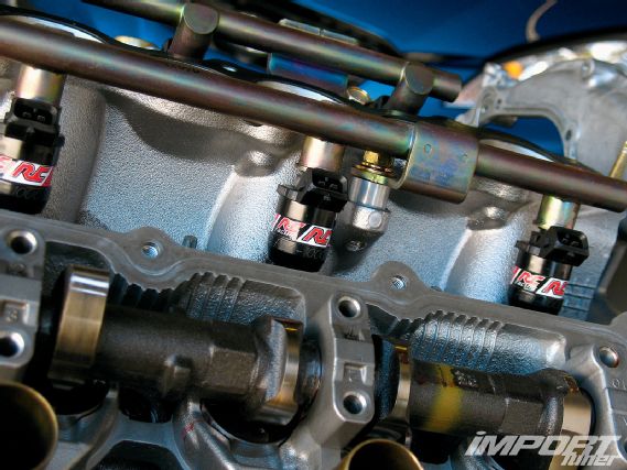
To test the capabilities of the AEM F/IC-8, we installed the device on a fully-built, twin turbo G35, along with an AEM Peak & Hold Injector Driver Module to control a set of RC Engineering 1,000 cc/min injectors. Using the supplied AEM plug-and-play G35/350Z-specific jumper harness, the F/IC-8 was integrated with the factory ECU and calibrated for additional fuel and timing, while controlling the vehicle's sensors. With many off-the-shelf piggyback management systems offering limited tuning capabilities, the F/IC is PC-programmable, allowing users to retard timing by three channels, with the capability of adding additional fuel to virtually any engine, even on variable cam timing engines including VTEC, iVTEC, VVTi, and MiVEC.
 |
AEM Engine Management System - Tech Knowledge
|
AEM Engine Management System - Tech Knowledge
Timing retard control is optimized by intercepting and delaying the outputs from the cam- and crank-position sensors to the engine, with no adverse affects on applications equipped with variable cam timing. The F/IC also has the ability to retard timing from the factory system based on engine rpm and load inputs. Our turbo G35 used the F/IC-8 to recalibrate/clamp the mass airflow sensor (MAF), eliminating a common problem among factory MAFs designed for naturally aspirated engines. Using the F/IC's on-board manifold absolute pressure sensor (MAP) allows proper fuel and ignition control in boosted conditions without affecting the signal to the ECU.
Simply slapping on two turbos without addressing additional fuel delivery is a recipe for engine failure. The F/IC-8 fuel delivery control is engineered to intercept the signal to the factory or aftermarket injectors, allowing the user to modify pulse-width by +/-100 percent. AEM engineers state, "The F/IC can decrease injector pulse-width, allowing the user to drive larger aftermarket injectors while still maintaining proper air/fuel ratios." The F/IC-8 can also be used to independently control up to eight injectors-an added bonus for those looking for big power.
 |
With the G35 using a drive-by-wire system, the idle and CAN-bus characteristics were not lost or compromised when the F/IC-8 was used in conjunction with the factory ECU
|
With the G35 using a drive-by-wire system, the idle and CAN-bus characteristics were not lost or compromised when the F/IC-8 was used in conjunction with the factory ECU
In the end, a few key strokes on the laptop and some knowledgeable tuning enabled improved throttle response, along with a boost in horsepower and torque from our G35, for the affordable MSRP of $638.00 (optional AEM Injector Driver $333.19)-a savings of over $1,000 dollars compared to stand-alone fuel management systems.
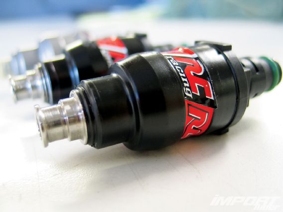
Depending on how large of an injector is needed to fuel your vehicle, performance injector companies sell saturated injectors that can flow up to a maximum of 750 cc/min. Injectors larger than 750 cc/min. require a peak-and-hold design. Since the AEM F/IC management system and factory ECU were designed to run on saturated injectors, an AEM Peak & Hold Injector Driver Module was integrated into our system to control RC Engineering 1,000 cc/min low-impedance injectors.
 |
AEM Engine Management System - Tech Knowledge
|
AEM Engine Management System - Tech Knowledge
The F/IC-8 is able to control two additional injectors by intercepting the factory injector signal to control additional injectors with its own dedicated pulse width. Outdated injector controllers would simply turn an injector on or off, offering limited control of injector flow.
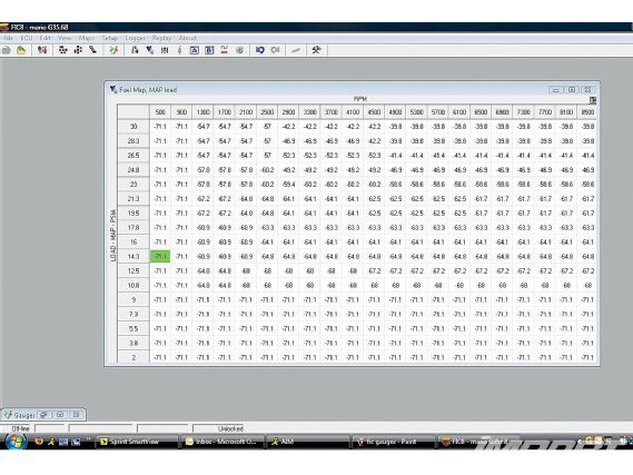
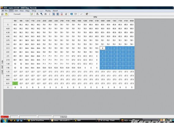
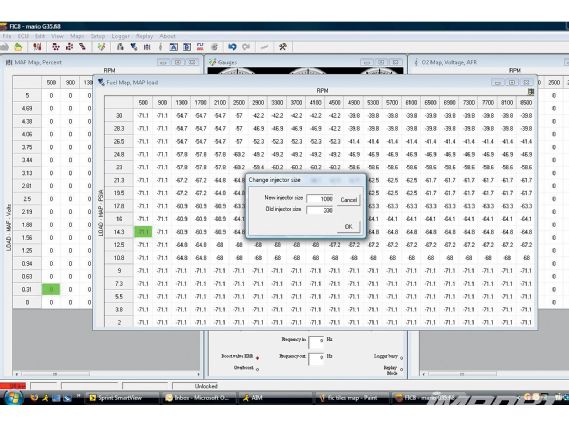
The F/IC fuel maps can be individually adjusted by cells or groups. The X- and Y-axes on the graph represent rpm and manifold pressure, respectively. Tuning with the fuel map eliminates the use of adjusting the MAF map, making the F/IC-8 respond more like a stand-alone fuel management system.
 |
AEM Engine Management System - Tech Knowledge
|
AEM Engine Management System - Tech Knowledge
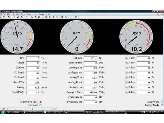
The F/IC gauge display can be set to read rpm, boost, O2 sensor, and two additional channels. Displayed on the gauge screen are the before-and-after input and output signal voltages from the MAF sensor and O2 sensor before the signal is sent to the ECU. This feature is helpful when tuning the car's MAF or MAP sensor maps.
 |
AEM Engine Management System - Tech Knowledge
|
AEM Engine Management System - Tech Knowledge
As an alternative to using the fuel maps, the F/IC can also work as a voltage modifier on the MAF, for smaller fuel changes if the user decides he doesn't want to get into the more technical side of controlling the injectors.
 |
AEM Engine Management System - Tech Knowledge
|
AEM Engine Management System - Tech Knowledge
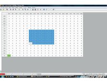
Here, the MAF X- and Y-axis graph is scaled relative to MAP sensor voltage and rpm. The F/IC is able to control frequency controlled MAFs used on vehicle such as the Mitsubishi Eclipse and Toyota Supra.
Newer, factory ECUs that enable their own wideband sensors create a problem with fuel trims from the F/IC being overridden when too rich or lean. To eliminate this problem, AEM incorporated a unique feature in the F/IC map, offering the ability to clamp the factory O2 voltage at any given rpm on the factory wideband, tricking the factory ECU into thinking everything is fine, thus allowing the F/IC to run as rich or lean as the tuner wants.
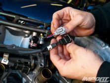
The RC Engineering low-impedance 1,000cc/min injectors require an injector clip that is available through RC.
The F/IC-8 uses quick and easy injector calibration software that allows for easy vehicle startup when using larger-sized injectors. Castillo simply input the original injector sizes into the laptop, then installed the 1,000 cc/min injectors and made the calibration change, enabling the car to fire up on the first crank.
 |
AEM Engine Management System - Tech Knowledge
|
AEM Engine Management System - Tech Knowledge
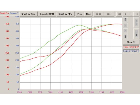
Our Infiniti G35 showed significant gains throughout low to mid rpm ranges when tuned with the AEM F/IC-8, and dyno numbers revealed an increase of 70 hp and 100 lb-ft of torque at 3,700 rpm over baseline.
 |
AEM Engine Management System - Tech Knowledge
|
AEM Engine Management System - Tech Knowledge
Peak & Hold Vs Saturated
Injectors
By Rc Engineering's John Park
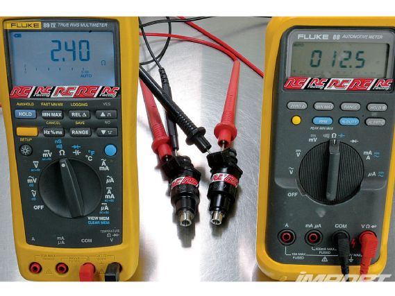
Injectors are classified under two categories: peak-and-hold or saturated. Peak-and-hold injectors are rated at 0.5-5.0 ohms (low impedance), and saturated, at 12.0-16.0 ohms (high impedance), as measured by the Fluke multimeter shown above. The type of ECU will dictate whether the vehicle uses high- or low-impedance injectors, but beware: injector types should never be mixed.
 |
AEM Engine Management System - Tech Knowledge
|
AEM Engine Management System - Tech Knowledge
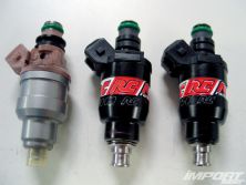
To the naked eye, distinguishing between the two types of injectors can be difficult, but when it comes to how they perform, there's no mistaking the two. The drivers in an ECU system that will handle a peak-and-hold injector will energize the injector with an initial shot of four to six amps. Once the injector is open, the current is dropped to about one to three amps to keep it open. A saturated system requires a more simplified injector driver. Unlike peak-and-hold, a saturated injector remains "on" for the entire pulse width. A high-impedance injector only needs about 1.0 amp to open and stay open. About 99 percent of fuel-injected engines on the market today will use high-impedance systems that are less complex, cost-effective and work very well for their intended use.
In the aftermarket world of high-performance gasoline engine tuning, the trend will always remain to use a low impedance system whenever possible. Some of the advantages include a wider selection of injectors, particularly when high-horsepower applications require injectors with extremely high flow rates. Other benefits include a faster response time, which minimizes the injector's "on" time, resulting in faster response to help extend the dynamic range of the injector, which proves to be especially beneficial for street cars where idle quality is a concern.
This is not to say high-performance applications should stay away from high-impedance injectors due to their slower response times. A state-of-the-art sport bike using saturated injectors can rev to 16,000 rpm without hesitation. The high revs in correlation to injection time supports that high-impedance, although slower than low-impedance, is still considered responsive enough to be capable of dealing with high-rpm demands.
How To Select The Proper Injector Size
Finding the correct injector size to support your vehicle can be found using a simple formula. As a sample, we will be using a four-cylinder engine rated at 200 hp to the crankshaft.
 |
AEM Engine Management System - Tech Knowledge
|
AEM Engine Management System - Tech Knowledge
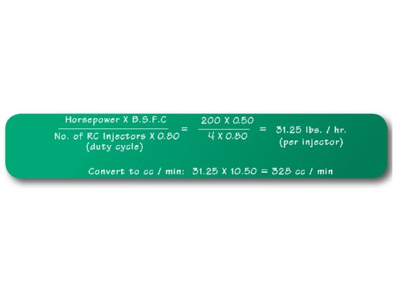
First, we need to determine the B.S.F.C (brake specific fuel consumption). B.S.F.C is the amount of fuel an engine needs to make X amount of power (the lower the number, the more efficient the engine). The B.S.F.C varies, depending if the car is naturally aspirated or turbocharged. For naturally aspirated cars, the B.S.F.C. will be anywhere from 0.45 to 0.50, meaning the engine will use 0.50 lbs of fuel per hour for each horsepower it produces. For turbocharged engines the scale will be at 0.55 to 0.60 lbs per hour or higher, depending on whether the engine is running on pump gas or race fuel. If the car is running race fuel, the B.S.F.C. is slightly lower.
1. Take the target horsepower at the crankshaft (i.e. 200 hp) and multiply that number by the B.S.F.C (0.50) =100.
2. Take the number of injectors (4) multiplied by the injector duty cycle (0.80) = 3.2.
3. Finally divide the 100 by 3.2 = 31.25 lbs/hr is the total per injector.
4. To convert from lbs/hr. to cc/min, multiply 31.25 by 10.50, to get 328cc/min.
5. The proper injector size for this application would be 31 lbs/hr or 330 cc/min.