LS engine swaps have become fairly common in the classic truck world, but it seems there still exists a bit of mystery surrounding what it actually takes to retrofit an old hauler with modern motivation. Electrical requirements, wiring necessities, and component cooperation are all considerations that need to be investigated before a modern motor can be dropped between the 'rails of your classic pickup. Fuel system requirements, gauge package compliance, and plain old fitment all need to be thought about ahead of time.
And while the sensor package of a modern engine can at first appear daunting, it's actually pretty foolproof when it comes to hooking things up. On our Chevy Performance Parts LS327, for example, all of the necessary sensors attach via different connectors, therefore making it impossible to connect say, the MAP sensor to the crank sensor wire connector. Coupled with a wiring harness like Holley's LS1 Main Harness truly makes this a plug-n-play affair, mating all the connectors to the ECU. Once all the connectors are mated to their respective sensor, you're left with only a handful of loose wires to connect to the truck's main harness.
The specific sensors that our engine will require come down to engine management. In our case we'll be using the Holley Dominator Vehicle Management System to control and manage the 327 in a Speed Density format. Simply put, a Speed Density system compiles information from a handful of sensors to determine engine speed and load, and then extrapolates that information, combined with a preprogrammed fuel map to establish the engine's fuel needs. Engine speed is determined via a tach signal, while load is established by using the vacuum created by the intake, read via a Manifold Air Pressure (MAP) sensor (we'll be using a 2 Bar MAP sensor for our supercharged setup). An Intake Air Temperature (IAT) sensor also throws its info in the mix by reading the air temperature inside the intake, thereby determining any air density changes. A pair of wideband O2 sensors, one behind each exhaust manifold, adds fuel/air ratio information to the game and allows the ECU to make any necessary corrections to the mix as determined by the initial tune.
Typically, a Speed Density system would also require an Idle Air Control (IAC) Motor to maintain proper idle speed and a Throttle Position Sensor (TPS) to communicate actual throttle blade position to the ECU. Our setup, however, will take advantage of the fact that the Holley Dominator system can fully control a GM Drive-By-Wire (DBW) throttle body setup, with Holley's plug-and-play DBW harness which allows the Holley Dominator ECU to control the throttle blade position for idle speed control and read the internal throttle position sensors to eliminate the need for an external IAC and TPS sensor. To keep our engine from becoming a pile of parts spat out through the oil pan, we'll also be incorporating a coolant temperature sender (CTS), oil pressure sender, and two knock sensors mounted in the valley of the engine. This will provide fair warning that something might be going a bit pear shaped and allow the computer to pull out timing, cut fuel delivery, or both to avoid a potential catastrophic result.
At the end of the day, I will admit that it is a bit to get one's head 'round, but the good news is, you needn't understand it fully. A simple comprehension of what sensor does what job and why, followed by a simple mix-and-match affair with the wiring harness, and the hard bit is better left to sharper minds than mine. Once we had everything connected and powered up, I loaded one of the custom calibrations provided by Holley in their EFI software, entering in our engine parameters to further determine a more accurate base tune. Once all the numbers jived with our engine's setup (firing order, DBW, 24-tooth reluctor wheel, speed density load sensing, etc.), a reluctant push of the starter button and the LS roared to life, reacted to pedal inputs, and after a quick warm-up period, settled down to a nice, steady idle. I couldn't have been more impressed. The self-learning feature of the Dominator meant that with this base map loaded, we could proceed to drive the '68 around immediately, all the while teaching the computer the necessary fuel parameters that the blown engine required. After a short break-in period, we then took the truck to Westech Performance Group, where the engine was then carefully tuned to reach its full potential before being mercilessly flogged on their chassis dyno. We'll reveal the impressive numbers next month as well as a more in-depth look at the combo that it took to get there. For now, check out what it takes to make a 21st century supercharged LS engine tick.
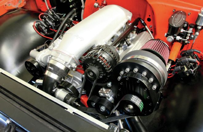
| Chevrolet Performance Parts Ls327 After We Dropped It Into The C10
01 Here's our supercharged Chevy Performance Parts LS327 just after we dropped it into the C10. The fuel lines are hooked up, and the preliminary wiring is in place. Now it's time to hook all the sensors up that will make our motor come alive.
| Holley Dominator Vehicle Management System Components
02 To control the LS327, we'll be using Holley's Dominator Vehicle Management System (#554-114). The Dominator not only provides the fuel map for the engine, but will control the ignition side of things as well. It will also control the DBW throttle body and pedal. The capabilities of the Dominator EFI system are truly vast and we merely scratched the surface when it came to its capabilities. Multiple mappable inputs and outputs can be configured in a variety of options to control a myriad of components including water/meth injection, electric fans, fuel pumps, A/C inputs, and more. We assembled the ECU along with the necessary wiring harnesses on our bench before we mounted it permanently inside the cab. From left are the power harness (#558-308), DBW harness (#558-406), and the main harness (558-102). Coiled in between the main harness is an auxiliary harness (#558-404) used to add additional inputs and outputs to the system as needed.
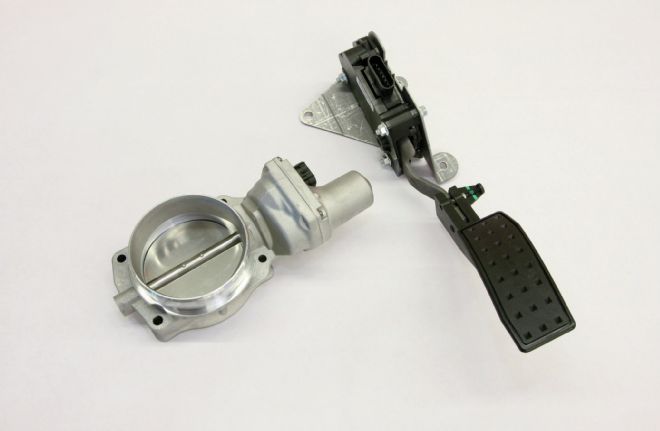
| Gm Drive By Wire Throttle Pedal And Throttle Body
03 For our engine, we're going to take advantage of the Holley Dominator's ability to control a GM drive-by-wire throttle pedal and throttle body by using a two-channel GM throttle body (GM #12570790) controlled via a DBW pedal (GM #10379038). Using a DBW setup eliminates the need to fabricate up a throttle cable system, making the install a simple plug-n-play affair. Using Holley's EFI software, we'll be able to tune the pedal versus throttle opening to fine tune the driving characteristics of our truck.
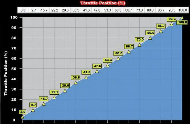
| Pedal Versus Throttle Position Table
04 The Pedal versus Throttle Position table is the primary method of "tuning" a DBW throttle body system. The "Pedal Position" represents the position of the accelerator pedal. The user can adjust the "Throttle Position" to change based on the pedal position. This allows the user to increase or decrease throttle body position (engine airflow) to tailor the "responsiveness" of the engine. It can allow for an overly large throttle body to have good driving manners or a small throttle body to be very responsive. For example, if a vehicle is not responsive enough off-idle, increase the throttle position at low pedal positions. If a vehicle has too much throttle response, lower the throttle position accordingly.
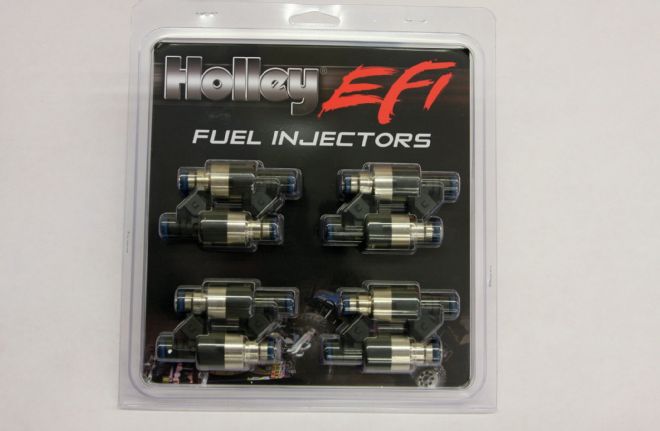
| Holley Efi Fuel Injectors
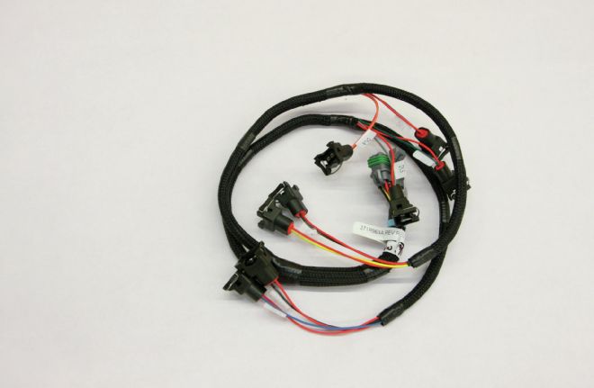
| Holley Bosch Style V 8 Injector Wiring
05-06 We'll be using eight Holley 42 lb/hr fuel injectors (#522-428) for our setup, mounted directly over the intake ports and triggered by the Dominator ECU via Holley's Bosch-style V-8 Injector Wiring Harness (#558-200).
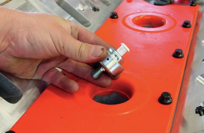
| Gm Knock Sensor To Be Mounted In Factory Location In Vallet Of Engine
| Gm Knock Sensor Being Mounted In Factory Location In Vallet Of Engine
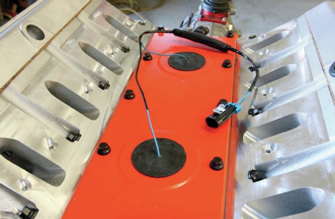
| Gm Knock Sensors Mounted And Wired Up
07-09 Two GM knock sensors (GM#12589867) will be mounted in the factory location in the valley of the engine to detect any foul activity inside the motor. They will communicate with the Dominator ECU via a knock sensor wiring harness (GM#12601822).
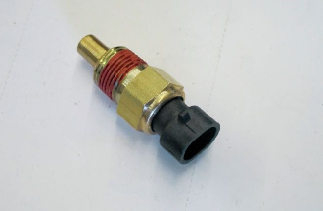
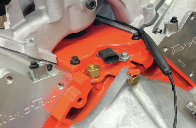
| Coolant Temperature Sensor
10 A coolant temperature sensor (#534-10) will be mounted in the passenger's side head to keep tabs on the engine's temperature.
| 0 100 Psi Oil Pressure Sensor
11 The final link in the safety chain is the 0-100 psi oil pressure sensor (#554-102). Between the CTS, oil pressure sensor, and the knock sensors, any undesirable engine state will be noticed by the ECU with appropriate changes made to the fuel/ignition system to hopefully thwart total annihilation of the engine.
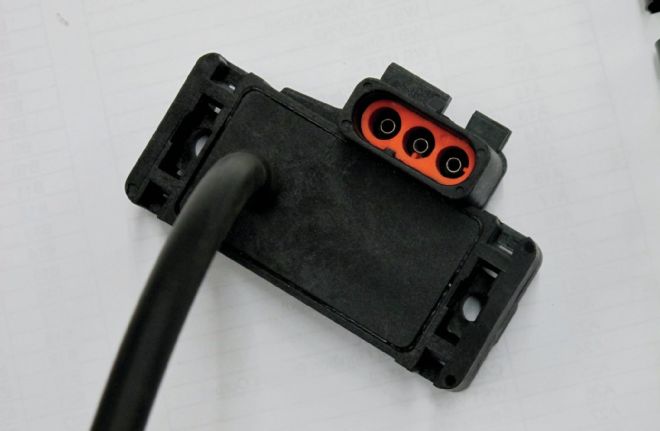
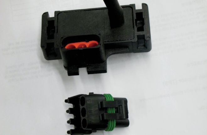
| Holley Dominator System 2 Bar Map Sensor
12 The Holley Dominator system uses Speed Density to control the fuel/spark of our engine by compiling the information received from a number of sensors. One is the 2-bar Manifold Air Pressure (MAP) sensor (#538-13). Since one bar is equivalent to the weight of one atmosphere at sea level, or 14.7 psi, adding another 8 psi from to the supercharger brings the total pressure up to 22.7 psi, hence the 2-bar MAP sensor. If we were to add more boost and push the adjusted psi over, say 29 psi, we'd need a 3-bar MAP sensor. The MAP sensor detects the pressure inside the intake manifold and responds to changes in manifold pressures (vacuum or boost), relaying the information to the ECU.
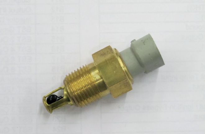
| Intake Air Temperature Sensor
13 The Intake Air Temperature (IAT) Sensor (#9920-107) monitors the temperature of the air entering the intake of the engine. Colder, less dense air requires more fuel to maintain the same air/fuel ratio than hotter, denser air.
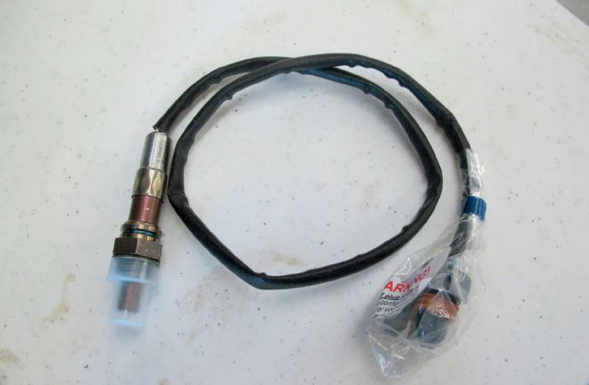
| Ntk Wideband O2 Sensors
14 A pair of NTK Wideband O2 Sensors (#554-100) will be used to ensure that the information coming from the MAP and IAT sensors is accurate and being processed properly by the ECU. An improper air/fuel ratio detected by either O2 sensor means either a malfunction of the IAT or MAP sensor, fuel injectors, throttle body, ECU, or any combination of those items. In a way, the O2 sensors are the last "check" to ensure that the engine is combusting the fuel as efficiently as possible.
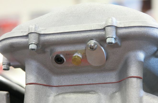
| Three Parts On The Back Of The Holley Mid Rise Location On Engine
15 With the sensors identified, let's take a look at their location on the engine. At the back of the Holley Mid-Rise intake manifold (#300-135) that we'll be using are three ports. The port on the far right is for an LS3-style MAP sensor. These are a direct mount and don't require a barbed fitting and hose to receive signal. Ours MAP sensor does, so a block-off plate was fabricated and installed in place of the LS3-style sensor. At the moment, all the ports are blocked off to prevent debris from entering the intake as we're installing the engine. The 1⁄4-NPT port on the left will accept the IAT sensor while the 1⁄8-NPT port in the center will be equipped with a barbed fitting to which a hose will be attached to provide the boost/vacuum reference to the MAP sensor.
| Npt Port To Provide Boost Vacuum Reference For The Boost
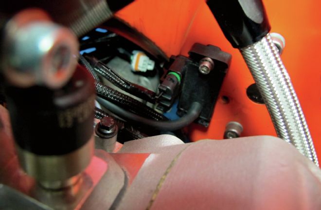
16 Just below the plenum of the intake is another 1⁄4-NPT port, which will provide boost/vacuum reference to the boost gauge as well as the fuel regulator. Providing a boost reference signal to the regulator is important as the fuel demands can increase as the engine is under a boosted situation. Note the wiring harness for the knock sensors exiting from underneath the intake manifold as well. Down at the back of the block are two items worth mentioning. The first is the oil pressure port on the left. The other is the Camshaft Position Sensor, which will mate with the matching connector on the wiring harness.
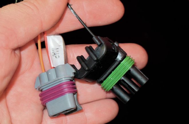
| Holley Wiring Harness Deutsch Style Map Sensor Connector For Ls3 Sensor
17 Our Holley wiring harness came equipped with a Deutsch-style MAP sensor connector for the aforementioned LS3 sensor. Since we'll be using the earlier-style sensor, we'll need to swap out this connector with the other style.
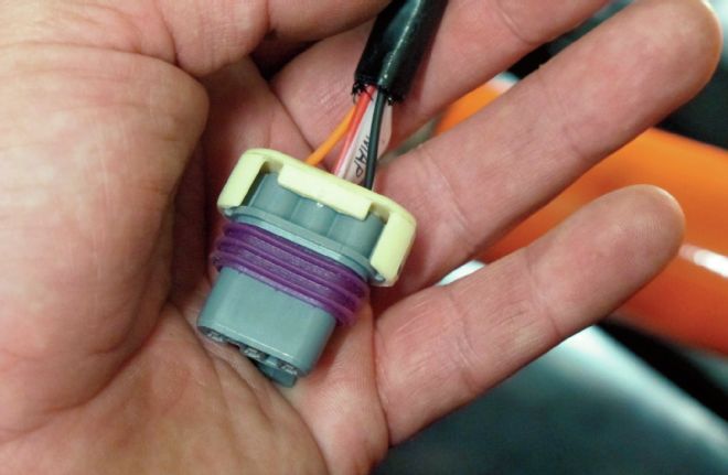
| Map Sensor Pin Style Weather Tight Connector
18 Luckily, our MAP sensor came with a pin-style weather-tight connector for just such an occasion.
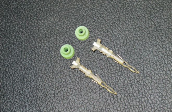
| Pin Style Terminals
| Connectors
19-20 Swapping the connectors is simply a matter of cutting the wires and recrimping them using the new pin-style terminals.
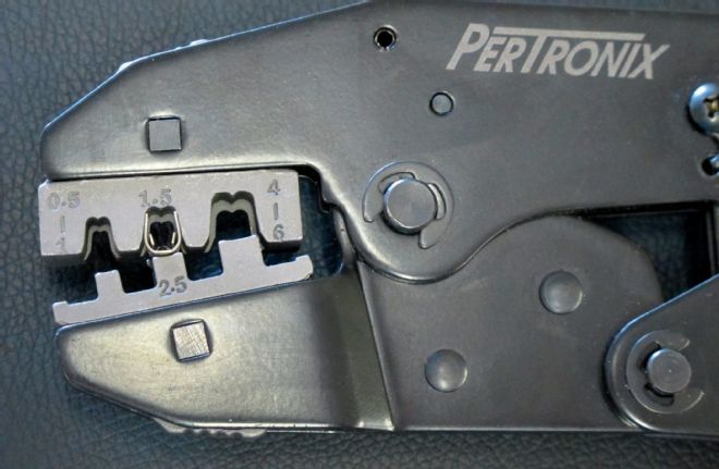
| Pertronix Crimping Tool
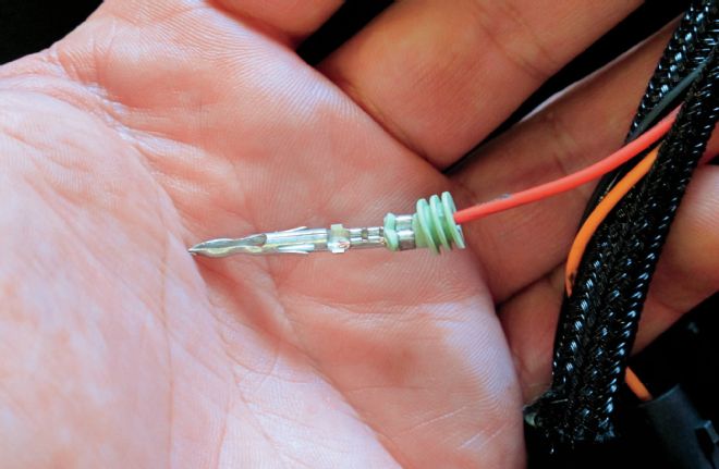
| Pin Style Terminal Crimped On Wire
21-22 I've been using PerTronix's crimping tool for all the wiring on my '68 and it works exceptionally well for these type of connectors.
| Map Sensor Mounted On The Firewall
23 The MAP sensor was mounted on the firewall, directly behind and below the intake to keep the vacuum hose as short as possible.
| Holley Wiring Harness Connectors Not To Be Used
24 Since we'll be utilizing a Drive-By-Wire setup, there are a couple connectors in the Holley wiring harness that won't be used, namely those for the TPS and IAC sensors. I'm also not concerned with monitoring the fuel pressure, so we'll be taping that connector back into the loom as well.
| Holley Wiring Harness Connectors To Be Used
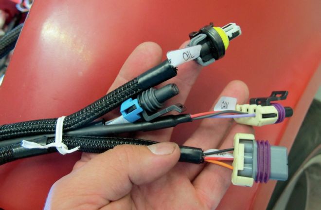
25 We will be using a number of other connectors, however. Here, you can see the connectors for the oil pressure, camshaft position, MAP, and IAT sensors. This group of wires will be routed to the back of the engine where the corresponding sensors are located.
| Crankshaft Position Sensor On Passenger Side Of Ls327 Engine Block
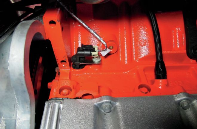
26 The Crankshaft Position Sensor is on the passenger side of the block, just above the starter. This monitors the position and rotational speed of the crankshaft to control ignition timing and other engine parameters.
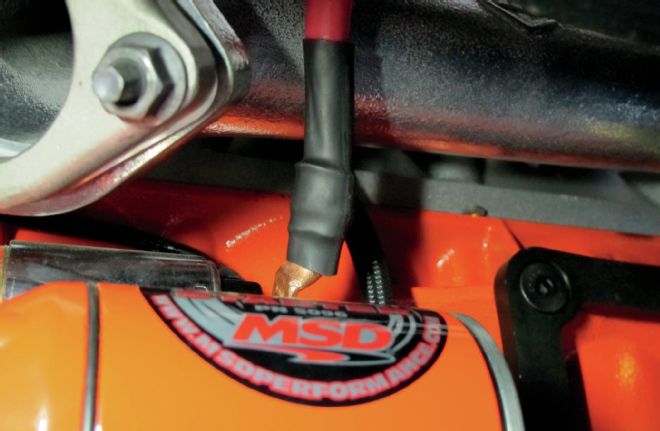
| Msd Performance Starter Installed
27 Once the Crankshaft Position Sensor is hooked up, we installed the MSD Performance starter (#5096) and its associated wiring. For our project, we linked the battery directly to the starter, while the solenoid was wired to the purple (#919) wire on our Painless Performance wiring harness.
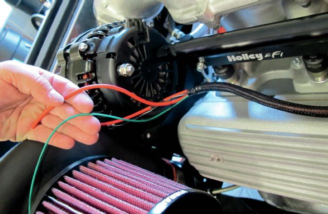
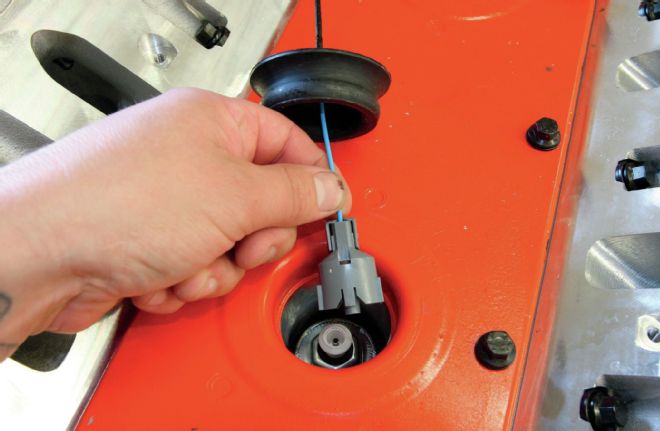
| Wires That Need To Be Connected To Other Parts Of The Engine
28 Speaking of the Painless wiring harness, we might as well cover the couple other wires that need to be connected to the engine. The red wire in my hand (#915) will be attached to the alternator post. A separate six-gauge wire will also be attached to the alternator post and run to one side of a 200-amp MIDI fuse. The other red wire (#916) will also run to this main fuse, providing 12-volt battery power to the main harness and fuse block. That green wire (#983) attaches to a temperature sending unit and the barely visible black and white wire (#902) connects to the A/C compressor.
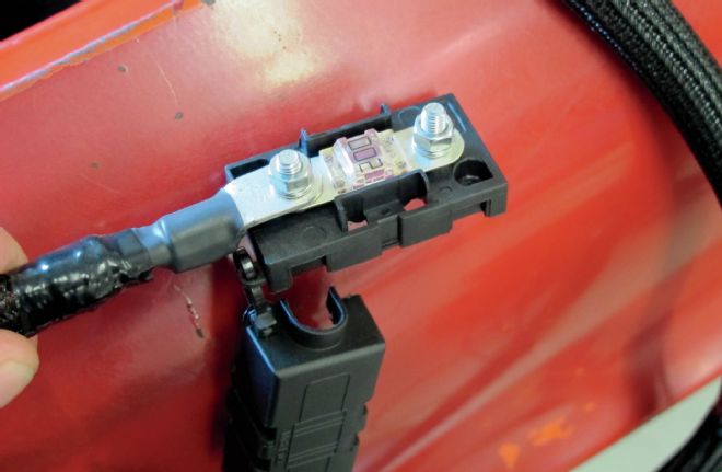
| 200 Amp Midi Fuse
29 Here's the 200-amp MIDI fuse that will serve to protect our entire electrical system. It will be mounted near the battery with a number of other fuses for the Holley ECU, stereo amps, etc.
| Wire Connected For Gauge Cluster
30 Since the ECU requires its own temperature and oil pressure sending units, which we covered earlier, we need to have another pair to provide the same information to the Classic Instruments gauge cluster. That green wire (#983) previously mentioned is attached to a standard temperature sending unit mounted in the driver's side head for just this reason.
| Gauge Cluster Engine Oil Pressure Reading Wire
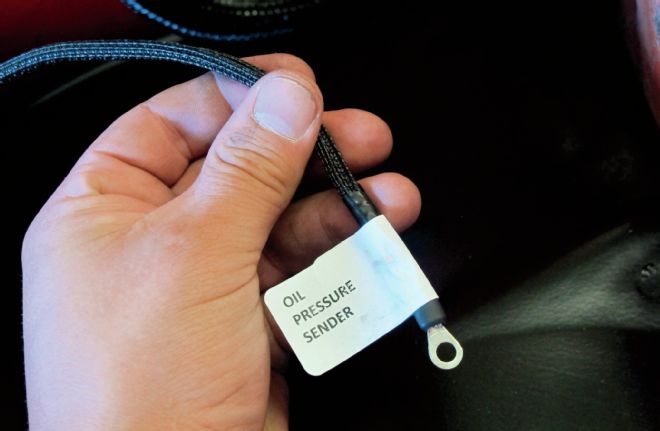
31 To provide the cluster with an engine oil pressure reading, another separate wire (#922) that's part of the main Painless engine compartment harness connects to the pressure sending unit. Circuit labels are provided in the Painless kit so that wires can be labeled, set aside, and connected at a later date.
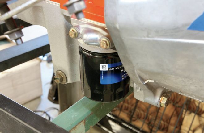
| Wire Port For Cluster Gauge Wire Above Oil Filter
32 Since the ECU is using the oil port at the top of the block, we need to find an alternative for the oil pressure gauge's sending unit. Above the oil filter on the driver's side is a port that is blocked off from the factory on our crate engine, but can be converted for just such an occasion.
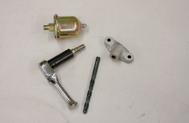
| Q Sized Drill And Sending Unit Components
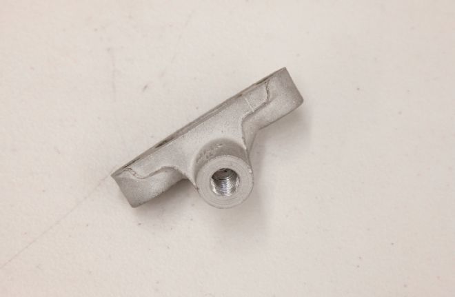
| Sending Unit Part
33-34 Swapping the blank block-off plate with a modified GM oil pan side cover (#12577903) allows us to tap directly into the oil pressure port for our sending unit. The side cover has a blind hole machined in the upright portion of the casting that needs to be drilled through to the backside first so as to tap into the oil port. A "Q" (0.332-inch) sized drill is used since the follow up procedure calls for tapping the hole to 1⁄8-NPT to correspond with the fitting on the sending unit.
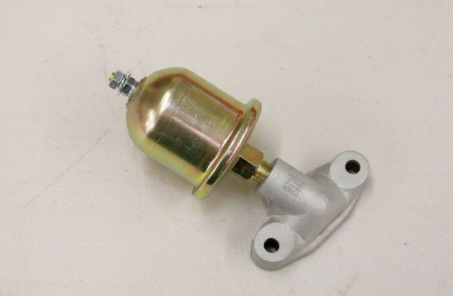
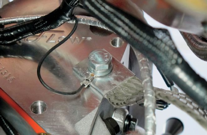
| Machined Sending Unit Assembly
35 Once machined, the sending unit can be installed, using a little thread sealant, before the whole assembly is swapped out with the block-off plate and the oil pressure wire (#922) attached.
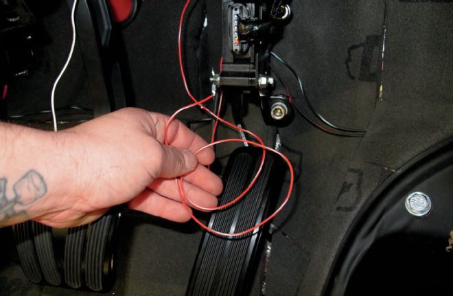
| Wire For Brake Pedal Switch Input Safety Circuit
36 Inside the cab, once the DBW harness is attached, another single wire needs to be connected. This is the brake pedal switch input safety circuit and needs to be attached to the 12V+ input on the brake pedal switch. When the brake pedal is depressed enough to activate the brake light switch, the ECU will not allow a pedal position over 10 percent, no matter how far the pedal is pushed. This consequently limits the opening of the throttle body. This is a fail-safe circuit and is required as part of the Drive-By-Wire feature. Note the dressed up GM throttle pedal, thanks to the addition of a Lokar Direct-Fit Throttle Pedal Pad (#XDBW-6200) that matches our existing clutch and brake pedals.
| Painless Performance Chassis Harness Ground Kit
37 Proper ground connections are extremely important in any wiring job, especially one that involves sensitive computer equipment and sensors. To ensure everything is properly grounded, we'll be using Painless' Chassis Harness ground kit (#40140) to ground the cab to the chassis, as well as to the engine.
| Holley Wiring Harness Wire Grounded To Head Bolt
38 The Holley Wiring Harness includes one wire at either side of the engine that needs to be grounded to each individual head. On the passenger side using the same head bolt, I then used the heaviest strap of the Chassis Harness ground kit to ground the engine to the frame.
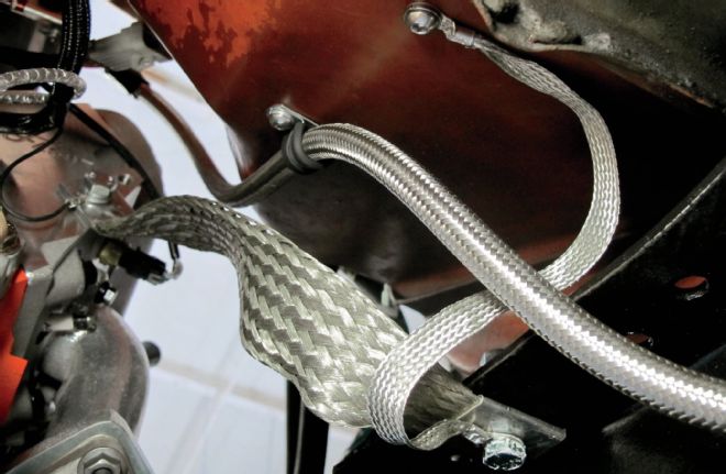
| Strap Mating The Cab To The Frame
39 I then used another strap to mate the cab to the frame. Attached to the same frame bolt will be the main ground cable that will attach to the negative side of the battery. Note how the grounds are all "linked" together. Inside the cab, all the grounded wires run to the 1⁄4-20 bolt visible at the end of the smaller cab ground strap. A similar setup exists on the driver's side as well to provide easy access for grounding points for the gauges, keyless entry, and other various electrical components.
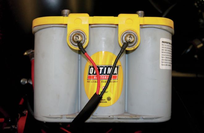
| Optima Yellow Top Battery Wired Up Correctly
40 In addition to the proper grounding requirements, it is imperative that the Holley Dominator ECU is wired directly to the battery using the provided 10-gauge wire power harness. A 40-amp fuse is pre-installed to prevent damage to the ECU. I've found that the side mounts on the D34/78 battery models work perfectly for this. To provide the necessary battery power for our energy hungry C10, we'll be using an Optima Yellow Top (#8014-045) high-performance absorbent glass-mat battery. With 750 cold cranking amps at the ready, the deep cycle design is built to handle the high-demand loads that we'll be throwing at it.