 Christian Hazel
Brand Manager, Four Wheeler
Christian Hazel
Brand Manager, Four Wheeler
As a kid growing up in Massachusetts, I watched a lot of cartoons while snowed-in during winter. Though at the time I didn’t know who Rube Goldberg was, the guys who created the cartoon characters Tom and Jerry surely did. One of my favorite cartoon episodes, Designs on Jerry, follows Tom the cat as he designs and builds an overly complicated Rube Goldbergesque mousetrap to catch Jerry the mouse. Once triggered, the mousetrap meandered and plodded through a series of unnecessarily complex moves all over the room until finally springing the part of the device supposed to catch Jerry. Naturally, it didn’t work. It’s much like the factory Ross cam and lever steering in most ’71-earlier Jeeps.
There’s the huge steering wheel connected directly to the worm shaft which rides on tiny little ball bearings in a sheetmetal cage on the top and larger ball bearings in the steer gear on the bottom. The sector shaft indexes on the worm gear with a grinding metal-to-metal connection of its two sector shaft pins and is supported inside the steering gear case by soft-metal bushings. A drag link with wear-prone ball-and-socket ends connects on one side to the pitman arm, and on the other, to the bellcrank. The bellcrank is mounted under the radiator to the pivot via either soft metal bushings or wear-prone caged needle bearings. Finally, a two-piece (left and right) tie-rod setup ensures the toe will change on every bump and dip in the road. In all, input from the steering wheel is really more of a suggestion to the front tires than a command. And the expected service life of many of the components, even with regular greasing, adjusting, and maintenance, isn’t much more than the lifespan of a set of modern radial tires. Every point in the system invites wear and wander.
It’s no wonder that power or manual Saginaw conversions were and still are so popular on these old vehicles. But that’s all on the one hand. On the other hand, the cam-and-lever setup on these vehicles is a design proven by literally 75 years of use. And for whatever reason, not every old Jeep owner wants to deviate from stock. Such was the case with my ’54 M-170 ambulance. I didn’t want to drastically modify this little slice of history of which I found myself caretaker. I deemed a rebuild of the factory steering components would be more than adequate to carry out this vehicle’s mission of cruising around town and driving through the mountains to bump down the occasional moderate desert trail.
Despite being in production for 30 years, you just can’t just go into any local auto parts store for rebuild parts for one of these steering systems. I browsed the Omix-ADA catalog and came up with nearly all the replacement parts I needed for the job. Unfortunately, the M38A1 and M-170 use a few slightly beefier and more obscure parts than the earlier military and civilian Jeeps, so I needed to track down a good used sector shaft and worm gear since mine were kinda fubar. Otherwise, Omix had all the parts in stock to rebuild my (or your) factory steering. Use the following as a loose guideline, but if you’re building or restoring an early Jeep, you should pick up a copy of Bentley Publishers’ Jeep CJ Rebuilder’s Manualby Moses Ludel. It’s like a factory service manual for your old Jeep restoration.
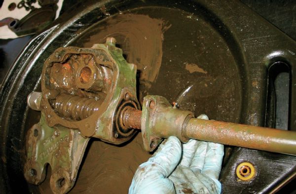
The bellcrank bearings or bushings are an area of high wear. Repair kits that include new bushings or bearings, pivot, and seals are readily available, but the pivot sizes changed over the years. We disconnected our worn tie-rod ends and drag link and then unfastened the pinch bolt before unthreading the pivot from its mount. Remove the bellcrank as an assembly.
Give the needle bearings a good coat of quality grease and insert the pivot into the bellcrank. Reinstall in the chassis and torque the pivot bolt to 70-90 lb-ft. You want the bellcrank tight, but still able to pivot freely back and forth. We zapped the zerk with some quality full-synthetic Royal Purple Ultra-Performance axle grease.
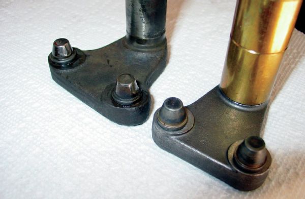
Our old bellcrank pivot (left) was a bit scored and the caged needle bearings were totally worn out, allowing the bellcrank to flop around a bit. The new Omix bellcrank kit (PN 18042.03), includes a new pivot, bearings, seals, and hardware. The difference in pivot diameter is made up with a sleeve on the new part.
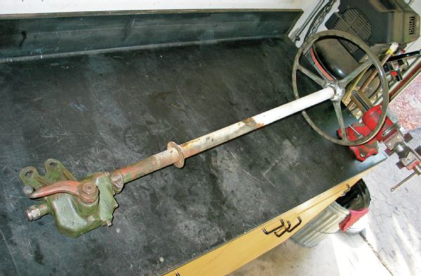
On V-6 models the clearances are a tad tighter, but on F-head-equipped Jeeps you should be able to remove the steering gear and column as an assembly after removing the throttle linkage, floor cover plates, and pedals. We used a wire wheel to clean off the decades of accumulated dirt and grease and got to work.
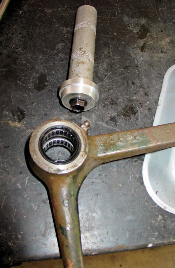
You want to insert the caged needle bearings squarely inside the bellcrank bore, making sure not to cover the grease zerk. Drive them in just enough so the grease seals (shown here installed) fit cleanly in the bores. A dedicated seal-driving tool will give the best results.
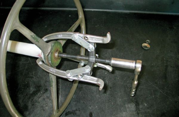
Without fail, the only way we’ve been able to get a vintage Jeep steering wheel off is with a three-jaw puller. Just be careful with the jaw placement on the underside of the wheel, since it can deform or chip the material. A two-piece wooden collar cut to snugly fit the underside of the wheel would help prevent this damage if you’re dealing with a nice Jeep. We weren’t.
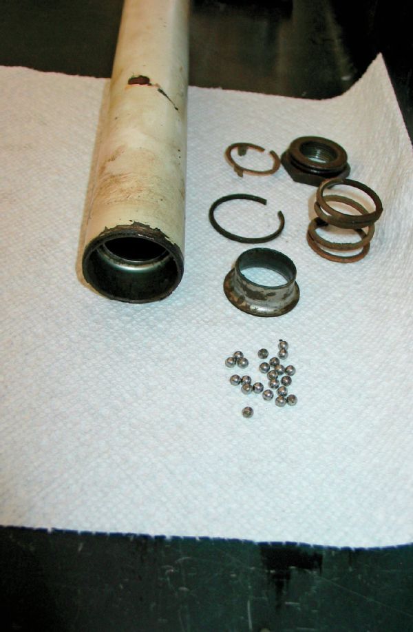
With the steering wheel off, the column tube can be removed and the upper bearings and race removed and inspected. Most of our ball bearings were missing and our race was pretty hammered, so we used a new steering column bearing kit from Omix (PN 18030.02).
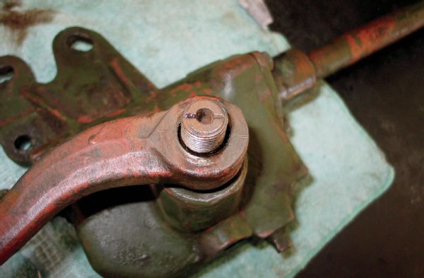
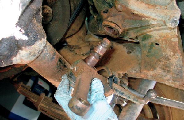
Before using a pitman arm puller to remove the pitman arm, make sure the factory part is scribed so it can be reinstalled with the proper indexing. Ours sported these factory marks, but if not, you can use a simple center punch to make three dimples to line it up when you put it back together. Don’t use marker or anything that can get washed off with grease or solvents.
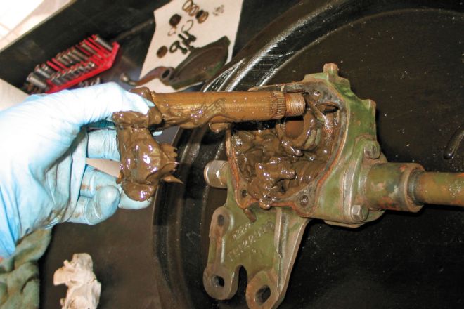
Flip the box over and release the tension on the sector shaft adjustment set screw, remove the cover, and take out the sector shaft (lead photo). Then, you can remove the upper cover (shown) and carefully remove and clean all the shims for reuse.
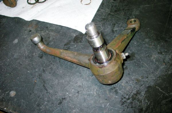
Note the wear on our original sector shaft’s pins (arrows). Differences in sector shafts through the years were in the sector shaft diameter at the steering box, sector shaft length at the shaft, and distance between the pins. Shown is a new ’50-’52 M-38 sector shaft from Omix (PN 18027.02) with the right height and diameter, but not the proper pin offset. We couldn’t find a source for a new sector shaft, so instead we had a machine shop press out and rotate our old pins so fresh area contacted the worm gear.
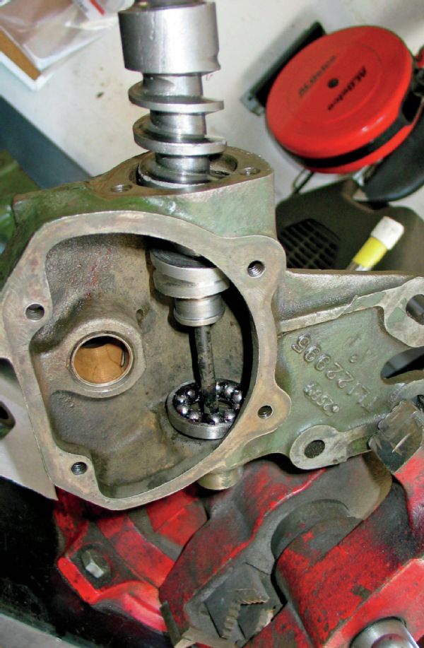
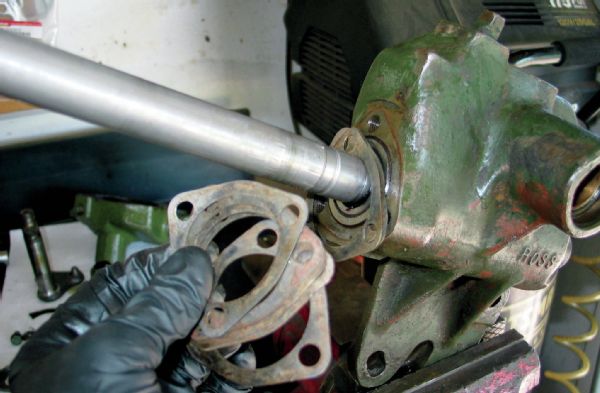
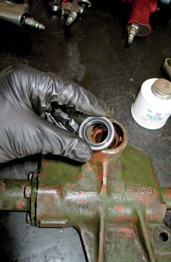
Reinstallation goes down the opposite of disassembly, but you wanna set the ball bearings in their race inside the box and then feed the worm gear through, installing the snap ring and seating the shaft in its bore. We used a new steering gear box worm shaft bearing kit from Omix (PN 18029.01). Note the original bronze sector shaft bushing we left in place.
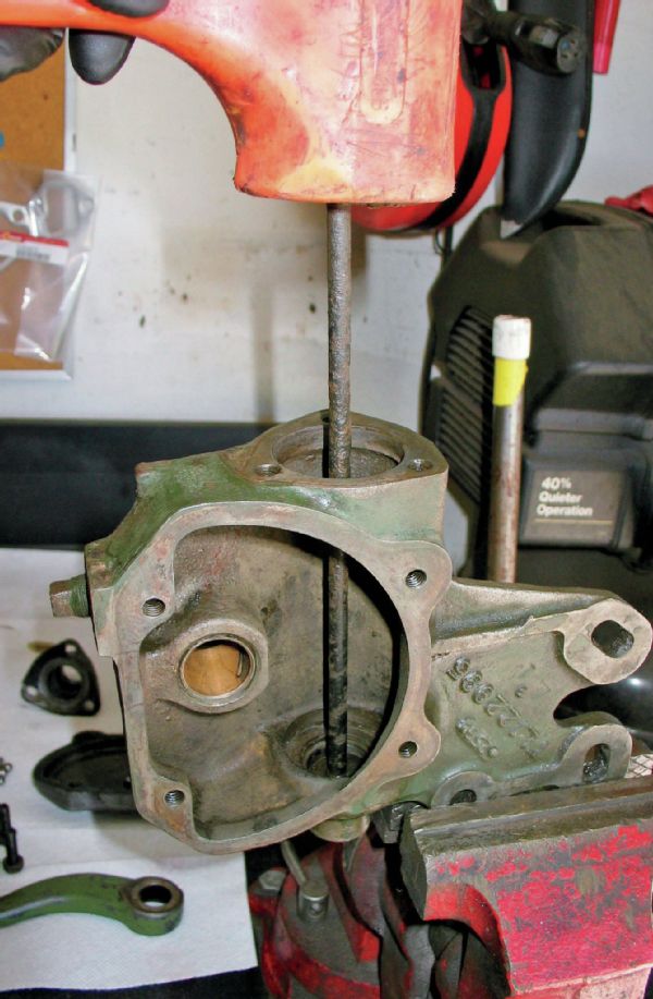
The worm gear comes out after removal of several snap rings and the lower bearing assembly. Once you get the box stripped, clean and inspect the sector shaft bushing. If there was a lot of side-to-side play in the sector shaft, you’ll want to have a new bushing pressed in and reamed to proper size by a local machine shop. The bushings are soft bronze and distort when installed, so the reaming is a required step. Ours was okay, so we just installed a new Omix sector shaft seal (PN 18029.03).
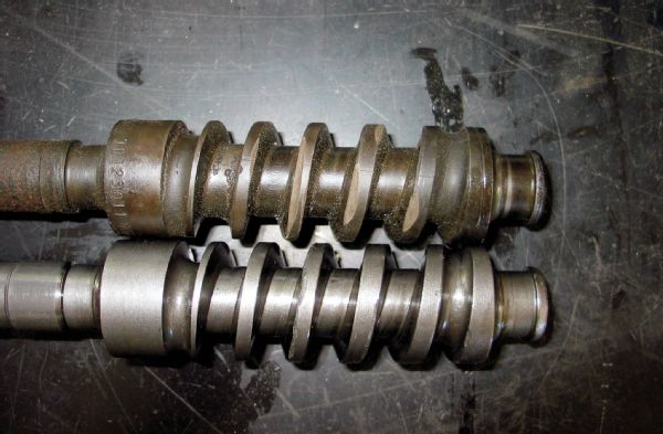
Another frustration came from chipped teeth on our original worm gear (top). We wound up buying a good take-out steering box from a buddy’s M38A1 just for the good worm shaft. Had that option not been available, we could have tracked down an M38 worm shaft for use with the new Omix M38 sector shaft we had.
With the upper bearing installed, we adjusted the shims that go under the top cover. There’s no real preload value, but you want to eliminate all up-and-down play in the shaft while still allowing it to turn with only very minor resistance. The Moses Ludel book suggests using a spring scale on the shaft to measure 1⁄2- to 3⁄4-pound preload.
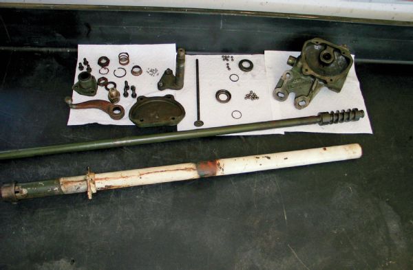
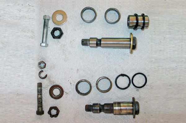
Here’s a Ross steering system all laid out and cleaned for inspection. We had some minor wear on the ball of the pitman arm, but it was still serviceable. Most of our ball bearings and races were shot, but new parts from Omix were available for them. The sector shaft pins and worm gear teeth were another matter.
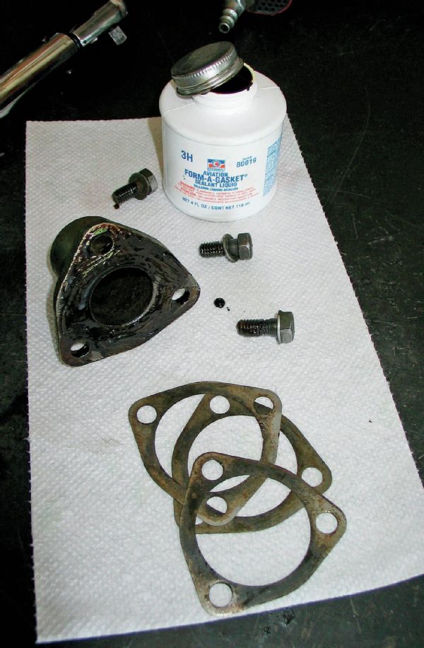
Once we got the shim stack right, we coated the shims and retainer bolts with Permatex Aviation Form-a-Gasket and torqued the cover to place to 20 lb-ft.
We installed a new sector shaft seal and then inserted the sector shaft with the pins on the worm gear roughly centered in the box and filled it with synthetic grease. We used some Form-a-Gasket on a new cover gasket and torqued the cover bolts to 20 lb-ft with the adjusting screw completely removed from the cover.
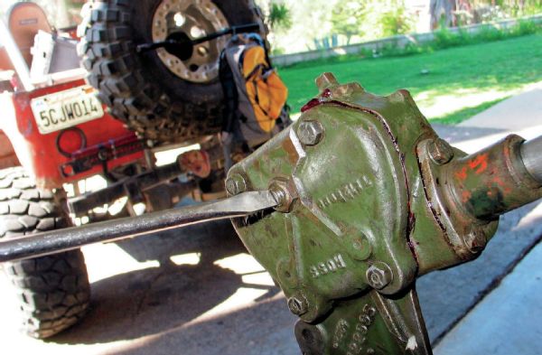
We turned the shaft all the way left-to-right in each direction, counting turns as we went so we could back it up to dead center. With the sector shaft in the center of the worm gear, we reinstalled the adjusting screw and gently seated it against the sector shaft to remove any runout. Then we locked the set screw nut down, reinstalled the steering tube, upper bearings, and steering wheel, and reinstalled it in the vehicle.