 Ali Mansour
Brand Manager, 4WD & Sport Utility
Ali Mansour
Brand Manager, 4WD & Sport Utility
Degree, travel, and constant velocity might sound more like physics homework than 4x4 jargon, but don't be confused, for it's all basic terminology associated with your vehicles driveshaft. Driveshafts are the crucial rotating members that deliver power from the transfer case to the differentials. While their basic function may appear elemental on the surface, a lot of time and technology goes into building a quality driveshaft.
At the OEM level, driveline development generally circles around the driveshaft's weight, material cost, and safety characteristics. The aftermarket, on the other hand, has to factor in similar concerns in addition to accommodating modified vehicles and the harsh off-road environments that they are certain to face. With so many vehicle uses and applications it's nearly impossible to pick which driveshaft is the best across the board, but there are a generalities and specifications that most high-quality drivelines are crafted around.
Likely the most used and installed shaft type currently is the CV (constant velocity) style driveline. To get a closer look at some of the parts and pieces that make up these modern drivelines we took a trip to the driveshaft experts at J.E. Reel in Pomona, California. There, we went over the modern drivelines and even grabbed a spy shot of what might be a future solution for off-road vehicles dealing with extreme driveline angels.
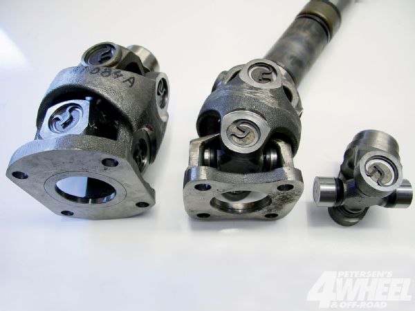
The Constant Factor
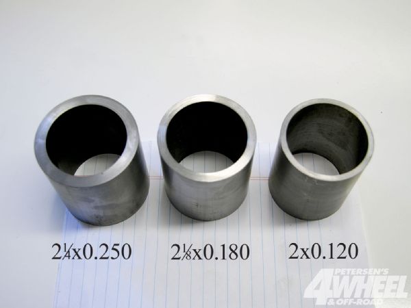
Most lifted vehicles require the addition of a CV (constant velocity) joint. When a standard U-joint driveline cycles and changes its angle, it actually changes speed to faster and slower. The CV allows the shaft to remain at the same speed so as not to disrupt the rotation and to prevent vibration. The two most common CVs are the larger 1350 (left) and the standard 1310 (center). While a non-CV-style shaft (right) is extremely strong and will allow for more degree change over a CV joint, it can cause extreme vibrations when operating at high rpm and angles over 2 or 3 degrees.
Angles
Achieving the correct operating angle is crucial for the shaft's longevity. Since a CV joint spins at a constant speed without binding, it allows the shaft to operate more smoothly at an increased angle. Though there is a little variance between applications, CVs work best between 10 and 12 degrees. The maximum degree for the 1310 CV is 28, and for the 1350 it's 32. Running the drivelines at their max degree greatly diminishes the life of the shaft's components since the added degrees cause more stress on the joint.
Tubing
Many factory driveline tubes are light-duty and often about as durable as a tin can. Since driveshaft tolerances, clearance, and strength are important for the builder and end user, most choose 2x0.120-inch DOM tubing when creating a custom shaft. More heavy-duty wall thicknesses and larger tubing are available on request.
Inside The CV
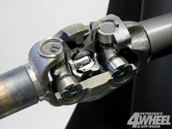
The CV joint assembly consists of two universal joints unified by a small ball and socket that pivots at the center of the joint. Using two joints allows one to rotate in a fixed position on the flange or yoke, while the other can spin in harmony as the shaft cycles. The two joints cancel out each other's fast/slow rotations, ending up in a constant velocity configuration. Sealed in a bed of grease and needle bearings, this ball joint is what allows the shaft to change degree without binding. Overextending the driveshaft, a lack of grease, and extreme angles are all quick ways to damage and shorten the lifespan of the CV joint.
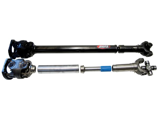
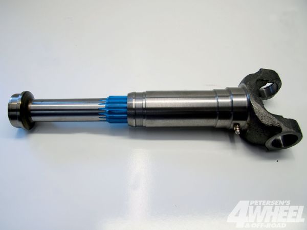
The Slip
As your suspension cycles, it causes the driveline to change length. To compensate for this, a slip joint is incorporated into the design of the shaft. The general rule is you want about 11/2 inches of slip showing at ride height. This can vary by application. It's best to consult with a driveline expert to be certain that your shaft has the proper amount of plunge.
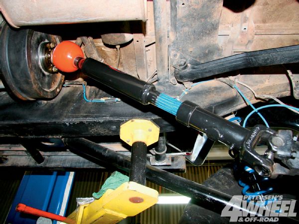
Spy Shots Of The Future
Extreme driveshaft angles can destroy the best of shafts. When mixed with long-travel suspension applications and short wheelbases, the degrees can reach into the 40s. We snapped this quick spy shot of a top-secret shaft experiment that JE Reel is working on. Capable of 45 degrees of operating angle, this new driveline just might be the future solution for people with high-angle needs. Stay tuned for a future issue where we take a closer look at this cutting-edge setup.