How many times have you found yourself suddenly confronted by a speed limit sign, then in a panic you look at the bouncing speedometer pointer and immediately start doing math in your head. "Let's see, this thing's off 12 percent, so multiply 75 by…" Unfortunately about the time you finish your calculations the rearview mirror is full of flashing lights and you vow to calibrate that speedometer once and for all. Thanks to Classic Instruments and the new Zeus technology, exact calibration and rock-steady speedometer readings can be yours.
Speedometers fall into two general categories, mechanical and electronic. Mechanical speedometers are normally driven off the transmission or driveshaft by a cable. That cable spins a magnet inside what is called a speed cup, which has the indicator needle attached. Basically a magnetic attraction occurs between the two and the faster the magnet is spun by the cable the farther the needle moves against the tension of a spring that returns the indicator to 0 when the vehicle stops.
In most cases mechanical speedometers are calibrated for the cable turning a given number of revolutions per mile, 940, 960, 1,000, or 1,020, depending on the make, but a variety of factors come into play that can impact accuracy. Change the rear gear ratio or the diameter of the drive tires and the relationship is altered. Common methods of compensating are changing the speedometer drive gear, installing a ratio box, or doing math in your head every time you see a speed limit sign.
Electronic speedometers have become popular for a variety of reasons, including ease of installation and calibration. Electronic speedometers receive a signal from either a pulse generator or a vehicle speed sensor—the greater the number of signals per driveshaft revolution the higher the speedometer reads and the greater number of miles shown on the odometer. Generally aftermarket speedometers use a pulse generator that sends out what is called a square wave electrical signal, essentially these are on and off switches that produces an electrical pulse. OEMs often use Vehicle Speed Sensors, which produce a sine wave, or a varying electrical pulse. This type of electrical signal is used in contemporary cars for everything from the speedometer to controlling variable assist power steering and antilock brakes.
Calibrating aftermarket electronic speedometers is usually a simple operation, when a specific speed or distance is reached a button is pushed or DIP switches on the back of the case are adjusted to correct an erroneous reading. Although the calibration procedures are simple enough, they aren't without drawbacks. In some cases the calibration button is on the face of the instrument and is less than attractive and adjusting those little DIP switches may require you to stand on your head under the dashboard. But the real issue with electronic speedometers can come from the electrical signal it receives or, in the case of radio interference, the unwanted signals it receives. If you've ever heard a buzzing from your car's radio when revving the engine, that's radio interference. It may come from spark plug wires, the alternator, or even a turn signal flasher and those stray signals can interfere with the operation of an electronic speedometer. To prevent problems keep the wires leading to the speedometer well away from other conductors.
More than a pretty face, behind the numbers is Classic Instruments' new Zeus technology. The patent-pending software eliminates all the shortcomings of electronic speedometers.
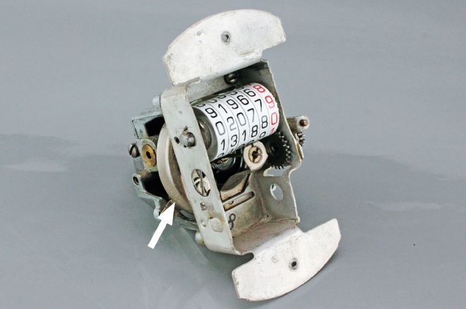
Cable-driven speedometers are becoming a thing of the past. The speed cup is the round piece behind the framework. The pointer attaches to the tiny shaft below the odometer.
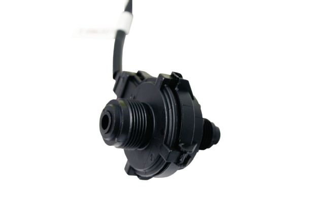
Mechanical speedometers, pulse generators, and some vehicle speed sensors are driven off a gear on the transmission's output shaft.
Inside the pulse generator are eight magnets and an armature spun by a gear on the output shaft.
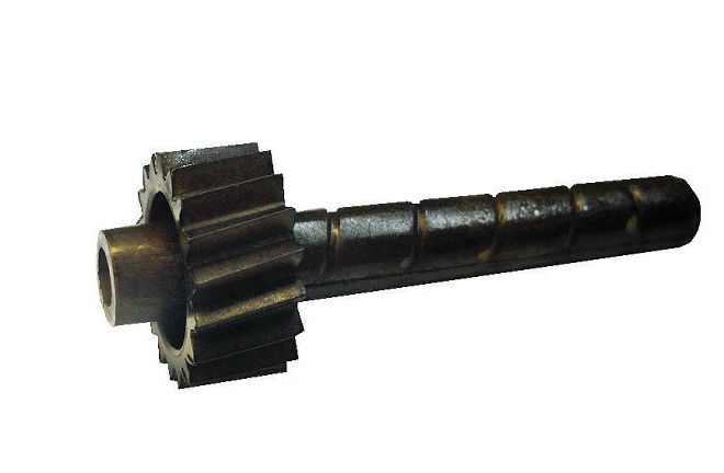
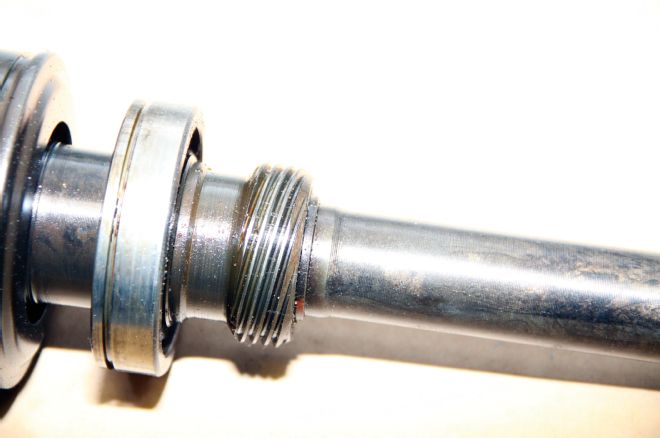
Calibrating a mechanical speedometer requires changing the driven gear in the transmission—in some cases close to right is all you can get due to gear availability.
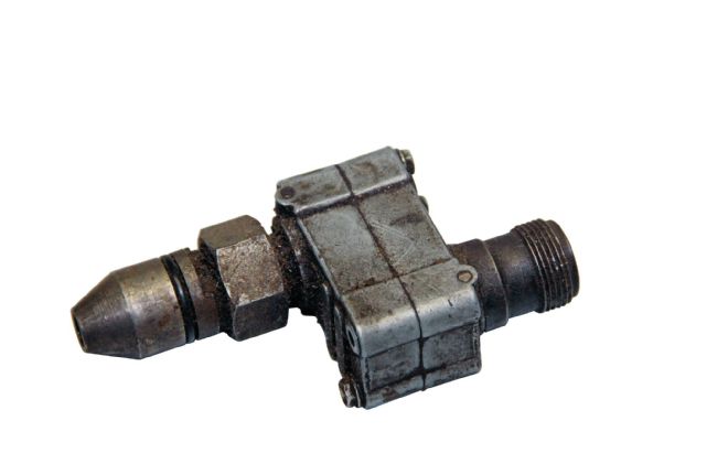
Another option for mechanical speedometers is a ratio adapter. It's necessary to know the amount of correction required as the ratio between input and output is fixed.
Electronic speedometers can also be sensitive to "dirty" electricity, which is most often caused by improper grounding not only of the instruments, but the rest of the electrical system as well. The chassis, engine, and body (as well as the instruments) should have clean, bare metal grounds leading to the battery. In addition the origin of electrical power for the speedometer should be an individual feed so the supply voltage doesn't vary.
While electronic speedometers have become standard issue in street rods, John McLeod and the team at Classic Instruments felt there was room for improvement, their efforts to achieve that goal resulted in Zeus Speedometer Technology (ZST). So advanced, it's covered by four pending patents.
Classic Instruments' ZST is a real game changer; it makes calibrating a sophisticated speedometer simple. This cutting age instrument operating software accepts any known speed signals (pulse generator, VSS-Vehicle Speed Sensor, ECM-Engine Control Module, or GPS-Global Positioning System) with no additional interface necessary between the sending unit and speedometer. Coupled with the ability to filter out radio interference the result is unparalleled accuracy and a steady, bounce-free pointer. But while all that is impressive stuff, possibly the best feature of all is that ZST speedometers can be instantaneously calibrated by driving 30 mph and simply pushing a button. The need for detailed calibration procedures, dip switch adjustments, or driving a marked mile has all been eliminated.
While ZST technology is revolutionary, it's not limited to speedometers. Classic Instruments has incorporated the same innovative software into tachometers to ensure smooth pointer operation in fluctuating signal conditions. It also allows calibration for 1- to 12-cylinder engines and there is an optional integrated shift light.
With ZST up and running the Classic Instruments crew decided the next step was to package the software in a way it could be used for other applications and the SN47Z was created. A standalone box, the SN47Z has all the advantages of ZST technology providing the same means of calibrating any electronic speedometer with any speed sensor, eliminating radio interference, and ensuring pointer stability. The SN47Z can also be used to drive electronic tachometers with the same advantages.
Classic Instruments offers an amazing array of instrumentation; you can check them out on their website or in their catalog. And if you want something of your own design, they're capable of creating just about anything you can imagine and include Zeus technology too.

FAQs from Classic Instruments
Common Speedometer Problems:
Speedometer pointer is erratic and gets worse the faster the vehicle goes.
Cause: The link between the pulse signal generator and the transmission's speedometer cable driven gear is slipping.
Solutions: The driven gear may be worn out. Replace the driven gear.
The pulse signal generator's shaft is not going far enough into the driven gear and is still in the tapered portion of the gear. Add a short piece of 1/8-inch-diameter shrink tube to the tip of the pulse signal generator's shaft to make it a little larger. (This will make the connection to the driven gear tighter, even in the tapered portion of the gear.) Another option is to run the signal from the pulse signal generator through the SN74Z; it will average the signal and output a stable frequency for the speedometer.
Speedometer acts like a tachometer, even when the vehicle is not moving.
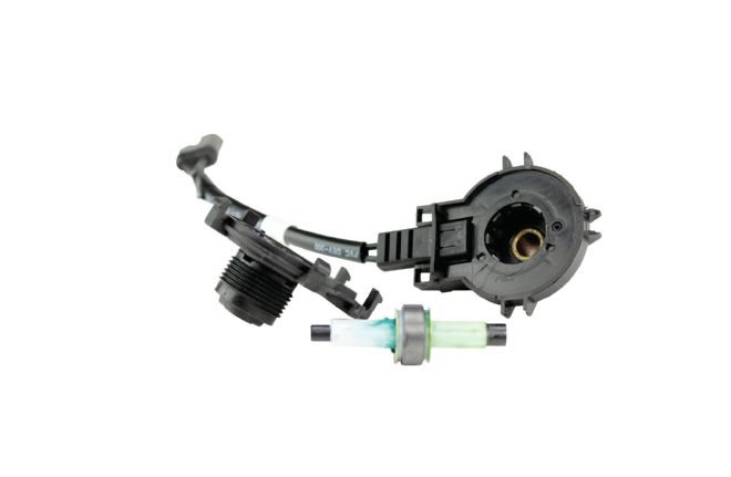
This is a pulse generator, the two-wire versions generate eight pulses per driveshaft revolution.
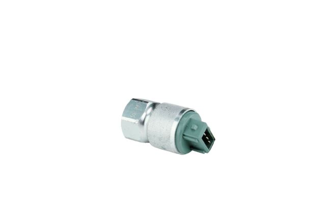
This is a three-wire, powered, pulse generator; it produces 16 pulses per driveshaft revolution.
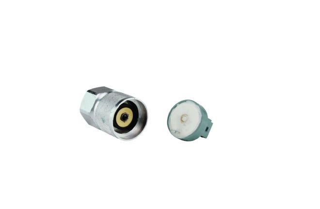
Inside is a ring with 16 magnets that spins adjacent to a pickup (the little protrusion from the piece on the right).
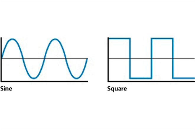
On the left is graphic representation how the voltage of a sine wave varies. By contrast a square wave is simply on and off.
This Classic Instrument body will house a speedometer, tach, voltmeter, and oil pressure gauges.
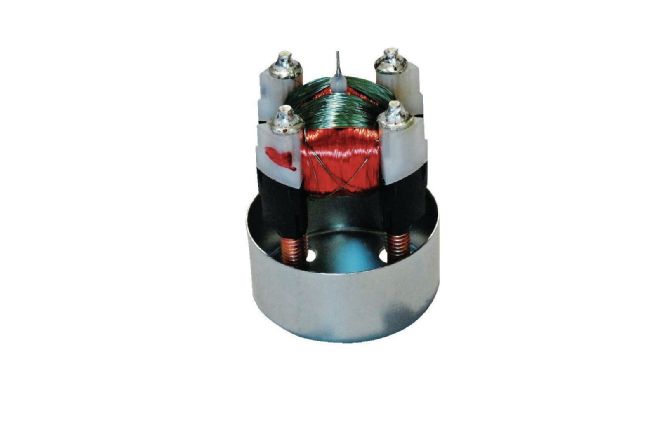
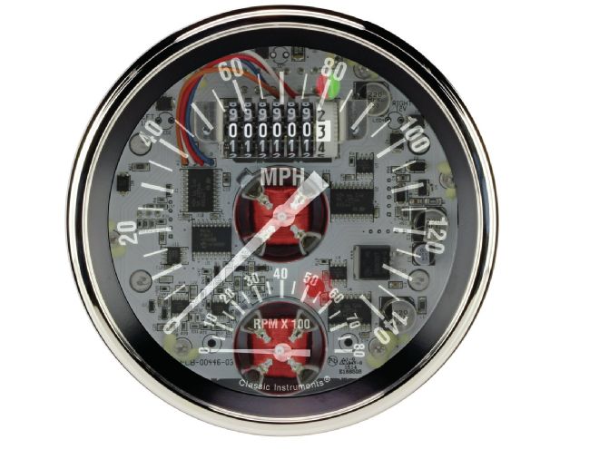
Classic Instruments uses what is called an air core movement—they provide extreme accuracy and greater indicator needle sweep. The Zeus technology is the software that operates the movements.
Cause: The speed signal is being affected by electrical interference.
Solutions: If using an OEM vehicle speed sensor, route the signal wires away from any high power wires. If this is not possible or doesn't solve the problem, use shielded cable (wires surrounded by foil with the foil being grounded by a bare "drain" wire) between the vehicle speed sensor on the transmission and the speedometer.
If using a three-wire (powered) pulse signal generator, use a 12V power line filter in line with the power to the pulse signal generator. Dirty power to the pulse signal generator will be transmitted on the signal wire to the speedometer and cause false signals.
Run the speed signal through a SN74Z, it provides filtered power for powered pulse signal generators and has active signal noise canceling.
Speedometer reads way too fast or way too slow.
Cause: The speed signal is the wrong frequency for the speedometer.
Solution: Run the speed signal through a SN74Z, it will adjust the speed frequency through a calibration procedure and output a signal to match the (Classic Instruments) speedometer's default setting. Use the speedometer calibration chart (for Classic Instruments speedometers with dip switches in the back) or calibration button (for Classic Instruments speedometers without dip switches) to adjust the speed reading. If the speedometer reading is not within the calibration chart, a SN74Z will be needed.
Speedometer doesn't register any speed.
Cause: The speed signal is the wrong type for the speedometer (sine wave signal when the speedometer requires a square wave signal).
Solution: Run the speed signal through a SN74Z, it will convert a sine wave signal to a 12V square wave signal that is needed for some Classic Instruments speedometers.
Make sure you have a valid speed signal. Two-wire speed signals will produce an AC voltage that gets larger the faster the vehicle is moving. Three-wire (and one-wire) speed signals produce a DC voltage that remains constant when moving and changes to 0 (or battery voltage) when not moving. Use a multi-meter to measure the speed signal.
Make sure the speedometer has power. Classic instruments speedometer pointers move slightly off the black pointer stop when powered. If the pointer is resting against the pointer stop, the gauge most likely is not powered.
Speedometer is acting erratic or not at all.
Cause: The speedometer has a bad electrical connection to the vehicle power, ground, or speed signal. (We have found wire nuts, wires twisted together wrapped with electrical tape).
Solution: Make sure all connectors are crimped, soldered, and shrink-wrapped. Many times a wire is just crimped and while crimping only a few strands of the wire are contacting the connector (if any). Soldering the connection helps ensure the connection is good and stays good. Shrink-wrapping the connectors ensures the connector doesn't inadvertently short to another wire.
A bad ground connection (having resistance to ground) can cause the speedometer to not get full voltage. Classic Instruments speedometers require good power to operate accurately and respond quickly. The faster the speed reading, the higher the power draw is from the speedometer. A bad ground (or power) can cause the speedometer to not have the power requirements it needs to perform quickly or at high speeds.
Last but not least, we recommend all connections are crimped, soldered, and shrink-wrapped. Many problems are the result of bad or loose connections, over tightening connections, broken wires, and the worst offender of all, bad grounds.
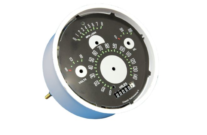
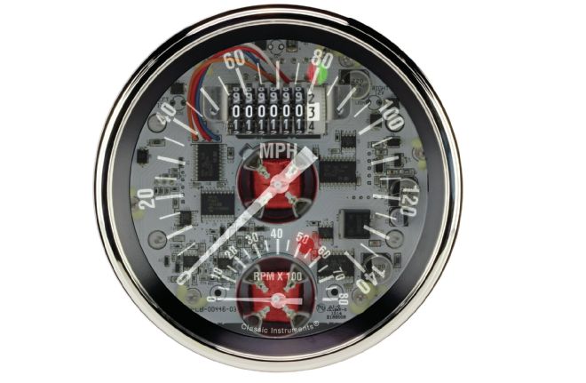
Here is the same instrument with the dial faces installed.
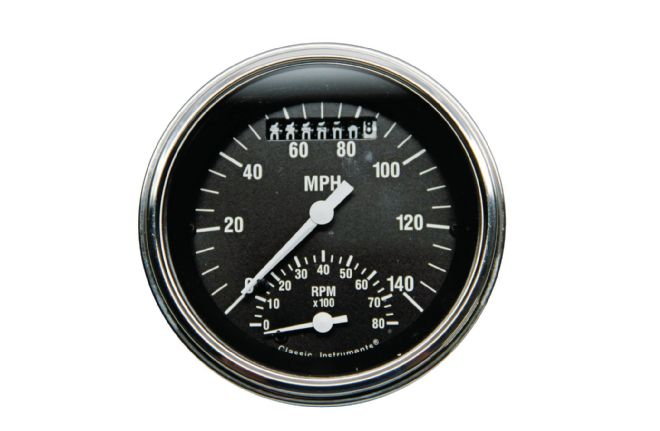
Another Classic Instruments ZST speedometer and tach combination. Clean and simple looking, the Zeus technology makes calibration simple and accurate with rock-solid needles.
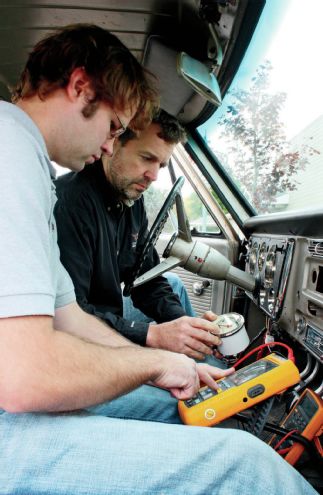
John McLeod (right), Devin Butterbrodt, and the Classic Instruments staff worked on perfecting ZST. Prototypes were tested in a variety of vehicles, including McLeod's C10 Chevy work truck.
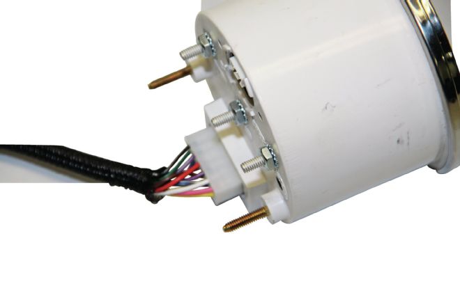
Installing a Zeus speedometer, speedometer/tach combo, or a quad configuration is a plug-and-play operation, as each has a dedicated wiring harness.
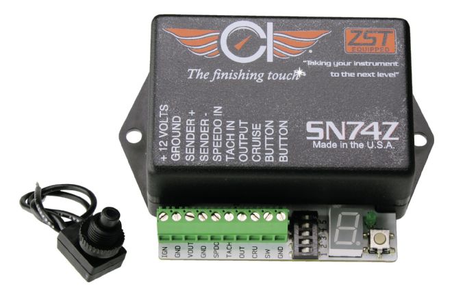
Classic Instruments' SN74Z can give regular speedometer and tachometers the advantages of Zeus technology. When in calibration mode the digital display lights up to indicate progress. Note the calibration button can be used and removed and there is an output for cruise control.