Time was when pretty much the only modification hot rodders made to their rear suspension was to add longer shackles to lower the rear on a transverse leaf-sprung Ford, or throw a set of lowering blocks between the axle and leaf springs on a Chevy or other car with parallel springs.
Things are a lot more specialized these days, and though lowering blocks and long shackles still have their place, the aftermarket now offers bolt-in and weld-in kits for everything from relatively simple upgraded leaf springs to complete IRS systems. Space restrictions mean we'll bump IRS systems for now and concentrate on live axles; or, more specifically, how that axle is located in the car. Spring rates and the benefits and disadvantages of coilovers versus leaf springs versus air springs is also another subject for another time. However, before we delve into the various types of rear suspension, there are a couple of important subjects we should first mention-scrub line and pinion angle.
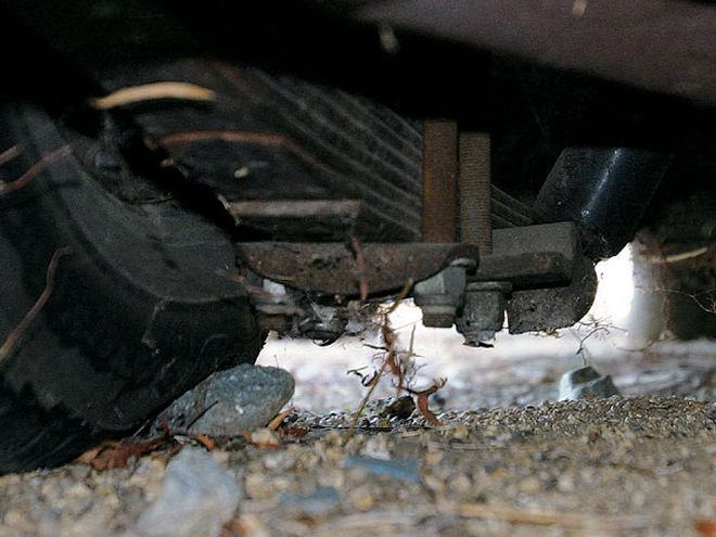 Imagine the consequences if this tire were to suffer a blowout at speed. And we don't mean the spider webs would blow away!
Scrub Line
Imagine your car-any car-sitting on the street without any tires. The wheels are still there, just without the rubber. Is anything touching the ground? Suspension parts, any brackets, exhaust system, fuel tank, transmission, or motor even? If so, they are below what is called the scrub line, and while you may not worry too much if those massive 6-inch lowering blocks meant the nuts on the U-bolts are now halfway down the sidewall of your rear tire, you'll be in for a nasty surprise if you get a flat on that tire at speed. Those U-bolts will make a nice gouge in the blacktop, and you'll be fighting to stay in control of the car ... if you're lucky. You'll more likely be in the ditch or facing oncoming traffic. Tall tires don't help either, but ensure no part of your undercarriage hangs down below an imaginary line drawn between the bottom of all four rims. In fact, an inch of clearance would be a good idea.
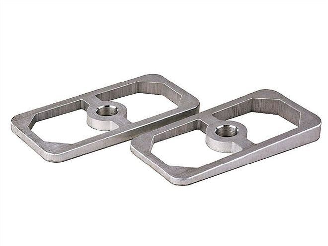 Speedway Motors, among other suppliers, sells these wedge shims to fit between the axle and lowering block to adjust the pinion angle if need be, though obviously setting the angle before welding the spring pads to the housing would be preferable.
Pinion Angle
We'll now open one of our favorite cans of worms, as whichever expert you consult will give you a different answer, depending on their particular automotive area of expertise. The pinion angle is the angle of the flange on the front of the rearend (the pinion) in relation to the angle of the driveshaft. That everyone will agree on. Well, most everyone anyway. It's how you measure that angle that causes disagreement.
But first you should understand why pinion angle is important. As power is applied, and the drivetrain is under load, the rearend tries to rotate around itself, meaning the pinion will rise. The goal is to create a straight line from the back of the crankshaft through the transmission, driveshaft, and the pinion of the differential, under load, so to achieve this under power, the pinion has to be angled slightly downward from the driveshaft when the vehicle is at rest. The awkward part is determining that angle. Different suspension setups will require different angles, though parallel leaf springs will require the most, owing to their tendency to "wind up." While all this may seem overly scientific, and the stuff of drag race chassis tuners, it is important on street cars, to eliminate driveline vibrations or ultimately component failure, and to ensure the longevity of your universal joints and bearings.
So what's the ultimate angle then? How long is a piece of string? Classic Performance Parts suggests mounting the engine and trans at a 4-degree-rearward angle, so the carburetor flange is parallel with the ground, then setting the pinion at 2-3 degrees upward from the ground, so that under load it will move upward, aligning it with the driveshaft and making the pinion angle 1-2 degrees. Currie Enterprises, who has manufactured more rearends than anyone else for the hot rod market, suggests a 1-3 degree angle between the transmission tailshaft and the driveshaft, and an equal angle between the driveshaft and the pinion. The centerline of the tailshaft and the centerline of the pinion shaft will be parallel, the angles mentioned above allowing the driveshaft to run between the two components using universal joints, which have a safe operating range of between 1 and 3 degrees. Obviously, zero degrees is the optimum, but U-joints work at their best when running through a slight angle, hence the 1-3 degree measurement.
If this is confusing, take a look at Inland Empire Driveline's Web site (www.iedls.com) under powertrain setup guides, where an excellent explanation with diagrams will clear up everything.
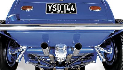
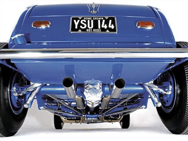
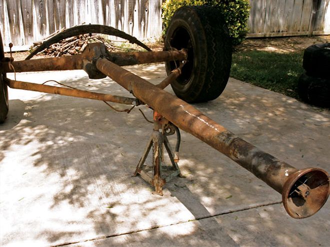 This '46-48 Ford rearend uses a transverse leaf spring and a torque tube for location. You can clearly see the solid driveshaft inside the half "ball" at the forward end of the torque tube, which is enclosed in a matching "cup" at the rear of the transmission.
Location, Location, Location
As with real estate, location is important, and by location we mean how your live axle is attached to the chassis. And there are plenty of options from which to choose: ladder bars, trailing arms, three-links, four-bars, four-links, triangulated four-links, and parallel leaf springs. Then there are torque tube-equipped axles. We'll deal with each application in turn.
Torque Tube / Transverse Leaf Springs
This style of suspension, the staple of early Fords up through 1948, is located using a cup-and-ball arrangement at the forward end of the torque tube, and on early Fords, apart from the spring and shock absorbers, that's the sole method of locating the axle. The spring limits any sideways movement, with wishbones (radius arms) triangulating the system, which bolt to each end of the axle casing, and to the torque tube toward the front.
If you're using an axle so equipped, you'll most likely be sticking with the stock system of a transverse spring. Even with such ancient technology, POSIES can supply new springs in varying rates.
 POSIES Super Slide Springs feature a domed pocket at the end of each spring leaf that houses a moly-nylon button.
Torque Tube / Parallel
Leaf SpringsOn an early Chevy, the torque tube also locates the axle at its forward end, but it uses parallel leaf springs instead of a transverse spring. The axle obviously travels in an arc about the front of the torque tube, as the axle and tube are a single assembly with no universal joint between them, which necessitates pivoting mounts between the axle and the springs. The clamp pins on the leaf springs are 1 inch ahead of the axle centerline, meaning it will sit too far forward in the wheel openings if you want to upgrade the axle and simply drop the new one on the original leaf. You have two options in this instance. POSIES offers new leaf springs with the clamp pin on the axle centerline that is designed to work with the stock perches, or Fatman Fabrications has a kit that lowers the car at the same time as mounting the axle in the correct place.
Parallel Leaf Springs
Parallel leaf springs are probably the most common type of rear suspension for '50s- and '60s-era cars. As the name implies, two leaf springs are mounted longitudinally in the car, one supporting each side of the axle. The front of the spring is mounted directly to bracketry on the chassis or unibody of the vehicle, while the rear of the spring is mounted on shackles that usually hang down from the chassis, but which can also be mounted so the spring eye is above the shackle bracket, as on early Chevys. Why the shackles? Because the rear spring mount has to be able to move, as the spring will increase slightly in length as the suspension compresses. Because the springs are mounted fore and aft of the axle, and in four places, there's very little sideways movement of the axle, though antisway bars may be fitted to reduce body roll.
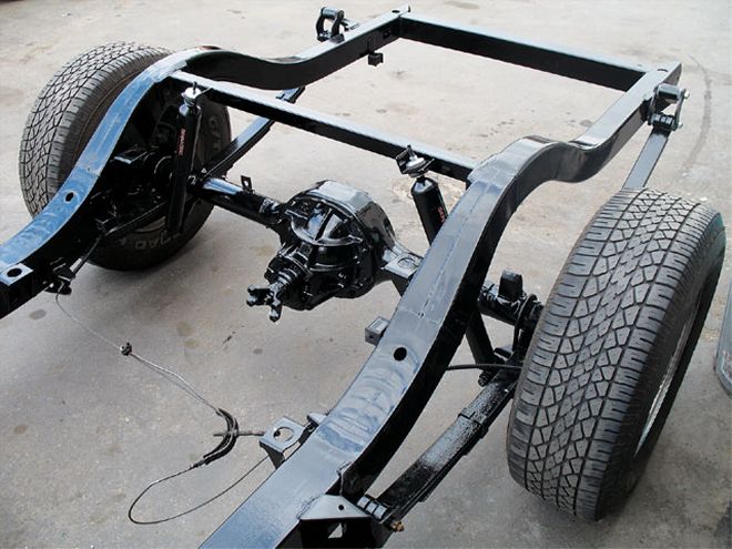 Parallel leaf springs, shown here on a '55 Chevy chassis with an upper shock crossmember added, were the main location system for rearends right up to the 1980s.
Ladder Bars
Mention ladder bars and nose-high gassers most likely spring to mind, but there are two types of ladder bars. Sure, the first type is usually seen on race or Pro Street cars and consists of a pair of triangulated bars that have a single mount at their front end and a pair of mounts at the axle end. In race-type cars, the ladder bars are usually around 30 inches long, and often are only adjustable at the front end. Some "double adjustable" ladder bars have more adjustability in their lower sections and can be used to fine-tune the pinion angle, which is often 1 or 2 degrees "nose down" in a race car application.
The second type of ladder bars, which is much longer, was developed by the street rod aftermarket and is offered by numerous manufacturers today such as SO-CAL Speed Shop-whose Pete Chapouris, along with Jim "Jake" Jacobs, pioneered such parts some 30 years ago as Pete & Jake's Hot Rod Parts. Rather than being mounted parallel, these ladder bars are mounted at the axle end as far outboard as possible, tapering in toward their forward ends, where they are mounted around 8 inches apart, usually either side of the driveshaft at the transmission crossmember. This type of ladder bar has no adjustment at the forward end, and clevis pins at the rear that offer very little adjustment. During setup, the brackets that weld to the axlehousing should not be fully welded until the pinion angle has been set. The triangulated setup allows similar suspension movement to the early Ford arrangement.
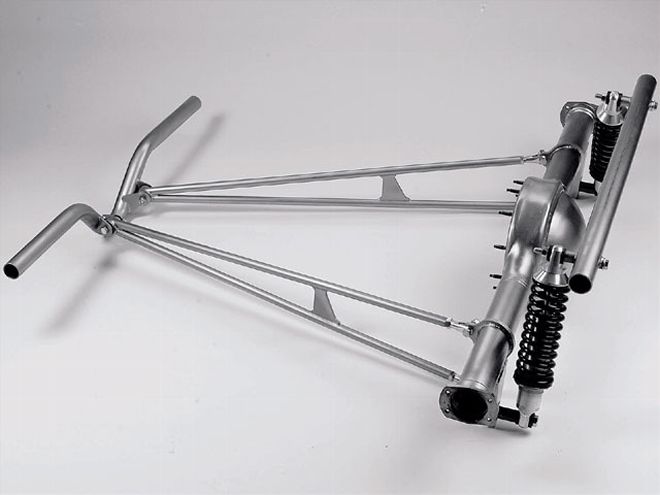
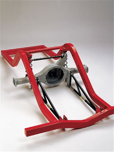 This ladder bar-suspended rear clip is part of a very comprehensive product line from Art Morrison Enterprises.
Ladder bars are a simple, easy-to-maintain style of axle location that fit easily under most floorpans, though the second type offers a smoother ride owing to the greater length of the bars. The first type is designed relatively short, as they provide a harder hit when a race car leaves the start line. Either type will require some form of lateral link to prevent sideways movement of the axle, though the second type can be used with a transverse spring, eliminating the need for this.
Trailing Arms
More familiarly seen on '60-72 Chevy pickup trucks as stock equipment, trailing arms have been used in the past on kustoms to good effect. They essentially work the same as ladder bars, with a single front mount, but instead of bolting to a vertical bracket on the axlehousing, two vertical bolts pass through the trailing arm and the axle pad. The length of the bars will provide an exceptionally smooth ride if the Chevy truck arms are used, or aftermarket versions such as those offered by Classic Performance Products. The factory trailing arms also offer a great lower mount for airbags, as the original coil spring mounts on them too.
Four-Links
A four-link offers the most adjustability of any rear axle location system, probably best suited for drag cars but worth mentioning here in case you're building a car with a performance bent. It allows fine-tuning for improved 60-foot times on the dragstrip. We can't see too many R&C readers using a four-link in their cars, so we won't dwell too long on it, but it is a form of axle location, and as such should be mentioned.
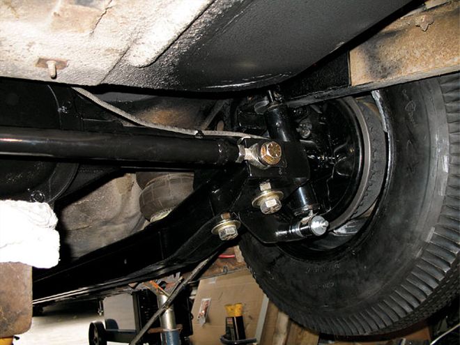 Stock Chevy C-10 pickup trailing arms are used to good effect on this shoebox Ford, providing a smooth ride and a lower mount for the airbags, while keeping everything tucked up above the scrub line.
Parallel Four-Bars
One of the most used systems in rodding today, and for good reason, the parallel four-bar takes up little, if any, interior room, works well, and is relatively maintenance-free. It's also inexpensive and fairly easy to install in most chassis.
As its name suggests, it comprises four bars, two per side, that run forward from the axle to brackets usually welded to the underside of the framerails. The upper and lower bars are parallel to each other when viewed from the side. They don't necessarily run parallel side to side; some kits feature angled urethane bushed joints at the end of the bars so the forward mounts are closer together than the mounts on the axle. This makes it easier to mount the forward brackets on most chassis and still mount the axle brackets reasonably far outboard. The system operates on a parallelogram principle, where the rearend always remains perpendicular to the ground, maintaining a constant pinion angle. With a Panhard rod providing lateral stability, the rearend is always in proper alignment.
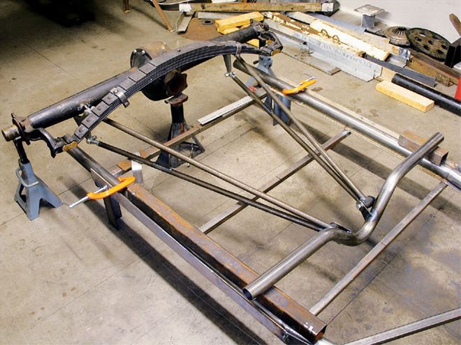
 Shown here suspended using coilover shocks, this whole assembly is available from SO-CAL Speed Shop, or the ladder bars can be purchased separately, with or without the axle brackets.
Three-Links
Again, maybe slightly outside the usual R&C field, a three-link will probably apply more to Pro Touring cars and the like. Coupled with an adjustable Watts linkage, it allows more rearend articulation without bind, and is perfect if you take your cornering seriously.
Triangulated Four-Bars
A growing number of hot rodders and custom owners are coming to appreciate good handling, realizing that bad road manners are not some-thing they have to put up with today. The triangulated four-bar rear suspension goes a long way in helping your old car perform like a modern one. This type of axle location has been around on production cars since the mid-'60s (GM A-bodies, for instance), but it's only relatively recently that people have moved on from simply replacing parallel leaf springs, for instance, with a more modern version of the same thing, to replacing them with an improved system.
The triangulated four-bar uses a pair of lower bars in much the same way as a regular parallel four-bar, but the upper pair of bars are located on the axlehousing near the center, either side of the pumpkin, and are angled outward toward the chassis 'rails at approximately 45 degrees. Mounting the upper bars at an angle eliminates the need for any form of lateral locator. Each of the four bars is adjustable to perfectly align the axle and adjust the pinion angle. Art Morrison Enterprises uses this system in its Tri-Five and Max G chassis, where a low center of gravity and great handling are required, and Air Ride Technologies reports it is the company's most popular system.
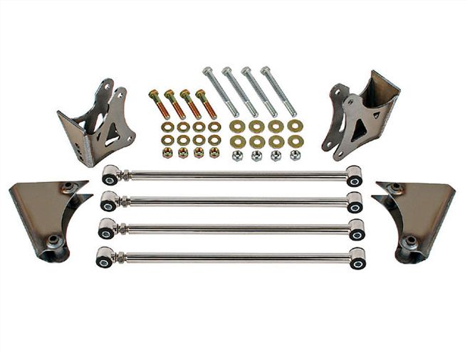 Speedway Motors offers this stainless steel four-bar kit for Model T, Model A, and '32-34 Fords.
Lateral Location
One thing we haven't mentioned yet is the various methods of lateral location; that is the ways to eliminate sideways movement of your rearend. The movement is limited anyway with a transverse leaf spring, and the triangulated four-bar eliminates sideways movement by its very design; but with the other forms of axle location discussed here, you will need some way to ensure your rearend remains central in the car. The most simple method is a Panhard rod, which is a bar running across the vehicle from the axle casing to the chassis. You could opt for a diagonal link if you have a four-link or four-bar rearend, or even a wishbone, though the latter is more of a race car option.
The Panhard rod shown on the Model A chassis on page 50 is bolted to welded brackets on the chassis and a bracket that bolts to the third member on the axle. The longer the Panhard rod, the smaller the arc it will travel in, and therefore limit sideways movement as the axle moves up or down. However, most hot rods have limited travel compared to OEM suspensions, and the movement is negligible.
Another option is to employ a Watts linkage, which is more complicated than the others but ensures your axle remains absolutely central at all times-something a Panhard rod can't do, as it has to move in an arc. You can see a Watts linkage in the Art Morrison three-link suspension photo on page 50. It consists of two bars, each attached to brackets on the chassis, their inner ends attached to a pivot on the rear of the differential. This pivot allows the axle to move up vertically, but not sideways.