What can you say about Corvette suspension that hasn't already been said? Even the early Corvette rears were popular for years. Now that they are all aluminum and quite sports car looking, they are popping up in all kinds of cars and trucks. They work well in the Tri-Five Chevy cars; you see them in all kinds of other applications.
Very swappable to start with, the stock front crossmember can even be used in some situations, including the stock monoleaf spring. The rear requires some brackets to be made and attaching the stock four-link arms can be tricky in some cases, but again, the stock rear monoleaf can usually be used. But if you use one of the available kits for the swap, you switch over to coilover shocks and their unlimited adjustability with spring rates and dampening. Coilovers will allow you to really dial in the corners.
The width of the C4 Corvette frontends, measuring hub face to hub face, depends on the year. The 1984-87s are 60.5 inches. The 1988-96s are 61.5 inches. The Fords and Chevys of the mid 1950s had a front width of 61 inches. So you can easily see the Vette will work quite well.
I call this measurement track width. It is the total width of the frontend, from hub to hub. Technically track width is measured by the manufacturers at the center of the tire to the center of the other tire. On a Corvette, this will throw off the actual measurement of 60 inches because the Vettes ran 9-inch-wide wheels with 7 or more inches of backspace so the actual "tire" centerline is in closer to the center of the vehicle and probably runs darn close to the upper and lower ball joint centerlines. That's why GM will list the front "track widths" at 57 and 59 inches. It depended on the wheel/tire combo the car was designed with.
For the classic pickup truck crowd, Donny McNiel's Flat Out Engineering of Anaheim, California, has had two real nice kits for the C4 Corvette suspension out for several years. The first kit is for the front suspension and includes the crossmember, needed brackets, C-sections for steering arm clearance, and a set of coilovers, the second is for the rear and includes all needed brackets and a new crossmember. I highly suggest you order their rack-and-pinion for this swap. The stock Corvette rack has a fitting that sticks straight up right where the oil pan wants to be. In the Corvette it doesn't matter because the engine is mounted behind the rack. Donny has had them modified so that the fitting points forward like the Mustang II and T-Bird racks.
Now mounting engines is not a problem. If you do decide to buy one of these kits and want the modified and rebuilt rack-and-pinion, and you do, contact Donny as he would love to have your stock rack as a core. The stock Corvette racks of these years aren't being made anymore so Donny has to find as many as he can to keep up with demand. He has found a local rebuilder that does the modification and rebuilds the racks for him. Donny is a great guy to deal with, has been in the street rod business for over 35 years, and he's no stranger to the high-quality classic truck owner's desire.
I have installed several of these front and rear kits from Flat Out Engineering over the years and they install easy and work great. The brackets are strong, well made, and look great when installed. The only tricky thing with the front kit is to pay very close attention to the instructions when lining the new crossmember up with the centerline. The Corvette spindle centerline is actually 5⁄16-inch behind the crossmember centerline. Split the width of the crossmember in half of its center, then make a mark 5⁄16-inch behind that mark and that is the line you line up with on the frame. Other than that, the install is very simple and straightforward.
I use all of the C-sections provided for the steering arms. It isn't so much that they need all that clearance when driving down the road, but it sure is nice to have the extra room when installing the rack. The rack has to be fed into each C-section then rolled into the mounts.
The Corvette front brakes are happy because the common master cylinder used in the aftermarket is the Corvette. If you go with a four-wheel disc system, then you will need the dual-diaphragm booster, not the single diaphragm that is commonly sold in a master cylinder booster combo. This truck is actually going to run big Wilwood disc brakes in the front and rear. The master cylinder dual diaphragm booster we will use is from Classic Performance Products. It comes with a new bracket to mount the booster that includes a pedal pivot so the stock brake pedal can be used. The booster kit comes with a metering block plumbed to the master cylinder, but you still need to install the inline residual check valves when plumbing your new brake system.
The C4 Corvette model ran from 1984 to 1996, back in the day of tuned port injection small-blocks and computer-controlled engine management in its infancy. I knew when I first saw these Vettes in 1984 that this suspension was going to become popular. As time went on that did prove true.
Follow along with the pictures as I install the front suspension, make some motor mounts, hook up the steering, and make the shifter work.
 1. Once the protective plastic is off these arms, this frontend really comes alive. Installing Corvette front suspension isn't for everybody, but those who have it love it. Sports car handling with awesome showy looks, it's the complete package next to a completely custom frontend.
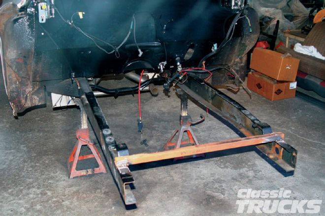
 2. It doesn't take long with two guys to get a truck apart. We have just removed the front fender assembly and we are going to turn the truck around to position it in the shop. Then we'll pull the motor and trans, front axle/spring assembly and trim, and grind the rails for the boxing plates.
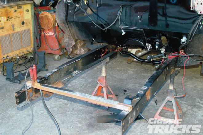 3. With the front axle and springs out of the way, I removed the stock front crossmember because it will interfere with the Corvette suspension. Boy, are those a job. Once it is out, the bottom flange of the framerails has a large piece that has to be trimmed off where the crossmember used to mount. I need the top and bottom rails 2 inches wide from the cab mounts forward so the flat boxing plates will fit properly. Chevys are the worst for having a lot to clean up before you can start installing. Fords just need a small trim here and there.
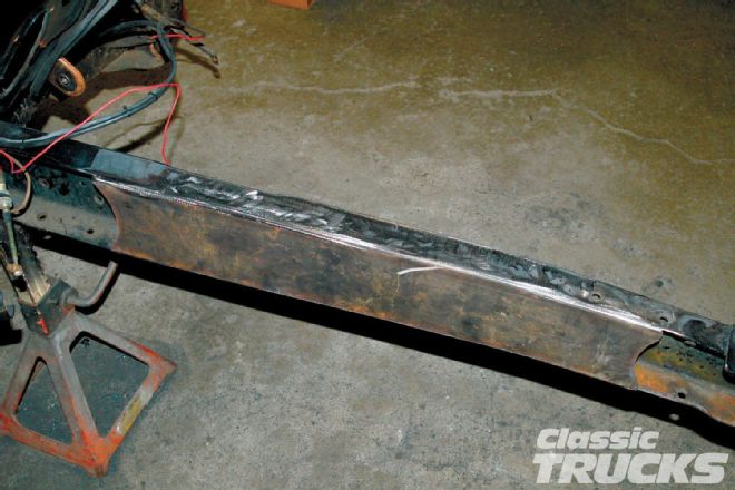
 4. Here we are all trimmed up and ground even. Chevys also have a lip on the top left rail for the steering box. I cut the curled part out and filled it with a piece of flat stock as the boxing plates went in.
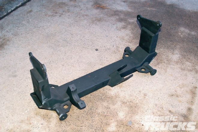 5. Flat Out Engineering's crossmember for the '80s C4 Corvette suspension. These crossmembers are top quality. The welds are ground smooth and the unit fits perfectly every time. I have installed several of these over the years in Fords and Chevys. You just can't beat Corvette suspension. OK, maybe you can. But Corvette gives you handling, ride, and snazzy looks if you have it all polished.
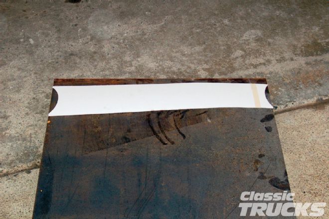 6. I wanted a little bit longer and slightly more styled boxing plates than came with the kit. I made up a cardstock template and transferred it to some 3⁄16-inch plate. A couple of swipes with the plasma cutter and some grinding and they were ready to install.
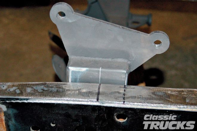
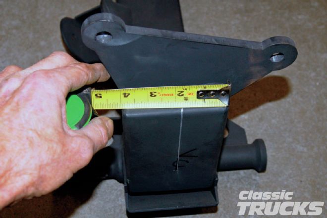 7. The true centerline of the Corvette front suspension is actually 5⁄16-inch behind the crossmember centerline. This is the line that will line up with the centerline on the framerail.
 8. If you don't finish weld and grind the boxing plates before installing the crossmember, some of the welds will not be easy to get to. I find you get a nicer-looking job in the end if you handle it first.
 9. Here we have the crossmember in place and lined up with a solid drawn centerline. The dotted centerline behind it is the true stock front axle centerline. When installing IFS kits in these old trucks, Ford and Chevy, you need to move the stock centerline forward 11⁄2 inches. This will center the front wheel in the wheel opening.
 10. Now that I have the crossmember tacked in place I want to double check it's placement with a wheel and tire in the fender opening. Chevys are tricky because of the shape of the wheel opening. If the wheel and tire are not just right, you see it and it doesn't look professional.
 11. We bolted the front fenders back on and I laid out some cuts for the A-arms to pass through. At the top corners of the cutout I used a step-drill bit to make 5⁄8-inch holes for the corners. Then cut out the straight parts with a cutoff wheel.
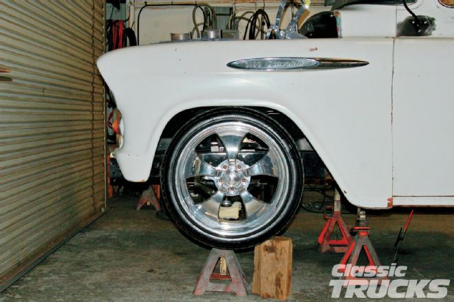 12. I then mocked a lower A-arm and spindle together with the upper arm. Then I bolted the wheel to the spindle hub. Standing back it looks pretty darn good. I would call the crossmember placement good. Here you can also see how if the crossmember was placed at the stock centerline, you would have had a tire up against the back edge of the fender opening. You see some running around like that. This is why.
 13. Now that I know that the crossmember is in the right spot, I move on to the C-sections for the rack-and-pinion steering arms.
 14. Flat Out supplies these with the kit. They may look tall, but you need to use the whole thing.
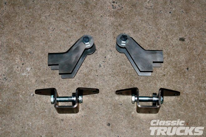 15. Also supplied in the kits are these upper and lower front shock mounts. The upper ones will weld onto the frame and crossmember and the lowers will bolt to the lower A-arm.
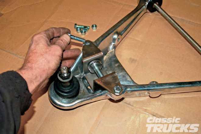 16. You need to bolt the lower mount to the shock then bolt the mount and shock to the A-arm. Drill out the holes on the A-arm to 3⁄8-inch and install the mount with the supplied bolts. As you can see the lower shock mount bolt is offset from its mounting holes and can be reversed. This will alter the ride height some.
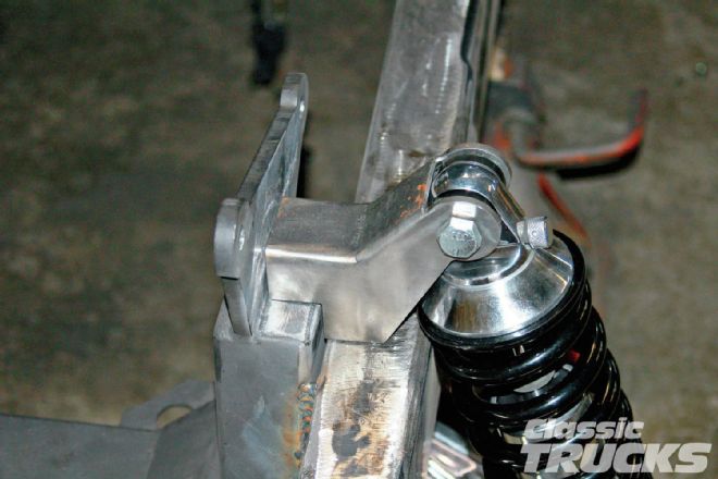 17. With the shock mocked in place the upper mount position is determined. It will just kinda fall into place and should line up pretty close with the crossmember centerline. You can also see that the top of the coil spring is hitting the framerail. For some reason this happens on the Chevy installs. The springs clear the framerails on the Ford installs. No problem, I have an easy fix.
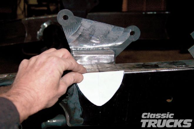 18. I'm going to make a cut in the framerail the shape of the cardstock template.
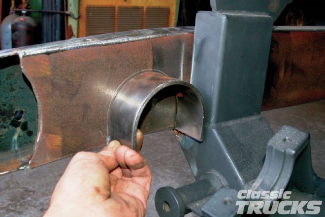
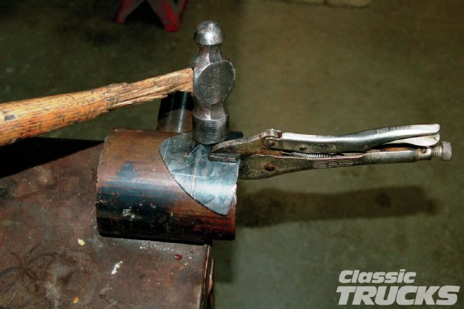 19. Then cut out a piece of 1⁄8-inch plate and shape it over a piece of tube. This will give a concave section where the spring can reside.
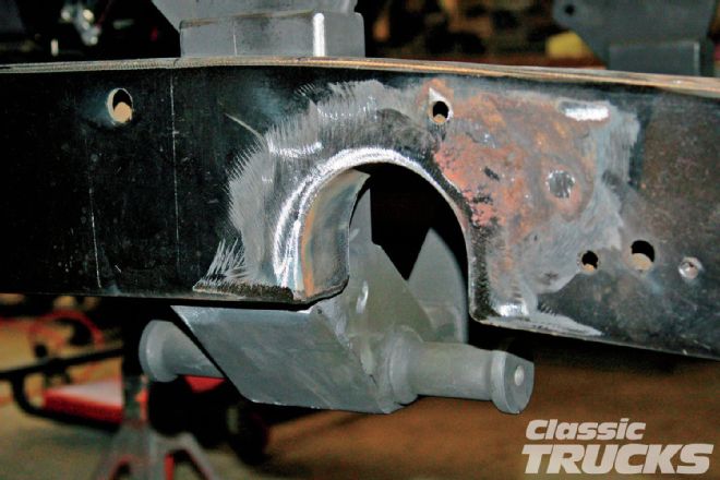
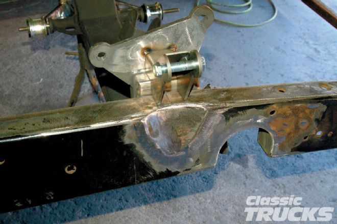 20. With the section cut out the new concave pieces were welded in and smoothed.
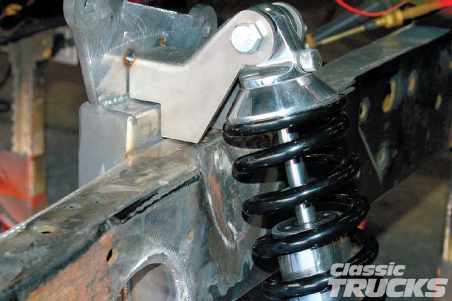 21. The springs now have plenty of clearance.
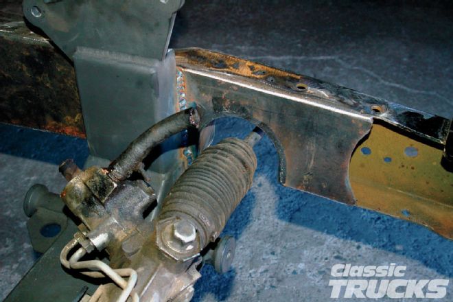 22. The rack is put in place to show how it fits the C-sections. Not only does using the whole supplied C-section give you plenty of room for the steering arm, you need that extra space when installing the rack itself.
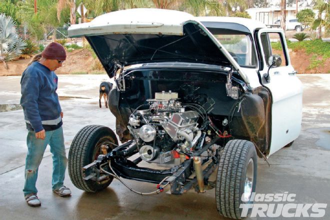
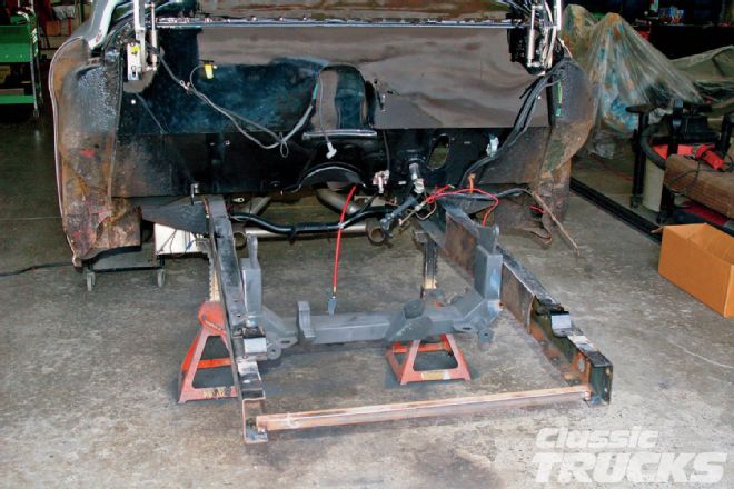
 23. Now that the suspension is in, it's time to mount the engine and trans. I get them positioned where I want them and mount the trans first.
 24. Then I come up, double check that the engine is still centered, and whip up some motor mounts.
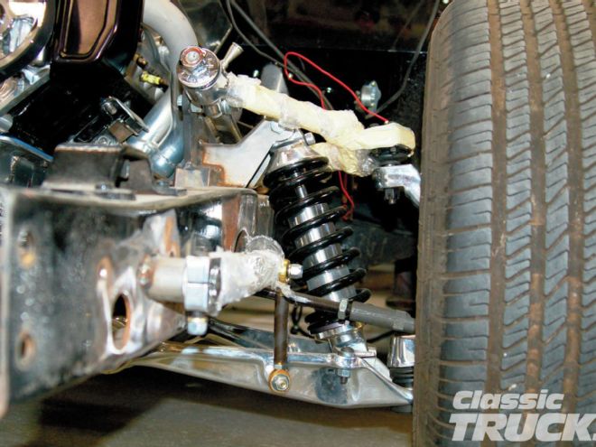
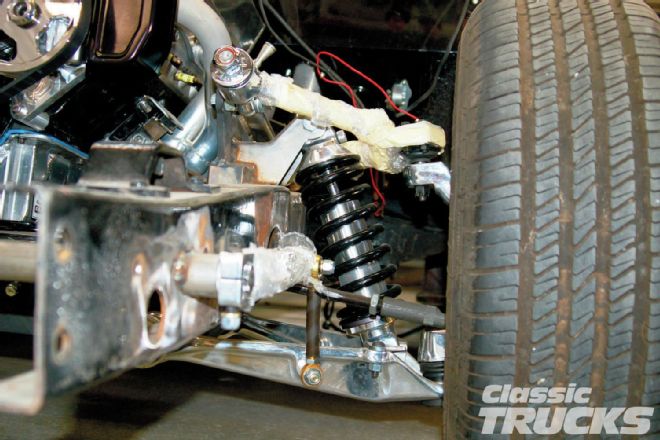
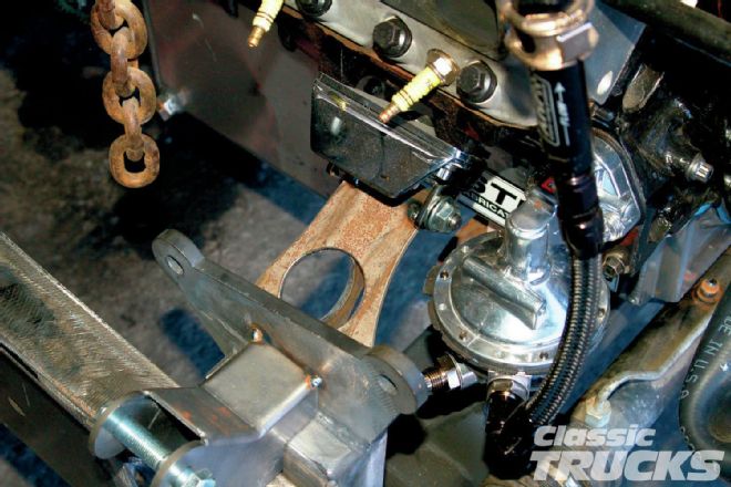
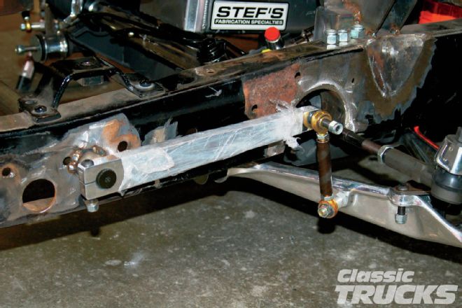
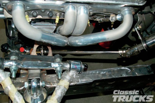
 25. This used to be a big problem with the Vette frontends. That fitting and hardline coming off the rack in the center of the picture used to stick straight up, right into the oil pan. Thank goodness Flat Out Engineering took care of that for us. They got together with Unisteer and they are making up these Vette racks with the fitting moved to the forward position. Now engine mounting is no problem.
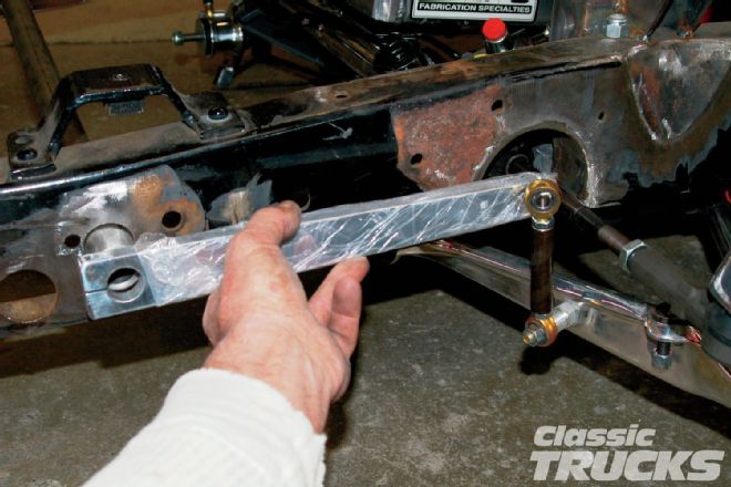 26. The stock Vette sway bar could probably have been used, but this is so much easier. This is the same sway bar kit from TCI that I used in the rear. I used the aluminum arm to figure where to hole saw the framerail for the sway bar tube. Now I am just double checking before I tack weld the tube in place.
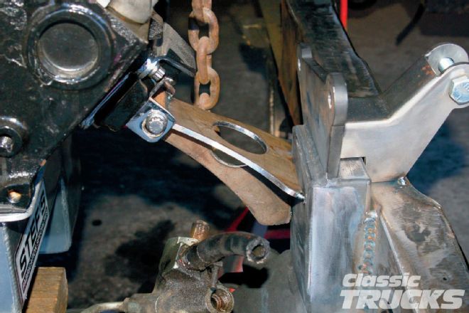
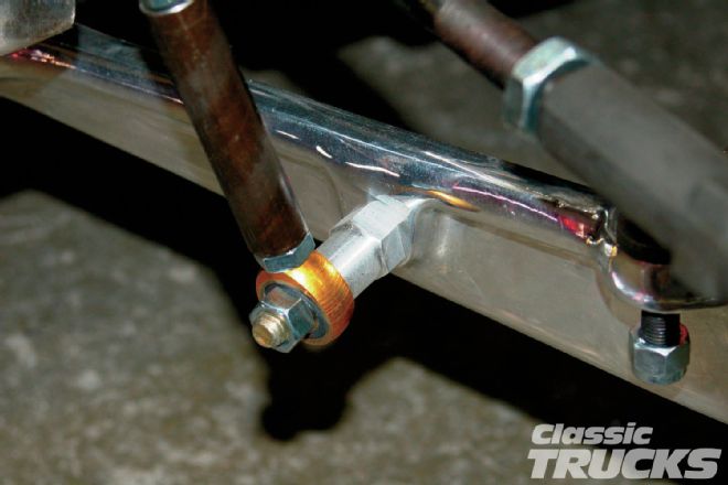 27. The hex aluminum is just a spacer for the Heim. It is helping give clearance at the steering arms. In final assembly the 3⁄8-inch mounting bolt will be upgraded to a Grade 8.
 28. With the tube positioned and tacked, the splined bar, arms, and Heim adjusters are all mocked into place.
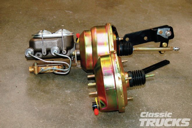 29. Classic Performance Products supplied the master cylinder and booster setup. The bracket bolts to the stock master cylinder mount and has a brake pedal pivot built in. Since the truck is going to be set up with four-wheel disc brakes, the booster needs to be a dual diaphragm, like the one the master cylinder is bolted to. The booster in the foreground is a single diaphragm booster. It works with the disc/drum setups.
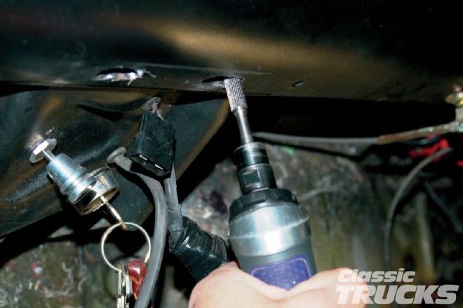 30. We are going to need some way to point this truck so a polished Flaming River steering column is being installed. In order to center the column on the point at the bottom of the gauge panel, I had to slot the holes with a carbide cutter.
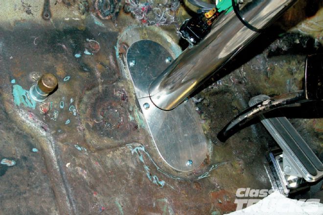 31. For a fill piece at the floor, I have a template I used to make this aluminum one. It is in two pieces and installed after the column is installed. I'll make a bracket to secure the bottom of the column to the fill piece.
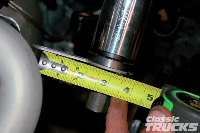
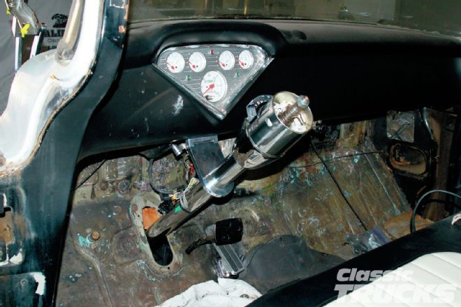 32. The column got mounted with a 41⁄2-inch drop, shown here. We felt it needed to be a bit shorter for leg clearance when you're exiting the truck. Brian is a big guy and we wanted him to be comfortable. We decided to change the drop to 31⁄2 inches.
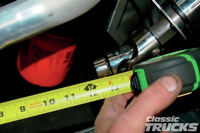 33. install the steering U-joints onto the end of the steering column and on the rack. Then measured for and cut a section of D-shaft. I install the shaft and tighten the Allen set screws to make a mark on the flat part of the shaft. Then remove the shaft and drill an indentation into the shaft with a 5⁄16-inch drill. This gives the set screw somewhere to lock into and secures the shaft a lot better.
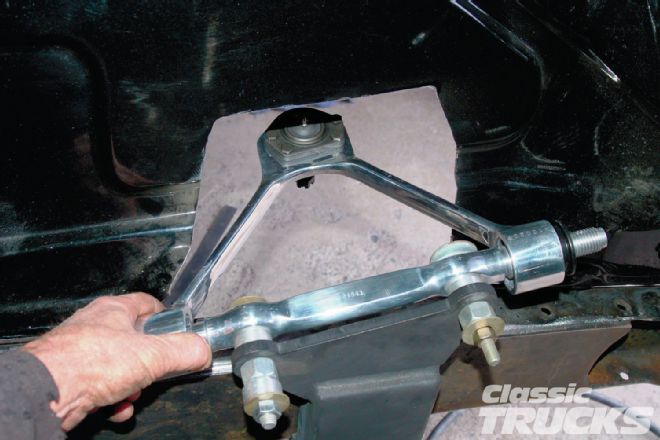
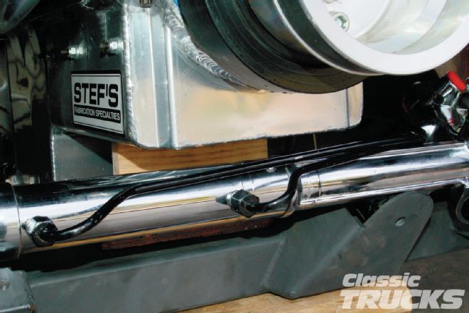
 34. Now the shaft is installed and the set screws and lock nuts tightened. I like aligning the U-joints so the set screws are pointing down out of sight when the steering is set straight. From this picture you can see I have a ton of clearance with the exhaust.
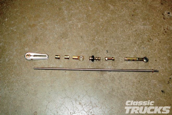 35. Here is a neat way to connect the GM trans to the steering column. This kit is from Classic Performance Products and works really well. Easy to install and positive shifting.
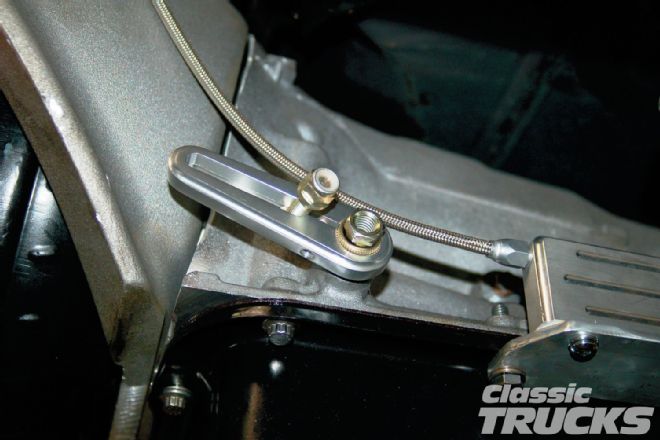 36. Simply install the splined collar onto the shift shaft of the trans, slide the aluminum arm on, and tighten and bolt the shaft to it via a Heim.
 37. Here's a little trick. If you keep the length of the arm at the trans the same length as the arm at the steering column, your shift indicator will line up a lot more often.
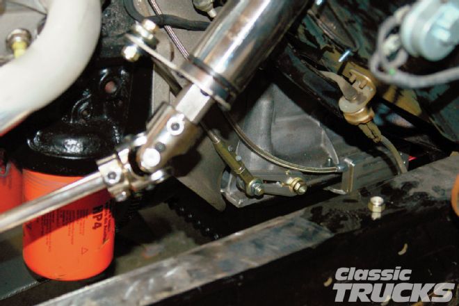 38. Here is a shot of the shift arm and shaft assembly all installed. This kit sure saved a lot of work. It looks great and is very positive feeling – another great product from Classic Performance.