In this issue we'll be picking up where we left off last issue. Now that we have the steering box and column mounted, it's time for the real fun part – making the bracket for the power steering pump. In the building of these trucks I really enjoy making the brackets and stuff required to mount all the various things that need mounting. Wiring them is another part I really enjoy.
The instructions from Mid Fifty said any commonly run pump will work fine. I chose an early '70s GM (Camaro) pump. It has a tapered shaft with a keyway and will accept all the different pulleys available. It's the same pump Bill's Brackets advises to use with his kits – inexpensive, good quality, and readily available. Don't forget to grab a reservoir cap for the pump as well since they usually don't come with the pump.
Another good choice would have been the GM X-car pump that is commonly used these days. You can use it with its stock plastic reservoir or go with a remote one mounted somewhere. Mounting the X-car pump is pretty easy too. You can either mount it solid using another accessory A/C compressor or alternator to adjust the belt, or fabricate a mount with an adjustment slot and have it adjust the belt.
For the GM pump I'm using, I basically start by holding it where I want it to go and make some quick reference measurements. Using those I can come up with a pattern and then make the bracket. In this case I am going to use the area where the fuel pump usually mounts. This truck had an electric one so this worked out well. Adjustment will be with a threaded ½-inch steel rod with 3⁄8-inch male Heim joints. The Heims are left- and right-hand thread so you can adjust the belt by turning the bar. The bar attaches to the pump and then to a small bracket at the water pump.
In this case, finding which groove in the pulley to use was easy. The engine already had two belts driving the alternator and only needed one. The outer belt won the honor of still powering the alternator and the inside belt is going to be used to drive the power steering. Installing the hoses was a snap also. I like to use a touch of antiseize on the flare part of the male fitting. Let a little get on the threads too. Then install the hose fitting and tighten. The antiseize will help the flare area seal. Trust me, it works. I always use it when working with aluminum or steel AN fittings.
My hoses fit fine without cutting them so I just made the connections at the pump and tightened everything up. Filled the reservoir with fluid and started her up to check for leaks and see how easy it turned.
It does have a power assisted feel to it and is a whole world better than the stock box. Lock to lock is just over four turns so it still steers like a truck in that aspect, not the two-and-a-half that a Mustang II is, but when driving it you definitely feel the improvement.
All in all, I think it's a great kit. Easy to install, as long as you don't run into clearance problems, and it looks great. It's all quality stuff that should work well until you finally decide to switch to IFS.
Swappers note: the compactness of the Toyota box and the way in which it mounts, it could easily (by fabricating any kind of mounting bracket) find its way into a lot of different applications – trucks being the most common. In fact, any type of front axle using a drag link to activate the steering might be able to use this box.
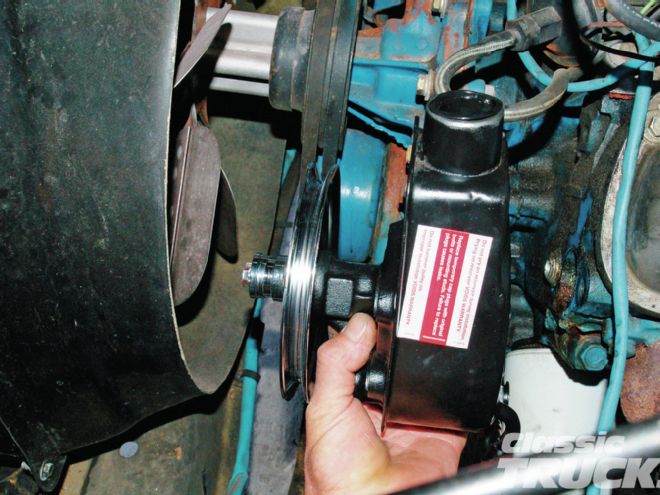
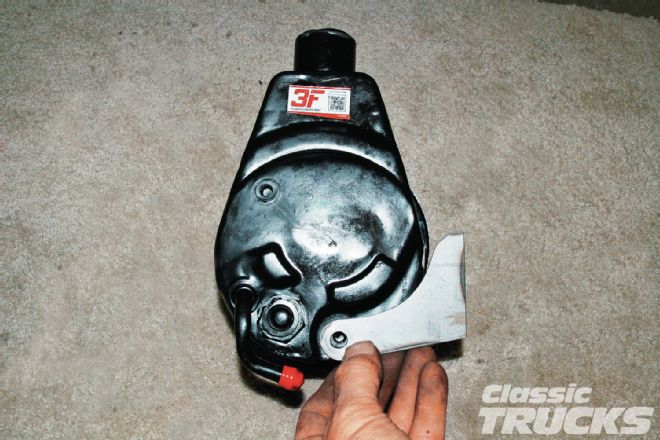
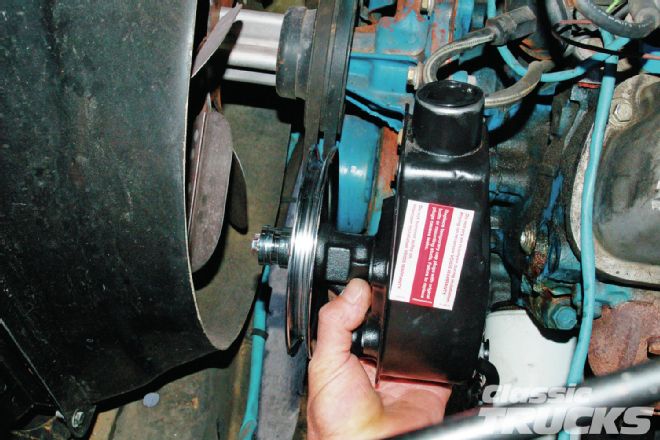 1. I'm going to use an early '70s GM power steering pump. They are readily available, cheap, and easy to mount. I have the whole driver side of the engine open, so obviously that's where it's going to go. I'm going to use the fuel pump boss to mount my lower bracket to. By holding the pump in place I can get some rough measurements to make the pattern to fabricate the bracket from.
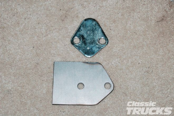 2. Using the block-off plate as a template, I made the mounting tab part first.
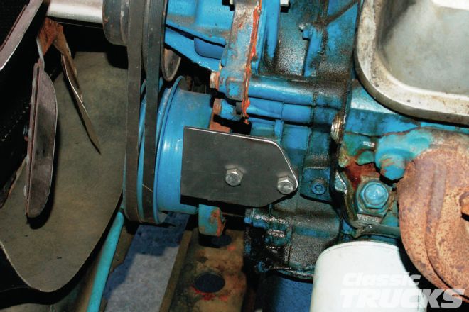 3. Bolting it to the block, I again hold the pump in place and get a better measurement for the next pieces of the mount, the two that will come out and catch the bottom bolts of the power steering pump. This will form the pivot of the adjustment.
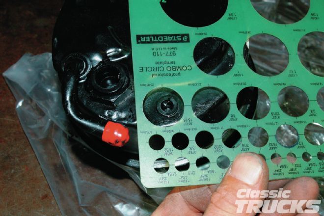 4. My circle template tells me that a 1-inch circle will be the right size for the end of the bracket. I'm using the usual front and rear 3⁄8-inch bolts that form the pivot of the pump for tightening the belt. The tabs will come off the pump and weld to the mounting tab I have bolted to the engine.
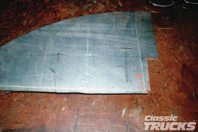 5. I draw my 1-inch circle and center punch for the 3⁄8-inch hole to be drilled. My eyeball measurements said I needed the bracket 21⁄4-inch long from the center of the 3⁄8-inch hole. I draw in that vertical line next. Then it's just a matter of drawing in a nice radius to connect the circle to the straight vertical line.
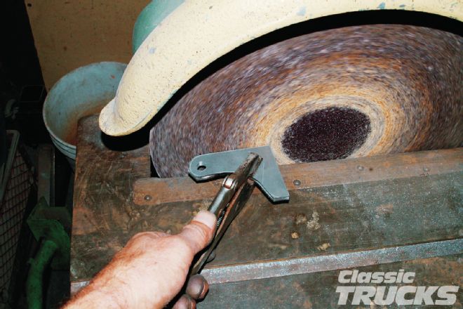 6. I cut them out on the bandsaw then dressed them up on the Apex grinder.
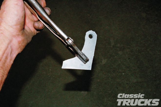 7. They both need to be the same shape so I have them clamped together with the Vise-Grips.
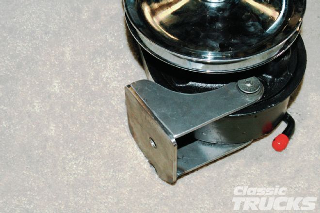
 8. A quick test fit on the pump and it looks like they're fitting pretty well.
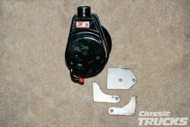 9. Here's what I have so far. The two tabs will weld to the mounting tab that will bolt to the fuel pump boss.
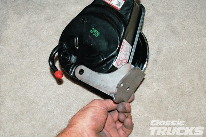 10. I tacked the rear tab on where I thought it should go and mounted the pump to it. Then back to the engine to check the fan belt alignment by bolting the bracket in place.
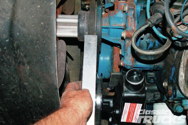 11. According to this measurement, I only missed by a 1⁄4 inch. Not bad. I took the bracket back off, broke the tack welds loose and moved the bracket 1⁄4 inch forward on the mounting tab. Another couple of tacks and bolted it back on to recheck. Seeing that it was just right, I removed the bracket and welded on the front tab and finish welded the back one. Once it cooled I bolted it all back in place to move on to the upper adjusting rod.
 12. Here the bracket pieces are mocked onto the pump to check the fit and tack weld the outer bracket in place. Notice I'm using countersunk bolts for the bracket to pump. The countersink will keep your holes lined up perfectly when tacking or welding.
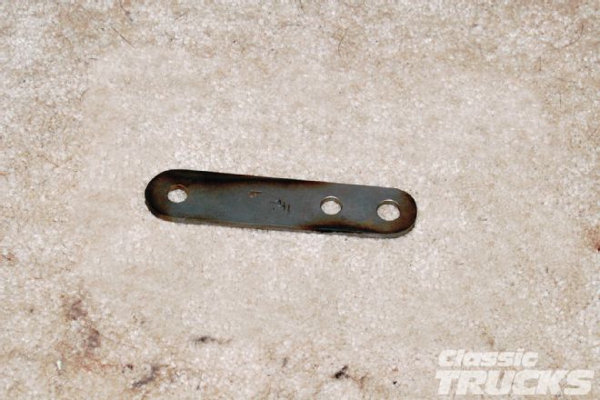
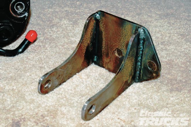 13. Here is the finished-welded bracket ready to be installed.
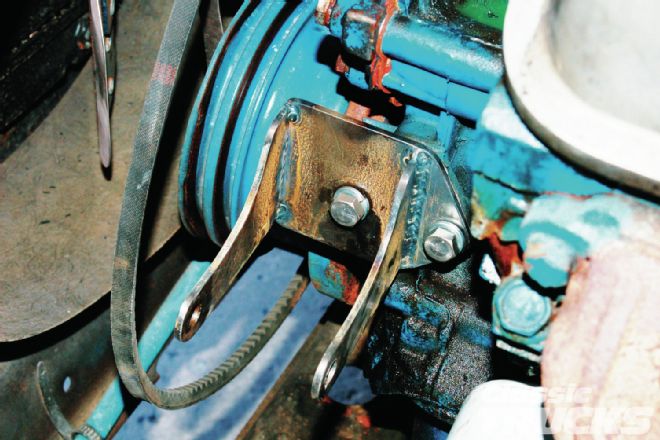
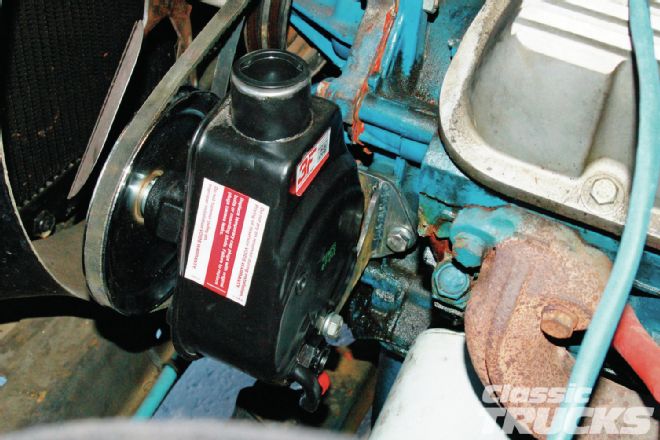 14. The bracket bolted to the fuel pump boss and the pump bolted to the bracket.
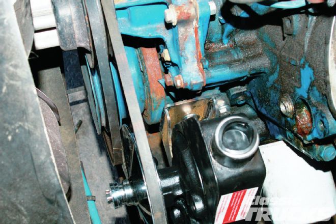 15. I can see my belt alignment is good and the bracket fits good as well.
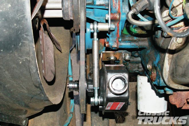
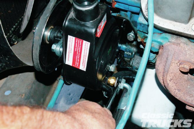
 16. I'm going to use a piece of 1⁄2-inch steel rod, drill, and tap it for 3⁄8-inch Heim joints and use it as my belt tensioner. Since the water pump bolts are all 5⁄16-inch, the upper Heim joint needed to mount to a small bracket mounted to the water pump with a 3⁄8-inch hole – nothing special, just a tab to bolt the Heim to.
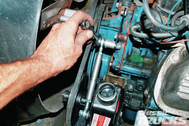 17. With the rod installed, I tried screwing it out to tighten the belt. It worked out pretty well too.
 18. The 1⁄2-inch rod is tapped for 3⁄8x24 left and right-hand Heim joints that allows you to screw it in and out for adjustment.
 19. Here's another view of how the bracket bolts to the fuel pump boss. The other two holes pick up the normal boltholes used on the pump as a pivot.
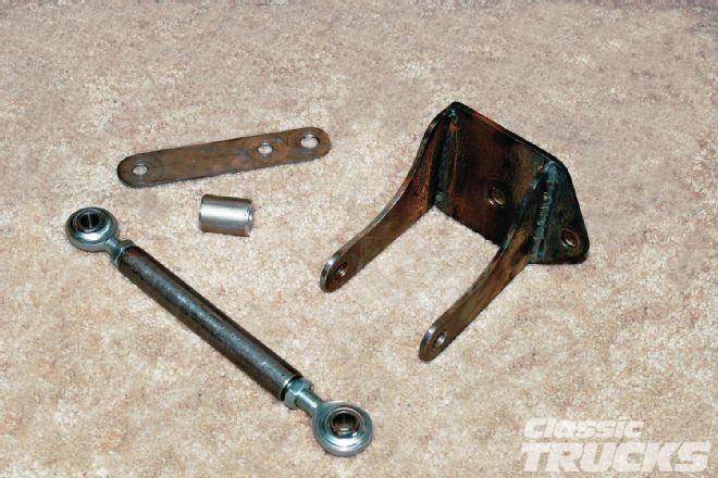 20. The brackets were made out of 1⁄8-inch plate and the spacer is a short piece of 5⁄8-inch aluminum rod drilled 3⁄8-inch for the bolt. The adjuster rod is 1⁄2-inch steel rod, but aluminum could also be used. The Heim joints were purchased at a local hardware supply store. A little bit of paint and the parts will be ready for final install.
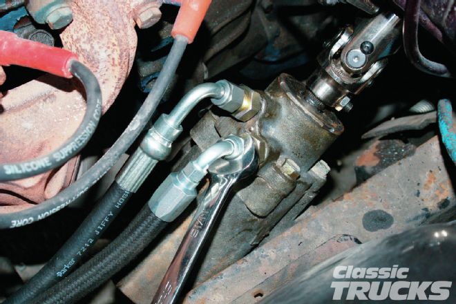 21. At this point all that was left was to install the hoses and fittings. The pressure side is the one next to the framerail and is always 16mm. The return side is 14mm on the 1979 and '80 boxes.
 22. These boxes have the straight splined input shafts – the return side on the 1980 to '85 boxes is 17mm and the input shaft is splined, but also has a groove machined in it for a lock bolt. By the way, Classic Performance Products can provide all the fittings you might need to complete the hose install.