Just like you wouldn't attach sturdy table legs to a flimsy tabletop, it makes no sense to bolt a state-of-the-art aftermarket suspension system to a floppy chassis. Unless a car's chassis is stiff enough to endure the immense cornering loads that modern g-Machines can produce, the countless R&D hours a bunch of smart engineers invested in improving suspension geometry, revising camber curves, increasing roll stiffness, and optimizing shock valving all go down the toilet in one expensive flush. With the groundbreaking aluminum front suspension and four-link rear suspension Detroit Speed and Engineering (DSE) recently launched for 1964-70 Ford Mustangs, it's hardly surprising that DSE also designed a set of matching subframe connectors.
To put the importance of a stiff structure into perspective, consider that the typical unibody chassis of the muscle car era was only designed to handle 300 or so gross horsepower on skinny bias-ply tires. In contrast, modern Pro Touring rides often crank out upward of 600 net horsepower, and stick it to the pavement with sticky R-compound tires exceeding 300mm in width. Putting that much power and grip through an unfortified unibody will twist it up like a wet noodle in no time, which is why subframe connectors are such essential pieces of hardware. By tying the front and rear subframes of a car together, they help a unibody chassis mimic the stiffness of a full-frame car.
While that might sound like a great deal, installing subframe connectors certainly has drawbacks as well. Running a long piece of round or rectangular tubing beneath the entire length of the floorpan can compromise ground clearance, and on g-Machines that already sit low to the pavement, that's a very bad thing. Likewise, unsightly bracing hanging down below the rocker panels flat-out looks ugly. Not surprisingly, DSE wasn't OK with this either. Never a company that cuts corners, DSE put forth the extra effort to design its Mustang subframe connectors the right way, not the easy way. In contrast to a more typical subframe connector setup that hangs way low, the DSE protrudes through the floorboard and into the cabin at the rear seat footwell area to maximize ground clearance. Part of what makes this possible is a custom DSE torque box that serves as an anchoring point for the rear of the subframe connectors. Although this arrangement does require a fair amount of cutting and welding, the payoff is a superclean install without any compromise in ground clearance. DSE installed one of its new subframe connector kits on its 1965 Mustang fastback project car, and we wanted to be the first to document the process.
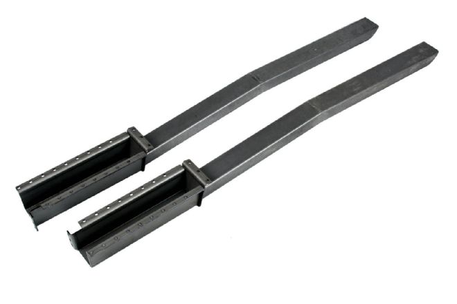 1. The DSE subframe connectors for 1964-68 Mustangs (PN 010105) are built from 1.5x2.5-inch rectangular steel tubing with .083-inch wall thickness. The kit includes reinforcement plates that wrap around the front subframes for additional strength. DSE also makes a kit for ’69-70 Mustangs (PN 010108). At $190, it’s a small price to pay for a substantial increase in torsional rigidity.
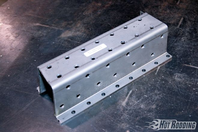
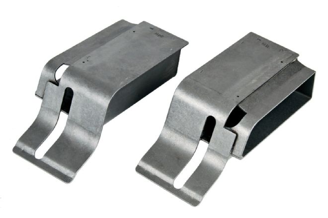 2. The rear of the DSE subframe connectors attach to DSE torque boxes that are included with the QuadraLink rear suspension system. The torque boxes are available separately (PN 010107) for Mustangs that aren’t equipped with the QuadraLink suspension.
 3. Using the template supplied with the DSE kit, mark the cut lines where the subframe connector rails will slide into the cabin with a scribe tool. Use a straightedge to ensure that the template sits squarely on the front subframe rail. Next, center-punch the corners of the cutout area and connect the marks with a scribe tool and straightedge.
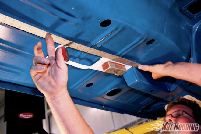
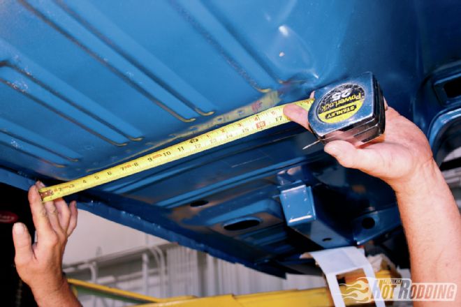 4. The subframe connectors must slide through both the floorpan and seat riser. Measuring and taking note of the distance from the corners of the floorpan cutout to the pinch rails will help locate the cutout area on the seat riser once work resumes inside the car.
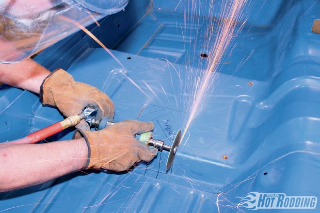
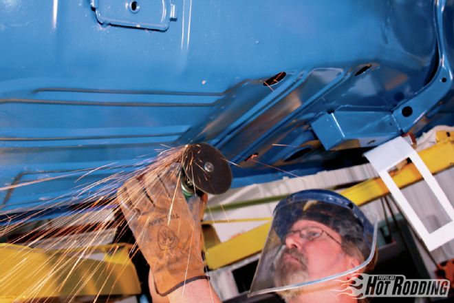 5. Cut the floorpan along the lines using a cutoff wheel. To prepare the floor for welding, remove paint from around the edges of the cutout area using a grinder. Strip the front subframe down to bare metal as well.
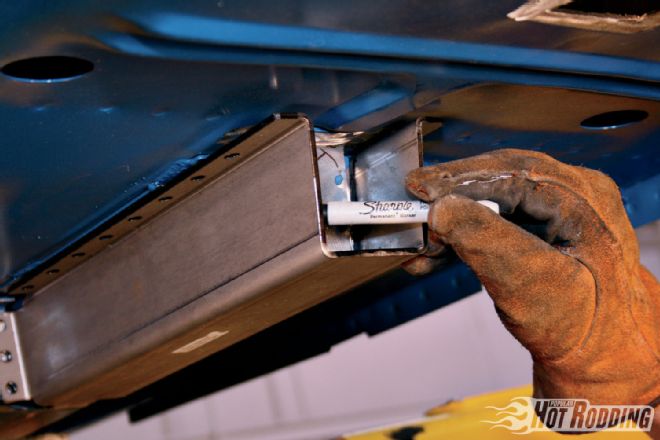 6. Since the factory front subframe was never designed to handle the increased loads of a modern Pro Touring machine, the DSE kit includes beefy reinforcement plates that encase the factory rails. The plate is designed to fit a broad range of model years, so it may be necessary to trim it down. Test-fit the plate into position, then mark cut lines of any excess material that must be removed.
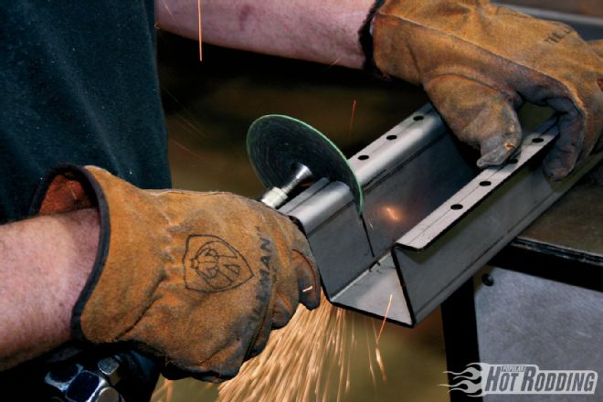 7. For best results, trim down the reinforcement plate on a workbench using a cutoff wheel. Start cutting at the outer edges, then work inward.
 8. To prep the reinforcement plates for plug-welding, drill ⅜-inch holes spaced 1-inch apart along the bottom and sides of the plate. This will net 12-14 plug weld holes on each flat section of the plate. Deburr any sharp edges, then spray the plate down with weld-thru primer to prevent rust.
 9. Tap the reinforcement plate firmly over the front subframe with a mallet, making sure that it sits flush against the framerail and floorpan. Next, plug-weld the plate into place.
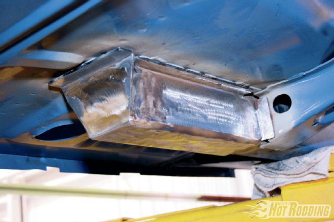 10. The reinforcement plate also includes a closeout panel that must be plug-welded to the rear of the front subframe rail. After doing so, grind all the plug welds along the plate down to a smooth finish.
 11. Using the measurements taken from beneath the car, measure from the edge of the floorpan to the base of the seat riser and draw a vertical line. On DSE’s Mustang, this distance measured 11.125 inches and established the centerline location of the subframe connectors. Line the supplied seat riser cutout template up to the vertical line, and trace the cutout area. Next, cut out the seat riser section with a cutoff wheel.
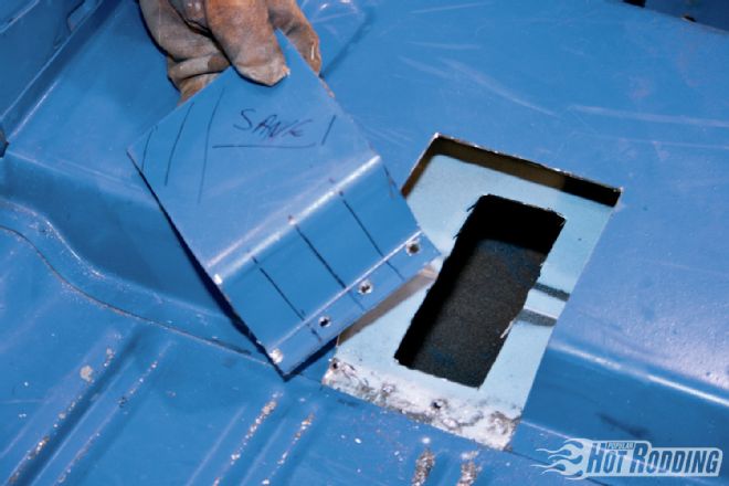 12. The seat riser cutout will be reused, so be sure to save it. With both the floorpan and seat riser cut, test-fit the subframe connector by sliding it into the cabin from beneath the car. Trace an outline of the subframe connectors onto the interior floorpan, then drill out holes into the floor in preparation for plug-welding.
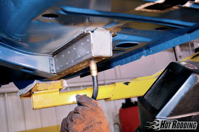
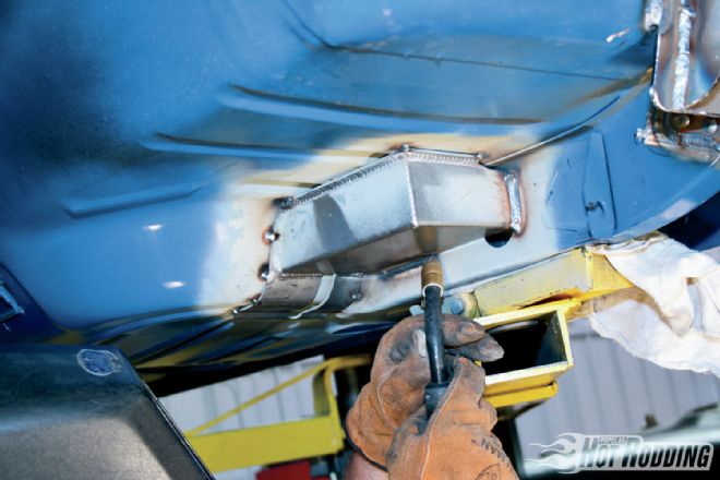
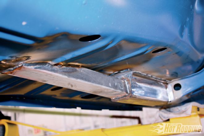 13. From inside the car, press the rear of the subframe connector firmly to the floor and tack-weld it into position. After moving back beneath the car, stitch-weld the front of the subframe connector to the subframe reinforcement plate and the floor.
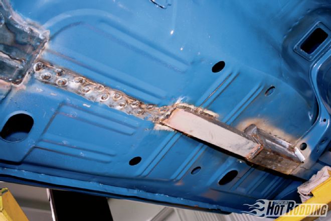 14. The rear section of the subframe connector must be plug-welded to the floor from beneath the car. Lay down two rows of welds in an alternating pattern, then grind them to a smooth finish.
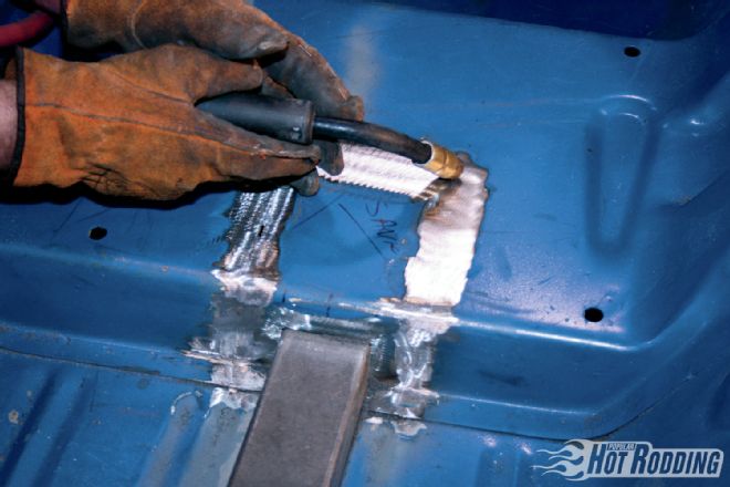
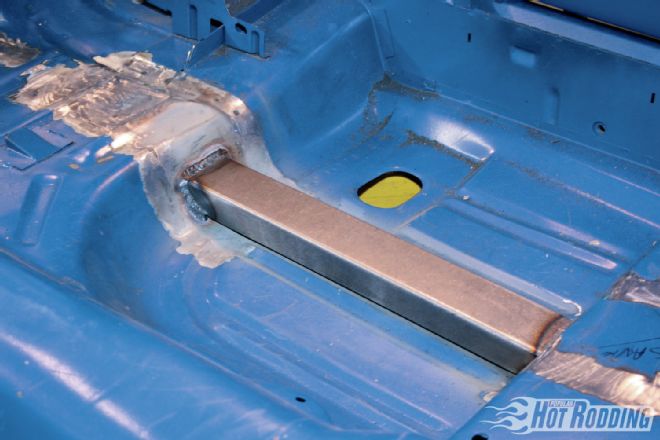 15. From inside the car, stitch-weld the rear of the subframe connector to the floorpan. This attachment area is reinforced by a DSE torque box located on the opposite side of the floorpan.
 16. The DSE torque box reinforces the floorpan against the rear framerail, and was already installed as part of the QuadraLink rear suspension system. For Mustangs that don’t already have a QuadraLink, the torque boxes are available separately for $95.
 17. Notch the seat riser cutout to clear the subframe connector, then tack weld it back onto the floor. After making sure that it is level, stitch-weld around the perimeter of the cutout. With a section of metal this small, it’s advisable to weld at a slower pace to prevent warping. After grinding the perimeter welds smooth, next weld the front of the subframe connector to the floor.
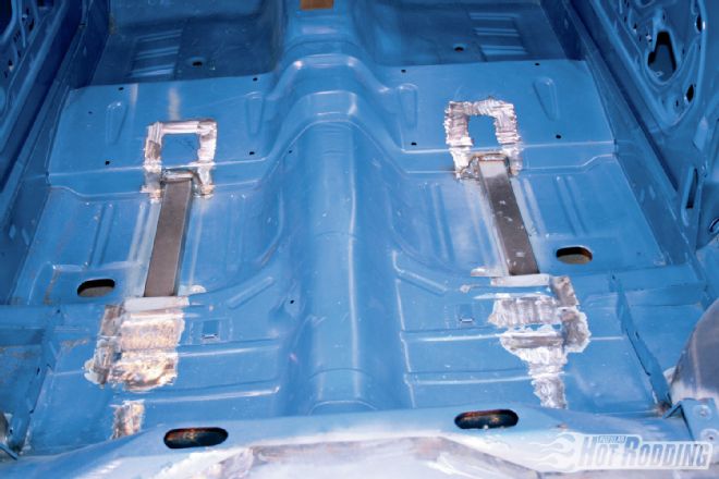 18. Although the installed subframe connectors protrude into the cabin, the factory carpet will still fit over them without any modification. As for the slight reduction in rear passenger foot room, let ’em get their own Mustang!
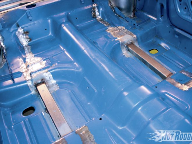
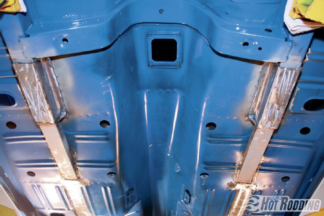 19. The installation procedure for the driver- and passenger-side hardware is identical. By vanishing into the cabin, the DSE subframe connectors offer dramatically improved chassis stiffness without reducing ground clearance. It’s the best of both worlds, as the factory front subframe hangs lower than any part of the subframe connectors.