
Independent front suspension must’ve seemed like impossibly amazing technology to the car-buying public in the mid ’30s. By letting each wheel independently comply with road irregularities it greatly improved traction and ride quality.
While adequate when used in its intended environment along a patchwork of rural highways, these early designs show their age when asked to perform by today’s standards. Their lax caster (specs call for 3/4-degree negative for this ’47 Pontiac) makes steering effortless but robs stability at modern highway speeds. Their high roll centers cause the outside steering tire to roll under in a turn. And because the design doesn’t camber the outside wheel in a turn the tire can’t maintain full contact with the road.
Sure, you can breathe new life into old designs with wider radial tires, by adapting power steering assemblies and disc brakes, altering the uprights to lower the ride height, and even installing dampers that better control the wheels’ motion. But at issue is the cost-to-benefit ratio: those modifications aren’t exactly inexpensive. Nor do they address the root issues like early suspensions’ high roll centers and poor camber curves either.
Swapping the entire suspension for a more sophisticated one usually represents the most effective solution but it’s not without its issues either. A few exceptions withstanding, frames designed for IFS flare out and arch for spring pockets and control-arm mounts.
Two methods exist to update these cars. The subframe method requires cutting the frame at the firewall and grafting to it a portion of frame from a donor vehicle, a job that requires significant fabrication since no two frames come close to matching. The newest ones pushing 30 years old, donor subframes usually require full reconditioning to work properly. And since the most common donor vehicles were engineered in the late ’60s, their geometry isn’t much more sophisticated than the earliest designs. More damning than that, their fixed track width doesn’t always fit properly in recipient cars.
The other method requires creating a frame jig that maintains the chassis alignment and cutting away the area between the firewall and framehorns. Only when the section with the spring pockets and control-arm mounts have been replaced with straight steel tubing will a frame accept an aftermarket crossmember and suspension. Though these aftermarket suspensions boast more sophisticated geometry and can be configured for different track widths, their installation involves labor that most enthusiasts either aren’t capable or willing to perform.
Fatman Fabrications has a third way. It carved a niche for itself by creating entire assemblies to update vehicles originally equipped with independent front suspensions to newer, more technologically advanced systems. These stubs, as Fatman refers to them, consist of a crossmember welded between a pair of rectangular tubes.
Like subframes these stubs replace a portion of a vehicle’s existing frame. However, unlike subframes the stubs match the recipient vehicle’s frame dimensions and duplicate the body mounts, bumper attachment points, and radiator supports. And because Fatman designs them for each vehicle it can tailor the track width to suit the specific application.
The breadth of vehicles that the company addresses boggles the mind: Fatman produces variations of these stubs to fit dozens of vehicles from the ’30s all the way to the ’60s. And while it covers the big players like Mopar, GM, and Ford products, it also covers the orphans—Kaiser, Nash, Packard, and Studebaker owners take note.
Though the individual stub designs vary per application they all have the suspension itself in common. Fatman derived the basic geometry from the proven, versatile, and highly supported Pinto/Mustang II platform. Though not exactly a cutting-edge design anymore, its geometry was quite a bit ahead of its time and far more sophisticated than the cars it went under. It has a relatively low roll center for good turn-in qualities, a camber curve that keeps the tire treads planted squarely on the ground in aggressive corners, and an antidive geometry that counters weight transfer under braking. Add rack-and-pinion steering to the mix and it’s clear why the industry so widely embraced it.
The particular setup we’re showing features tubular control arms but the upper units, the springs, dampers, knuckles (spindles), and steering rack, are functionally interchangeable to the OEM pieces. In fact, some Fatman crossmembers can use Mustang II components with some modifications. As you’re probably familiar, just about every brake combination fits the stock height and dropped versions of the knuckles.
What follows is how Marshall Woolery at Thun Field Rod & Custom installed a Fatman stub on a customer’s late-’40s Pontiac. Though the installation instructions describe the variations among models they can’t address the pitfalls that threaten every install.
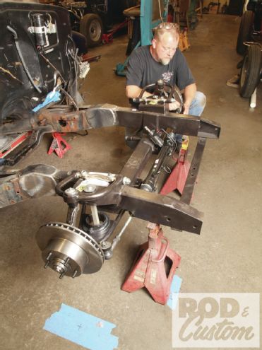 1 Though specific to ’40s Pontiacs, this kit largely resembles the ones intended for others in the GM family. What follows explains the installation procedure for nearly every other stub kit Fatman offers.
 2 Begin by setting the entire chassis on at least four stands. If supported only by a pair of stands the vehicle will likely move after the front of the frame comes off. Time spent leveling the frame will pay off in simplified and faster measurements later on.
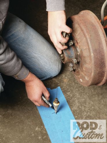 3 At ride height the wheels sat properly in the front wells so Woolery plotted their location on the ground. It’s best to remove the springs and duplicate the suspension settings that locate the wheels properly in the wells. Some suspensions make the wheel move longitudinally as it moves vertically.
 4 It’s also a good idea to plot the bumper holes’ location and height. Wheel location prevails but until the suspension is complete this will serve as a guide. Remember to measure from the center of the holes.
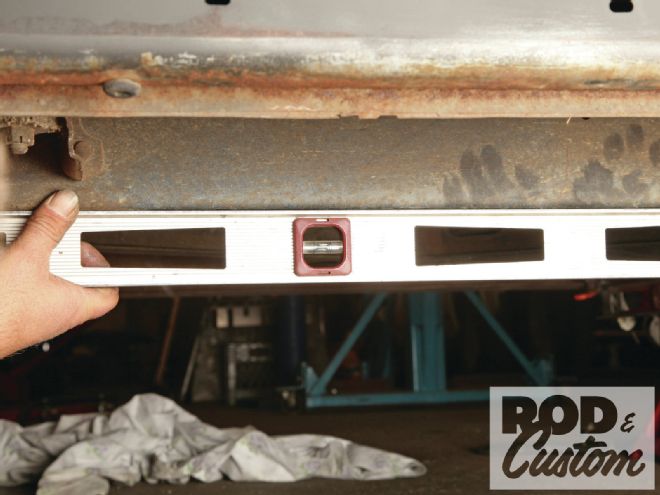
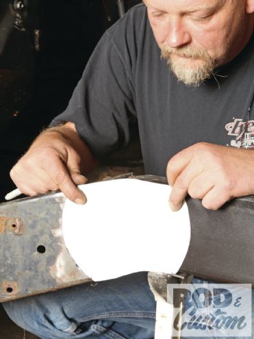
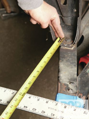 5 The instructions specify measuring forward from the centerline of a body-mounting hole to establish the cut lines. Woolery laid a long straightedge across the frame and measured both points before marking the lines.
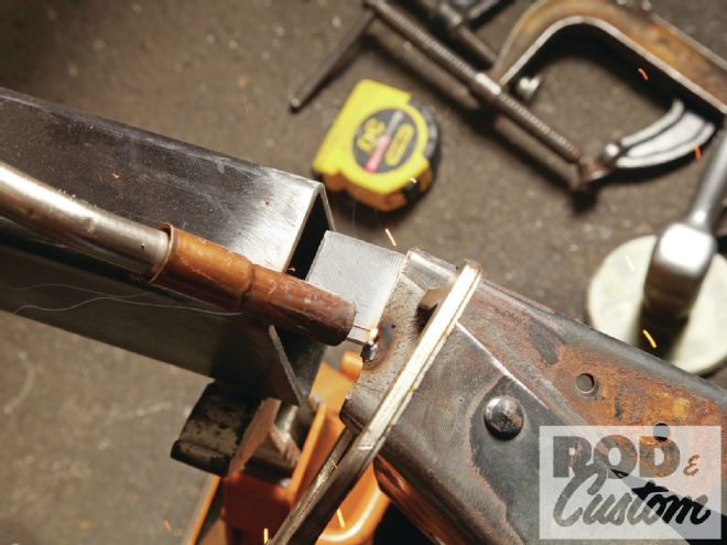
 6 Here’s another reason to set the chassis level: Fatman cuts the ends of the stub perfectly square. So a dead-vertical cut ensures a tight fit between the chassis and stub. Woolery cut along that line.
7 We began to wonder if something was awry when we noticed that the spread of the stub differed from the frame spread. Anticipating grief we merely tacked the stub in place.
6 Here’s another reason to set the chassis level: Fatman cuts the ends of the stub perfectly square. So a dead-vertical cut ensures a tight fit between the chassis and stub. Woolery cut along that line.
7 We began to wonder if something was awry when we noticed that the spread of the stub differed from the frame spread. Anticipating grief we merely tacked the stub in place.
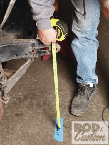
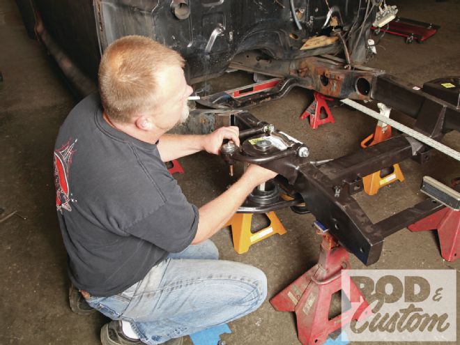 8 Rather than trusting the crossmember centerline to represent axle centerline, a gun-shy Woolery mocked the suspension and measured from the spindle itself. The plumb bob confirmed our fears: the axle centerline came up short.
 9 The incorrect axle centerline underscores the importance of installing complex assemblies by actual measurements based on real parts on a car rather than by a figure on a sheet of paper. Pontiac may have drilled the mounting hole in the wrong spot and altered the bracket to fit. In retrospect it would’ve been wiser to cut the frame slightly long and trim it back until the crossmember centerline aligned with the axle centerline marks on the floor.
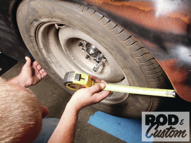
10 Woolery shrugged and went about measuring the wheel’s position in the arch. He could’ve just referenced the line marked on the floor but knowing the degree of misalignment offers keener insight.
9 The incorrect axle centerline underscores the importance of installing complex assemblies by actual measurements based on real parts on a car rather than by a figure on a sheet of paper. Pontiac may have drilled the mounting hole in the wrong spot and altered the bracket to fit. In retrospect it would’ve been wiser to cut the frame slightly long and trim it back until the crossmember centerline aligned with the axle centerline marks on the floor.
10 Woolery shrugged and went about measuring the wheel’s position in the arch. He could’ve just referenced the line marked on the floor but knowing the degree of misalignment offers keener insight.
Here’s the pitfall we encountered. According to Fatman, the body-mounting locations vary even within a year’s production on Packards, Oldsmobiles, and Pontiacs. This particular car’s owner plays an active role in his car’s construction so he took it upon himself to order the parts. He did his due diligence and consulted Fatman’s techs who described how to measure the chassis. Fatman’s people, armed with the measurements, chose the appropriate stub to send.
Call him skeptical but after decades of doing things to old cars Woolery knows to expect the unexpected. Case in point, last year we showed how he installed another manufacturer’s subframe in a ’39 Chevy. Because someone along the line didn’t bother to ask if the car came equipped with IFS or a beam axle (and yes, there is a difference) and because we didn’t know to tell, there was a 50-50 chance the wrong one would arrive. Well, tails we lost. But because early on Woolery plotted all of the chassis and suspension’s locations on the floor he had a roadmap to follow. He lightly modified the crossmember and voilà, it fit.
Well, tails we lost again. Despite the homework the stub came up short—about 3/4-inch too short in fact. But once again rather than point fingers we shrugged it off and made the parts fit. The extra little bit of work has a silver lining, though: regardless of what you install you know to document every component location and to cut parts long and trim them to fit. And to be fair any invasive chassis modification like this benefits from the type of reinforcement Woolery built into this job.
There are some design considerations with this particular model stub. The kit has a pretty wide track. It’s close to the factory track width, which shouldn’t present any problems if using narrow tires on OEM-style wheels; however, wider wheels and tires will require some careful planning.
In a nutshell this kit favors wheels with a considerable amount of positive offset (greater backspace or the distance between the wheel’s backside and its mounting flange). Wheels that have a separate rim and center (most steel wheels and many aluminum ones) can be easily configured to work perfectly. However, wheels with fixed offset (most one-piece cast alloys) usually don’t have much positive offset and may not work so well. Case in point, the 225/60R16 tire we mocked on the car isn’t excessively wide but the zero-offset wheel it mounts on made the tread interfere with the fender opening.
To be fair, a zero-offset wheel would create fit problems with most cars. A wheel with greater positive offset (same width but additional backspace) would move the tires back into the fenders and out of the danger zone. Or, if you’re dead set on running a particular wheel with a zero or negative offset, ask about the narrow control arms that Fatman offers.
All in all the kit works incredibly well. Not including the sheetmetal and drivetrain removal we made the swap and had the car back on the ground within a day (hobbyists with an average tool selection would do well to budget a day for prep, a day for install and suspension assembly, and at least another day for engine mounts and body reassembly). It also reduces an incredibly difficult task to one that most experienced amateurs with welding skills and modest tools can accomplish. Yes, even the solution to the problem we encountered is easy.
And best of all, these stubs bestow cars with early IFS the handling and ride characteristics we’ve come to expect. When properly set up there’s no reason an old car can’t keep up with or even outperform modern traffic.
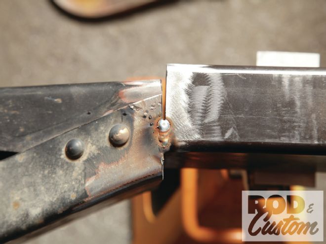
 11 After cutting the tack Woolery pulled the stub away from the frame and tacked this tab to the inside of the frame. It serves no structural purpose beyond holding the stub in place for the following process.
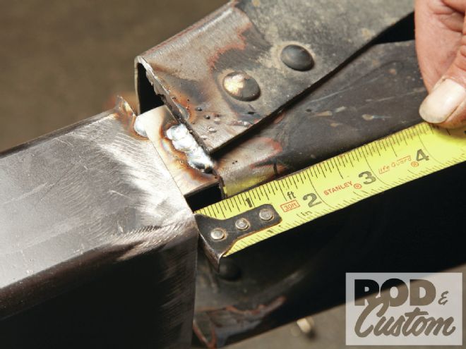 12 Woolery set the stub back in place, this time 3/4-inch ahead of where it was. Content with the new location, he tacked the tab to the stub. Again, the tabs merely hold the stub in place for mocking purposes.
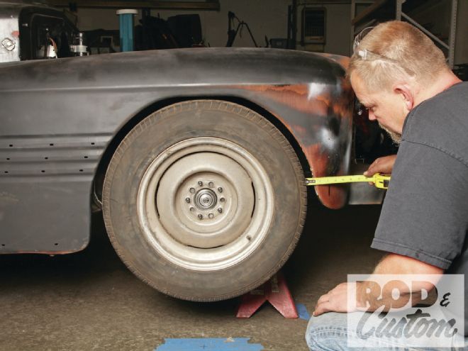 13 Once again we set the car’s clip back in place. As we suspected the tires landed in the exact spot we intended. At this ride height (more than 2 inches lower than stock with stock-height knuckles and springs) the wheel and arch radii match and the tire’s 27-inch diameter fills that arch perfectly.
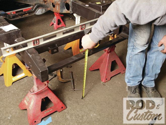 14 Happy with the location, Woolery measured the stub’s location. Though he measured diagonally across the body mounting points he also measured its location relative to a few points on the body. That determines if the chassis is actually plumb with the body.
15 Woolery also confirmed the height, this time at the bumper mounts and radiator core support (shown here).
14 Happy with the location, Woolery measured the stub’s location. Though he measured diagonally across the body mounting points he also measured its location relative to a few points on the body. That determines if the chassis is actually plumb with the body.
15 Woolery also confirmed the height, this time at the bumper mounts and radiator core support (shown here).
 16 Even if the stub butted tight against the frame one problem would have remained: the clip’s spread would’ve still ended up too narrow. Woolery addressed both issues by creating templates for fishplates, joint strengtheners common in the rail and fabrication world. A portable bandsaw would cut these perfectly at little expense.
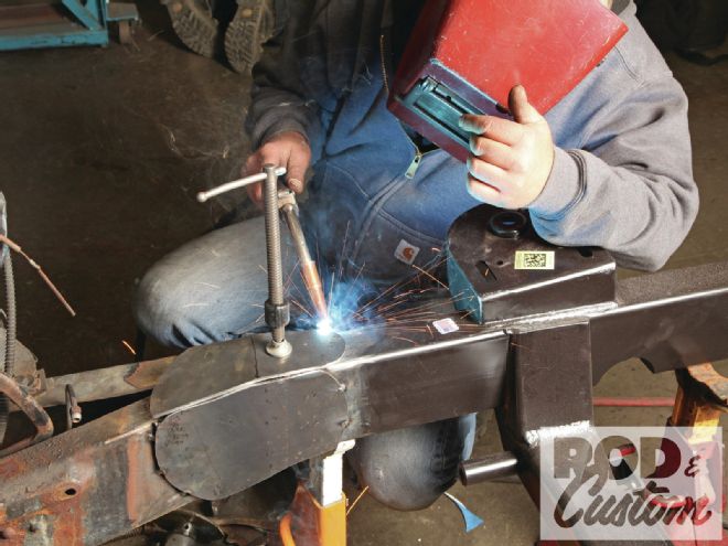 17 The 1/8-inch-thick fishplates box all four sides of the joint. Once welded along all seams, the plates merge the frame halves into one piece by a joint that exceeds the strength of the individual parts. In other words, if the frame failed it would do so anywhere except at this joint.
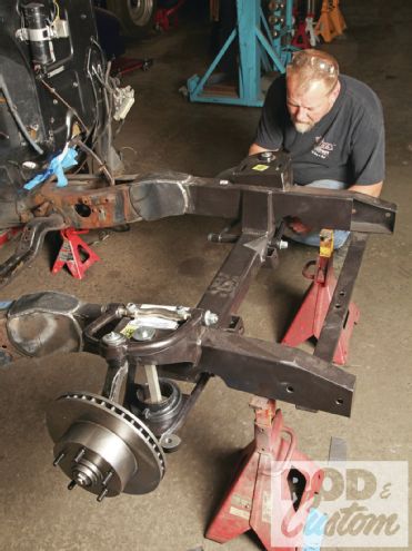 18 Satisfied with the installation, Woolery reassembled the front suspension, including the steering rack (included in the complete versions of the clip but not shown).
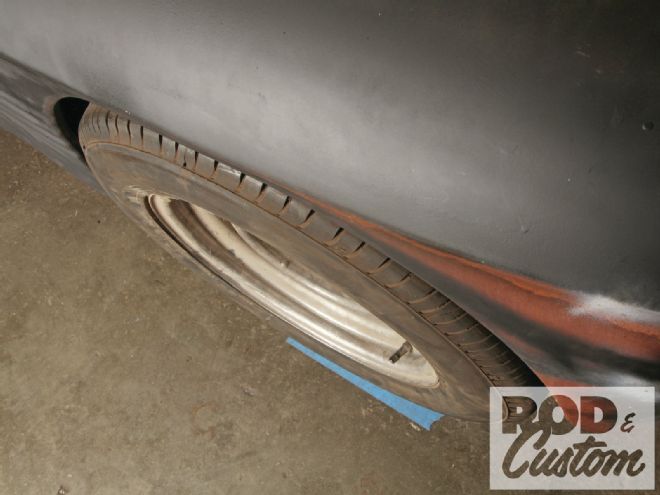 19 In closing we feel obligated to reveal one thing about this particular setup. These kits require either a positive-offset wheel or narrowed control arms and tie rods. But to be fair this 16x7 wheel has zero offset, which would cause problems on many other cars.
Sources
Thun Field Rod & Custom
(253) 677-9526