Steering components, steering system design, and installation are not as glamorous of subjects as high-performance engines, the latest finishes, or the current upholstery trends. However, the components that make up your steering system are just as important as the brakes, suspension, shocks, and other less enticing parts that make up a good-handling street rod.
Early hot rods, as well has many traditional hot rods, utilize the early Ford F-1 and F-100 pickup truck steering box. If you are into the through-the-cowl side steering, you may be using the venerable race car steering box from Schroeder Racing Products, a worm-and-sector box, and while they serve the purpose they are still fairly hard to turn, and the heavier the automobile, the more effort it takes. Most worm-and-sector steering is of the push/pull variety, meaning the drag link runs parallel to the framerail and pushes and pulls the steering arm.
The next step up in steering came with the reciprocating ball steering boxes. Like the early Ford Mustang, the Corvair, and the highly popular Vega-style steering boxes, the reciprocating ball design is still a worm-and-sector, but ball bearings are encased in races that ride up and down the worm gear as the sector rotates, thus taking less effort to turn the wheels. While the Mustang and reversed Corvair boxes are used most often in street rods in a push/pull application, the Vega style introduced cross steering to the street rod arena. Unlike the push/pull design, the cross-steer system has the drag link running parallel to the tie rod or crossing from left to right; this design lessens the bumpsteer, which is prevalent in transverse front spring suspensions, and even more prevalent in the push/pull design.
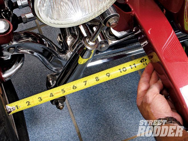 Before removing any components, we positioned the front wheels in the straight-ahead position by measuring the distance between the inside of the front wheel and the frame on both sides; equal measurements ensured the wheels were in a straight-ahead position. We were also able to verify this by lining up the paint marks (register marks) that were still visible on the Vega-style steering box. These paint marks set the box at the halfway mark of the full rotation, which if installed correctly sets the front wheels at the straight-ahead position. (9 minutes)
European cars and performance cars began using the rack-and-pinion style of steering in the early 1950s, and American manufacturers eventually followed suit. Just as the name implies, the pinion gear rotates left and right and moves a rack-a straight piece of steel with teeth cut into it. The advantage of rack-and-pinion steering is a superior steering feel due to less play and a more direct action as the steering wheel is turned, rotating the pinion gear, and thus moving the rack to the left or right. OEM rack-and-pinion units consisted of a long rack, enclosed in a fairly long tube. These worked well on larger street rods and fullsize automobiles but were not easily adapted to early model street rods.
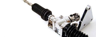
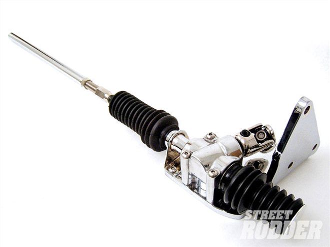
Now that has all changed, as the Unisteer division of Maval Manufacturing has designed a rack (half-rack) that is a direct replacement for the popular Vega-style steering box when used in a cross-steer application. While we were satisfied with our Vega-style steering, we decided to install a Unisteer rack-and-pinion unit in our '32 Ford highboy roadster. We wanted to find out if it was truly a bolt-on application, if it was really as simple to install as the literature states, and most importantly, if the rack-and-pinion unit improved the steering characteristics of our hot rod. Follow along as we track the time and effort involved in installing the unit and evaluate the results.
Some Notes Of Interest
The female coupler and the splined adapter shaft will not be required if you are installing the Unisteer unit in a new build. You can design your steering shaft(s) to connect directly to the Unisteer rack-and-pinion input shaft. You can order the Unisteer rack-and-pinion unit with or without the female coupler and the splined adapter shaft.
We found the standard 16-inch-long Unisteer drag link was too long or too short on a few installations, about 1 percent. Drag links are available from Unisteer 1 inch longer and 1 inch shorter than the standard 16-inch model. When ordering, supply the tie-rod length and the folks at Unisteer will get you the correct drag link.
We found the exhaust ran around the front of the engine and interfered with the rack-and-pinion assembly on one application. A call to the tech guys at Unisteer resulted in a mounting bracket that lowered the steering unit 1 inch, all we needed to clear the exhaust. In addition, Unisteer has both weld-on and chrome-plated brackets. Unisteer also manufactures a left-hand-drive unit for street rodders who drive on the left side of the highway (on purpose).
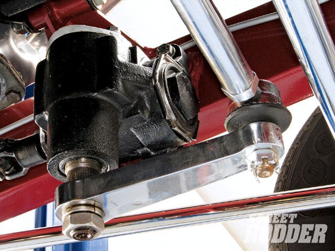 This was the existing Vega-style steering box. Note there are yellow paint marks on the shaft and housing, if they have not worn off, so the wheels are in the straight-ahead position if these marks are lined up.
The installation was as simple as advertised, the steering is much quicker, and the feel of the road is much improved.
On the down side, the turning radius is less than with the Vega-style box. However, we can still get through the drive-through at the donut shop, turn corners, and perform the normal turning operations, so the quicker steering and the better road feel is well worth the trade-off.
Since we already had the car up on the lift (we have done installations with the car up on jackstands, as well) and were working on the steering, we decided to install a steering damper from the guys at SO-CAL Speed Shop. These shock-absorbing units are designed to absorb the bumpsteer that is prevalent in transverse front spring vehicles. The steering damper comes with stainless steel hardware, antiseize compound, and easy-to-follow instructions.
The installation requires disconnecting the forward or rear connection of the lower right front (passenger side) bar in four-bar applications or disconnecting the upper and lower connections of the hairpin radius rod. In either case, you must remove the clevis, rod end, or bushing in order to slide the damper mounting bracket over the radius rod. We marked the lower rod end, lock nut, and radius rod and counted the revolutions required to remove the rod end in order to reinstall it in the same location. We followed SO-CAL's recommendation and used new lock nuts when we reinstalled the radius rod.
The installation also requires removing the tie-rod end on the passenger side. Before removing the tie-rod end, we marked the tie rod, lock nut, and the tie-rod end itself. You must reinstall the tie rod into the steering arm in its original location (without moving the wheels) in order to keep the correct steering geometry. After we removed the tie rod from the steering arm, we removed the tie-rod end from the tie rod, counting the revolutions required to remove it. This gave us another reference to enable us to reinstall the tie rod in its original position. With the tie-rod end removed, we were able to slide the steering damper mounting clamp over the tie rod. The tie-rod end was then reinstalled into the tie rod, and the tie rod was reinstalled into the steering arm in its original position. After tightening the castle nut on the tie-rod end, we lined up the nut with the hole in the tie-rod end and installed a new cotter pin.
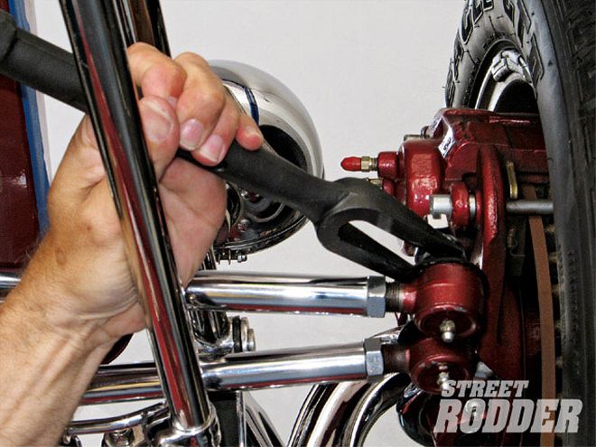 You may need to use a tie-rod end removal tool , or pickle fork, if the tie-rod end fit is extremely tight.
With the brackets installed on the car, we extended the damper to its fully extended position and measured the full length of travel. We then marked the damper shaft at the half-travel mark and closed the shaft to that mark. This is the installed position of travel. We mounted the radius-rod end of the damper to the installed clamp after applying antiseize compound to the bolts and followed suit with the tie-rod end, making sure we installed the supplied spacer. Saving the lock nuts for final installation, we used standard nuts and tightened the clamps. We then turned the wheels fully in both directions, ensuring the unit did not interfere with any components and did not run out of travel before the wheels were at the fully locked left and right positions. With no interference issues and plenty of free travel in the steering damper, we removed the regular nuts and replaced them with the supplied lock nuts.
The steering damper installation took about an hour and a half. SO-CAL recommends the frontend be realigned by a professional alignment shop after installation to ensure proper steering geometry.