
This ol’ F-100 was purchased with the intent of fixing it up a bit and reselling itthat’s what I told my wife, anyway. Bodywise it was in great shape. It required the minimal rust repair in the usual fender spots, but, overall, it was a great candidate for a face-lift. A Mustang II IFS system had already been installed, and it was outfitted with what appeared to be a fresh 350 Chevy and TH400 trans. Unfortunately, the motor had been mounted so the distributor cap was jammed up against the firewall, making removal of the cap impossible. Also, the throttle linkage rubbed the side of it when going through its travel. It had a good fan shroud on the radiator, but the fan was 3 inches from even coming close to being inside the shroud, so an electric fan had been mounted in front of the radiator.
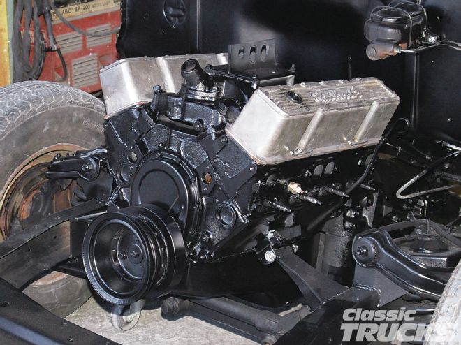
The haphazard motor mount brackets just had to go. The rectangular tube that had been used for the motor mounts was strong and a pretty common material to use. As part of my repairs I’ll use some 3/16-inch plate and come up with something a little better looking and just as strong.
My first chore was to get to the motor and remove it. This being a ’56 Ford, the tips are based on this model, but are similar to other years and makes. This truck was being repainted, so the fenders were removed leaving the radiator and front air dams on the radiator mount. As is the case with most pickups, the F-100’s front sheetmetal can be removed by just removing the bolts at the rear of the front fenders and the bolts/studs under the radiator mount. With the bolts removed and a guy on each side, we lifted the radiator end up to clear the crossmember then lifted the back to clear the tires allowing us to take the whole front end off as one unit.
With the engine/trans removed, I used a plasma cutter to remove the old mounts and an electric grinder with a hard stone to get rid of the evidence. I knew basically where the new motor mounts were going to end up on the framerails so I made sure to grind and sand those areas just in front of the crossmember before the engine went in for fit. This truck needed a new trans mount too, because the previous quality in mounting of the motor, reflected in the construction of the trans mount as well. The replacement I used is from Classic Performance Products. (I use ’em for most of my suspension, brake, chassis, and steering needs as they cover multiple years, makes, and models of pickups and muscle cars. Plus, their catalog is filled with great swapping and construction tips as well.)
The CPP trans mount simply bolts to the bottom of the framerail with four 38-inch bolts and accepts Ford or Chevy transmissions. The width of the mount is also narrow enough that it will fit on top of the framerail for mounting, too (if that works better). Proper placement of the trans mount is the first thing you need to determine before moving onto the motor mount installation. It’s a lot easier to make your engine mounts when the trans is mounted solid. When installing a small-block Chevy and TH400 trans, start by clamping the trans mount to the frame so the forward edge of the trans mount is even with the back edge of the front running board mount bracket (in the case of an F-100). With TH350s you can move the mount forward an inch or so; this is also a good starting point for small-block Fords. This should get you close to where the motor needs to be in a front-to-rear relation. Then, I slid the motor and trans into place to see how it was going to fit. When I got it in I saw why the last guy mounted it the way he had. The oil pan and Mustang II crossmember had a bit of a clearance problem. This required some modification to the crossmember. After making some reference marks on the crossmember for the oil pan width and forward edge, I removed the engine/trans and laid down some accurate cut lines, plasma cut out the needed material, and ground the edges smooth. With some card stock, I made up templates for the filler pieces I needed and cut them out of 1/8-inch plate. They were then tacked in place.
Back in went the engine and trans, and the oil pan fit perfectly in the new notch in the front crossmember. This, in turn, allowed the proper positioning of the fan and shroud. In this case, other usually critical clearances didn’t need checking. I had plenty of steering/exhaust clearance, the trans pan cleared the stock trans mount crossmember, the engine-to-firewall clearance problem was solved, and the oil pan cleared the rack-and-pinion. Once I was pleased with where the engine sat, I drilled the needed holes to bolt up the trans mount. It’s a good idea as you’re bolting the transmission to the mount to double-check that the trans is centered in the frame. In my case the measurement to center was 17 inches. Drilling those holes in the frame is never my favorite part. I always start with a small drill first, say 3/16 or so, then 5/16, and then the needed 3/8 inch. With those chores done I’d completed the hardest part of the motor/trans mount install.
With the trans bolted down I was able to adjust the engine angle if needed. In my case the fan and shroud determined the angle the engine ended up sitting; it’s in the 3-degree range. That’s a good angle. The carb-mounting surface of the intake is usually level. If you’re running your truck with the hot rod stance, the engine will usually end up level when the truck is at ride height. With the engine centered and where I needed it, I cut some tubing to start the motor mounts. These mounts are just the basic nonlocking style. Applicationwise they were used on all GM cars and trucks in the ’60s and into the early ’70s I think. They fit small- and big-blocks. The tube is 7/8-inch tubing with a 7/16-inch hole in it. GMs use a 7/16-inch bolt, and Fords use a 1/2-inch bolt. The next step was to install the tube in the mount. If you’re going to try this yourself, and the motor mount bolthole is slotted, as in this case, tighten the bolt and tube almost at the top of the slot. You need the tube to stay right there. Then break out some card stock and start cutting it up until you come up with a design you like. The one shown here is one I’ve made for years--Ford or Chevy. The Ford’s tube is just a little bit longer and that part of the mount ends up a little bit wider than the Chevy’s. Once you’ve got your pattern, transfer it on some 3/16-inch mild steel plate and cut them out. Shape with a grinder, and check your fit as you go. When it’s shaped and ready, tack it to the tube and to the rail/ boxing plate. Get the card stock back out and create a gusset for underneath the top piece. This gusset should wrap at least halfway around the tube also. Again, when you have them ground, shaped, and fit, tack them in place. You want some good tacks on them just in case you bump the mounts when removing the engine to do the final welding.
After things were all tacked in place, I removed the engine and trans and did my finish-welding, but it can be done with the engine still in. Usually, though, the front frame section gets painted and the brake lines are bent up and installed before I reinstall the engine and trans.
If you’re using this article as a guide the following images show what kind of mount you should have ended up with--strong and rather stylish. It’s a lot better than the rectangular tube I started with, plus I can get the distributor cap off and even turn it to adjust the timing, all helpful things. With everything painted and reinstalled the fun begins--adding all the details in the reassembly. CT