Many car crafters roll their eyes and tune out when bench racing turns to electronic fuel injection (EFI). We're not here to hijack you into believing that EFI is cheap or even simple. Carburetors will always have their place. And yes, EFI is more expensive and more complex. That's old news. Even if you never take the opportunity to apply what EFI can do for an older muscle-car, it's still worth learning the basics of electronic engine control. What this all comes down to is that the more you know about EFI, the less intimidating it becomes. Don't worry; there's no test at the end, and we promise not to whack your knuckles with a yardstick if you lose focus for a second or two.
Basic Components
While electronic fuel-injection systems became the norm during the 1980s, these were advanced digital versions of simple designs that were first developed back in the mid-'50s. The first domestic-production EFI system appeared as the Electrojector on the '57 Rambler Rebel, using vacuum tubes instead of microchips. Chrysler also dabbled with EFI in the late '50s with disappointing results. Bosch is generally given credit for the first true full-production-run EFI system 10 years later on the '67 Volkswagen using D-Jetronic FI. So EFI has been around for more than 50 years.
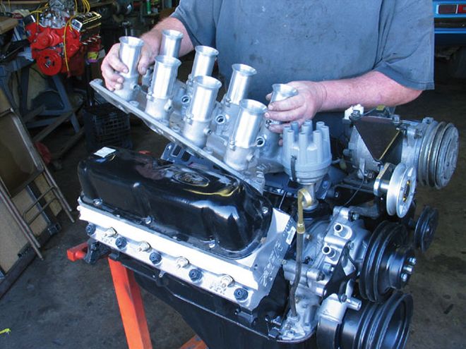
The cool thing about EFI is that any kind of intake manifold can be converted to electronic control. This Enderle was originally designed for mechanical fuel injection, but builder Tim Moore is converting it over for EFI control on a small-block Ford.
Before we get into how EFI works, we should start by looking at the components. The computer is the brain of the system and is the control mechanism often called the electronic control unit or module (ECU or ECM). Lately, both factory and aftermarket systems are integrating automatic transmission controls into the ECM and referring to these as either powertrain control modules (PCMs) or vehicle control modules (VCMs).
In order for the ECM to make proper decisions about air/fuel ratio or spark timing, it requires a voluminous stream of sensor information. For a bare-minimum EFI speed-density system to operate, it needs to know engine rpm, throttle position (TPS), engine load from intake-manifold vacuum (manifold absolute pressure or MAP), and preferably coolant temperature (CLT). Along the way, factory and aftermarket EFI systems have added mass airflow (MAF), knock sensors, inlet air-temperature sensors, and oxygen sensors. Most of these are designed to inform the computer of engine conditions leading up to the combustion event and operate on a very simple system that converts a physical property like coolant temperature or manifold vacuum into voltage. Automotive sensors generally operate on a 0- to 5-volt scale.
The oxygen sensor, usually placed in the exhaust stream ahead of a catalytic converter, is the only feedback sensor that informs the computer of what happened after the combustion process. The oxygen sensor reads the amount of free oxygen in the exhaust, converting those levels into voltage. This information is extremely useful to the computer to help it maintain a given air/fuel ratio while the engine runs down the road. All gasoline-fueled production EFI engines are designed to run at part-throttle at the lowest common exhaust emissions level achieved at 14.7:1 air/fuel ratio, something engineers call stoichiometric, or ideal chemical balance. At part-throttle, the ECM helps the engine maintain that 14.7:1 air/fuel ratio. At WOT, when maximum power is demanded, the computer must adjust the air/fuel ratio to a richer 12.5:1 to 13.0:1.
We also have to have a way to accurately introduce fuel into the engine. Most performance fuel-injection packages employ a multipoint system that specifies one injector per cylinder. These multiple injectors are then fed fuel at high pressure through a common fuel rail. Generally, most multipoint systems are designed to run at 3 bar (three times atmospheric pressure: 3 x 14.7 = 44 psi). One bar is actually 0.9869 of an atmosphere, which is why 43.5 is the 3-bar pressure reference number. With a set pressure, the volume of fuel the injector can deliver is determined by the amount of time the injector is open. This is called the injector pulse width. Properly sizing the injectors improves part-throttle performance because oversized injectors are difficult to control at very short pulse widths.
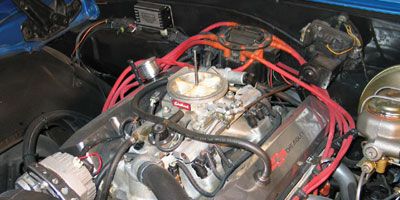
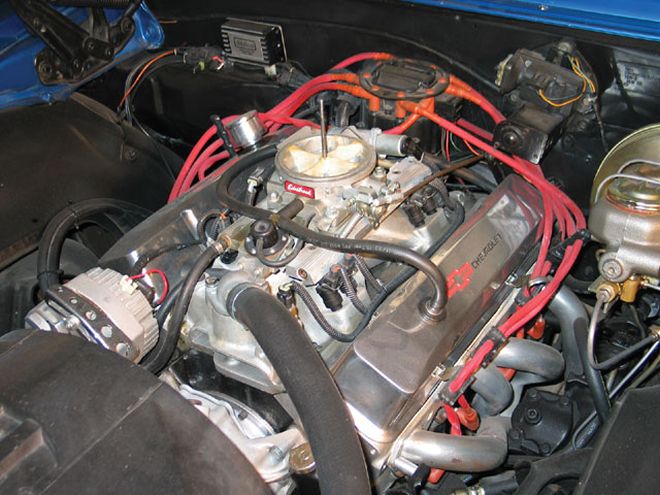 This is a typical multipoint fuel-injection package, specifically one of Edelbrock's Pro-Flo systems, on a small-block Chevy. The Pro-Flo differs slightly from most others in that it uses a handheld calibration module instead of a laptop computer to make changes to the fuel or spark curve.
Finally, all OEM and most aftermarket EFI systems also offer digital spark control. In the last few years, the OEs have elected to drop the distributor in favor of a distributorless ignition system (DIS). In this approach, the ECM needs a crank trigger to tell it when the No. 1 cylinder is at top dead center (TDC). Most engines also use a cam sensor (although it's not absolutely necessary) to tell the computer when the engine is at TDC on the firing stroke. Then the computer can trigger each individual spark-plug coil to light the fire in each cylinder much more accurately than a distributor with all its additional motion and clearances.
Systems Approach
EFI can be separated into three basic control configurations: alpha-N, speed density, and mass airflow systems. Alpha-N is the simplest, with the most complex name. This system requires input only from engine rpm and throttle position as input for the base fuel map and is mainly used for race engines operating primarily at wide-open throttle (WOT); no manifold pressure sensor is required. This is a very crude system and not recommended for street-engine operation.
Speed density is the most popular electronic fuel-control system and is also very simple, relying on engine speed and intake-manifold vacuum measured by a manifold absolute pressure (MAP) sensor. If you look at a speed-density base fuel map, it matches engine speed with a given amount of engine load (measured by the MAP sensor). Think of the MAP sensor as a digital vacuum gauge. High manifold vacuum at any given engine speed means there is very little throttle opening and therefore minimal load on the engine. A high engine speed with near zero manifold pressure means the throttle is at WOT and load is high. Given any combination of load and rpm, the base fuel map delivers a given amount of fuel. The trick here is building a base fuel map that accurately assigns the correct amount of fuel for each of these load situations for best efficiency and/or best power.
The limitation of speed density is that the engine does not measure the amount of air it uses, so the tuner must estimate how much fuel to use. Most current speed-density systems now use a wide-band oxygen sensor to aid in tuning the fuel curve. By actually measuring the amount of air that the engine breathes in, we can more accurately meter the proper amount of fuel. That's the job of a mass airflow (MAF) sensor. The limitation of this system is that most production MAF sensors are small, restricting the total volume of air they can flow. Plus, adding a MAF sensor increases both complexity and cost. This is why most aftermarket EFI systems choose the simpler speed-density design.
Tuning EFI
In the '80s through early '90s, performance enthusiasts shunned factory EFI systems because they were difficult and cumbersome to use since any tuning change required burning a new chip. The big advantage of even the earliest aftermarket EFI systems was that they were designed to be quickly and easily modified. All you needed was a laptop, a little bit of computer savvy, and tuning skill. By the mid '90s, the factory realized the advantage of instantly reprogramming their ECMs by merely plugging into the on-board assembly-line diagnostic link (ALDL) port located under the dash. This change to electronically erasable chips (EE-PROM) fueled a move in the aftermarket to the now-famous GM-based HP Tuner and EFI Live programs along with the Ford-compatible TwEECer software packages, which allow enthusiasts to take maximum advantage of the highly sophisticated engine control offered by the factory systems.
This has driven the aftermarket to offer better and more sophisticated systems for true high-performance applications. For example, most aftermarket systems such as ACCEL's DFI, Comp's FAST, and BigStuff3, to name a few, offer options such as nitrous control as an integral part of the tuning structure. This option allows the tuner to control not only several stages of nitrous but also when and how much fuel is added, along with intricate control over how much timing is retarded at each stage. Plus, a few of these units, such as John Meaney's BigStuff3 Gen3 PRO SEFI box, offer mastery over both the engine and an electronic overdrive automatic transmission. If you're a control freak, it doesn't get much better than this because these boxes give you total control over sequential fuel injection where you can make changes in fuel delivery to individual cylinders with feedback from a pair of wide-band oxygen sensors. Plus, they can also drive up to 16 low-impedance fuel injectors. That's serious power. The BigStuff3 SEFI (sequential) box, for example, can also control a complete distributorless ignition system, which allows spark calibrations for individual cylinders.
Aftermarket EFI Maps
The big argument against aftermarket fuel injection is that you have to be some kind of tuning computer wizard/engineer* to be able to tweak an EFI engine to run properly on the street. Much of this reluctance comes from enthusiasts with little computer experience. The truth is that EFI tuning tables and systems have never been simpler. There are only two main maps that control an aftermarket EFI system-one for the fuel and one for spark. These maps are actually simple grids. In the case of a speed-density system, the base fuel map consists of a horizontal scale that specifies engine rpm. The vertical scale is usually expressed in kPa, which is the abbreviation for kilopascals. A pascal is the metric measurement for pressure, with 101 kPa equal to 1 atmosphere, or 14.7 psi. For a normally aspirated engine, the vertical scale would read from around 10, which is very low absolute pressure (equal to high vacuum), on the bottom to 100 kPa (WOT) at the top.
Each intersection point between manifold pressure and rpm represents one combination of engine load and engine rpm. The number in each of those boxes or cells represents the amount of time the injector will remain open, called the injector pulse width. For a typical speed-density map, the lower righthand quadrant of the map would represent high-rpm, WOT engine operation. Tuning is actually very simple. Changing to a larger number in each box increases the amount of fuel delivered to the engine. A smaller number reduces injector flow time, which leans the air/fuel ratio for only that one cell. Tuning is even easier if you combine your efforts with the feedback air/fuel ratio information from a wide-band oxygen sensor with the data-logging capability offered by most of the more sophisticated aftermarket EFI systems.
The spark table operates and is tuned in very similar fashion to the base fuel map. The horizontal and vertical scales are the same. The boxes inside the spark table represent the actual ignition timing. As you may already know, light throttle and light load allow you to put more timing in the engine (just as with vacuum advance), while at WOT at low engine speed you will want to reduce the total amount of timing you put in the engine; otherwise detonation and engine damage may occur.
Most modern aftermarket EFI systems will also create initial fuel and spark maps that will allow almost any engine to start and run and will give you a base from which to begin tuning. Plus, with the growing popularity of aftermarket EFI, complete maps are now out there that car crafters are willing to share with other entry-level users. There are a couple more screens that you need to deal with in terms of acceleration enrichment (similar to the accelerator-pump circuit on a carburetor), idle-quality adjustments, and cold-start features (similar to a carburetor choke), but besides these additions, there's not much more to the basics of EFI tuning. It really is that simple.
Fuel-Injector Sizing
One area that seems to cause more than a little confusion is fuel-injector sizing for a given engine application. While it may sound difficult, it's actually pretty easy. All electronic fuel injectors are sized based on the maximum amount of fuel they can inject, generally expressed in terms of pounds per hour of fuel (lb/hr). This also depends on the fuel pressure at the injector. Most injectors used in the performance industry are rated at 3-bar (43.5 psi). As an example, let's look at a performance injector rated at 40 lb/hr. Multiply that capacity times eight injectors to get 320 lb/hr of fuel. If we assume a generic brake-specific fuel consumption (BSFC) number of 0.50, this means that to make 1 hp for 1 hour at WOT demands 0.50 pounds of fuel. Given this, to find out how much horsepower this size injector can feed, we multiply 40 (lb/hr) x 8 injectors x 2 (to give us 1 pound of fuel to make the math work out), which equals 640 hp. This isn't quite accurate because it would demand 100 percent open time on the injector-called a 100 percent duty cycle. This is very hard on injectors and burns them out, so the typical industry safety margin is 15 percent. So if we multiply 640 x 0.85, we get 544 hp. This is what you could expect a 40-lb/hr injector to safely deliver.
Now let's add some variables. Let's say you've built a killer small-block that can make 500 normally aspirated horsepower and you need to size the injectors, but you are also considering adding a dry 200hp nitrous system that will require the additional fuel from the injectors. The formula for determining injector size is:
Injector size = engine hp x BSFC number of injectors x 0.85 700 hp x 0.5 = 51.5 or a 50 lb/hr injector 8 x 0.85This is a high-flow-rate fuel injector that is also expensive (try $95.95 each for an ACCEL 55 lb/hr injector, PN 74612 from Summit Racing). This size injector is based on the standard fuel pressure of 43.5 psi. Let's say that you already have a set of 40 lb/hr injectors and you don't want to pony up $775 for these larger injectors. Raising the fuel pressure will increase the flow rate of a smaller injector. To determine the flow rate of an injector with a higher fuel pressure, merely divide the new line pressure by the original line pressure, multiply that number times the injector flow rate, and then take the square root of that figure to determine the new injector flow rate. Using the above example, we're going to raise the line pressure from 43.5 to 65 psi. This becomes:
v 65 43.5 x 40 = 48.8 or almost 50 lb/hrThis is not quite enough to satisfy that 700hp package, especially considering that the BSFC for the nitrous horsepower will generally be much less efficient (around 0.60 to 0.65), which will require even more fuel. So you might have to reduce your nitrous appetite by roughly 50 hp (or use a wet system) to give the injectors a little bit of head room to accommodate the fuel required to make that kind of horsepower.
There are also two different types of electronic fuel injectors. The most common is referred to as a high-impedance (12 ohm) injector. The ohm rating is the amount of resistance measured in the injector circuit. These injectors require a small amount of electrical current to operate, are most often used in production-style engines and generally range in capacity from 15 to 44 lb/hr. Higher injector flow rates require more electrical current to operate, creating what are called low-impedance injectors rated at 2 ohms. This additional current requirement also places a greater demand on the electronic injector drivers that are part of the ECM. This means that an ECM designed for high-impedance injectors cannot be used to drive low-impedance injectors. Many higher-end aftermarket EFI ECMs are designed to accommodate low-impedance injectors, but not all ECMs are the same. It's a good idea to check into this if your engine combination will demand injector flow rates above 44 lb/hr.