It has been said many times that an internal combustion engine is nothing more than an air pump, and the more air it can pump, the more power it will make. As with any simplification, it is not all true, but it's a heck of a good place to start. Here, we are going to take a serious look at not only what it takes to get air through an engine, but also how to use it as effectively as possible on the way through.
The number-one flow restriction in any engine is within the cylinder head. Get air to effectively pass these restrictions and you are good to go. It's a big subject to cover, so to chop it down to more manageable bites, we are going to apply five basic rules:
1.Locate the point of greatest restriction, and work on that first.
2. Try to let the air move the way it wants to, not the way you think it should.
3. Air is heavier than you think. Keep the port velocity up and avoid redundant cross-sectional areas.
4. Mixture motion (swirl or tumble, or a combination of both) is important--do not ignore it.
5. Shape is all-important--a shiny finish is not.
Locate the Point of Greatest Restriction
Like it or not, the valves are part of the ports, and when they are closed their ability to flow is exactly zero. This means until they have opened quite a way, the valve is the main restriction to the engine's airflow. Even when the valve is at a decent lift, it still presents a tortuous path for the air to travel on its way into or out of the cylinder. Making a comparison of the valve's ability to flow compared to the rest of the port on a stock production small-block Chevy head demonstrates just how much of an impediment the valve is even when it is wide open.
First the main body, Section A. This is a highly flow efficient, rectangular cross-section straight tube and flows 300 cfm. Section B, the turn into the seat area, flows some 200 cfm. Now let's consider section C. This is the only part of a port that has a moving component--the valve. When the valve is seated, flow is zero. If the valve is lifted high enough, it moves beyond the seat's influence, but to do so takes a lot of lift. In practice, half the valve's typical full lift is about representative of its average flow potential. In our example, this is about 140 cfm. From this we can see that at some small amount of valve lift, flow restriction is 99 percent at the valve seat and one percent in the port. At very high valve lift (.75 inch or more) this situation is pretty much reversed.
Our number-one priority then is to make the valve capable of passing as much air as possible--whatever the lift involved. To do this we need to address both size and efficiency. What we are searching for is the biggest effective valve.
Having identified the most restrictive point along the engine's gas flow path, let's see what can be done to improve it. Although it may be the last operation during a porting exercise, the valve seat design is the first priority toward effectively filling a cylinder. So let's look specifically at valve seat design.
Forms for Flow
Let's consider the valve seat isolated from the rest of the port. Fig 2 shows a progression from a very basic form "A" where the throat of the port is exactly the same size as the valve, to a relatively well-developed form at D. At first sight, it would seem the hole under the valve head needs to be as large as possible so as to flow the most air. Before flow benches became popular, it was often common practice (and often written up as such) to make the valve seat as thin as possible so as to achieve the maximum throat diameter. The flow bench shows this to be a bad move. In reality, maximum flow is always a combination of size and form around the valve before and after the seat. As you can see from Fig 2, the form for the most effective valve/seat/throat combination progresses toward that shown in Fig 3.
Applying the basics outlined for seats will get good results, but to get the max requires a lot of time on a flow bench, as subtle changes can make measurable differences. Often some changes in seat angles are used by top pros to enhance some particular feature. For instance, most Cup car heads have 50- or even 55-degree valve seats. These give up a little low-lift flow, but start to pay back above .5-inch lift. Also, the steeper valve angle acts as an impact damper, reducing the valve's tendency to bounce off the seat at closure time. For big-inch under-valved engines, 30-degree seats can be advantageous, as they make the valve appear bigger than it really is and flow more air during the initial opening phase.
Seats and Port Approach Angles
Air has mass and does not like to hug a port wall around a short-side turn. That is why purpose-built race heads have steeply down-drafted ports. But when heads have to fit under low hoods, port angles have to come down. With low-angle ports, the air (at mid and high valve lifts) does not make it around the short-side turn very well. As a result, most of the air goes out of the long-side turn. This is a situation that becomes more exaggerated the higher the lift becomes. As a result, the streamlining of the port on the long side needs to cater for low, medium and high lifts, while the seat approach on the short side needs only to deal with the requirements of low-lift flow. Fig 4 illustrates what is going on with a low angle of attack port (i.e. less than about 30 degrees).
Valve Shrouding
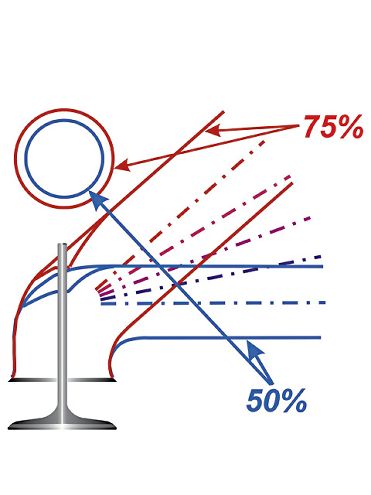
Just so you know, we are still working on rule number one, and the subject is now valve shrouding. Remember, the goal was to have as large and efficient valves as possible. For a typical parallel- or nearly parallel-valve head, valve shrouding is about the biggest impediment to achieving that goal. Worse yet, the bigger the valve gets, the bigger the valve shrouding problem becomes. Valve shrouding seriously impedes flow and starts having a negative impact at about 75 thousandths lift. If we are talking two virtually parallel valves, then the negative effect of shrouding increases until the valve gets to a lift value equal to about a quarter of its diameter, or as it is more often know, 0.25D (Fig 5) If nothing impedes the flow and the air exits uniformly all the way around its circumference, then the valve can be said to be un-shrouded. Unfortunately, few cylinder heads have totally un-shrouded valves. Fig 6 shows the situation for most parallel-valve, two-valve engines. As you can see, the presence of the cylinder wall, and (in this case) the proximity of part of the combustion chamber wall, cuts the area that the air can use to escape from around the valve's circumference. The circles around each valve show how far the cylinder and chamber walls would have to be clear of the valve's periphery to produce an un-shrouded situation. In essence, this would be like having a valve at the bottom of a cone with the walls 38 degrees off being flat (Fig 7).
Be it the intake or exhaust, the worst part of the port for air to negotiate is the short-side turn. If the air fails to make it around the short-side turn, there obviously won't be much air exiting the valve in that area. Since the valve is not being fully utilized around the short side, there is no point in de-shrouding the valve to the extent needed on the long side. A modern high-performance head has little shrouding from the combustion chamber, but be aware, it is possible to cut the chamber wall too much while un-shrouding the valve, especially the exhaust, and pay a performance penalty. This is just one reason why a flow bench is a great asset.
If we were to plot out the flow efficiency of either valve for a parallel two-valve engine, we would find that above 0.25D of valve lift the flow efficiency starts to climb back up from a low. The increase in efficiency starts at a point when the flow stops trying to exit all around the valve and instead "windows" predominantly out one side of the valve (Fig 8). This is why two-valve engines with well-developed ports thrive on ultra-high valve lift. Since I have brought in the subject of "windowing," let's see what the implications are.
Mods to Minimize Shrouding Effects
At this point, we are easing into the application of rule number two. If shrouding is to be minimized, we must take steps to establish what alternative route the air could have to find its way into the chamber in a relatively unimpeded fashion.
A study of the flow into and out of the cylinder of a two-valve engine shows that the principle direction of entry or exit is either toward (for the intake), or away (for the exhaust) from the center of the cylinder. This being the case (and applying rule number two) we need to find a way to let the air flow more nearly along its preferred route. This is done by "port biasing" in the direction the flow wants to "window." This helps reduce the negative effect of shrouding. Applying this biasing technique can make substantial improvements in high-lift flow. Although port bias pays off from mid-lift values, it really comes into its own when lift exceeds 0.25D.
FIG. 9-This theoretical ideal port form progressively accelerates the air into the high-speed section of the port. The velocity it builds can then be converted back to pressure energy at the expansion section. This can help increase the pressure difference across the valve, thus pushing a greater weight of charge into the cylinder.">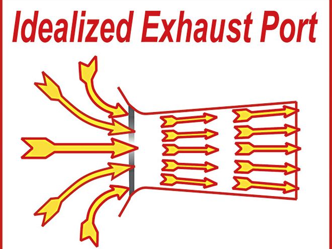 <b>FIG. 9</b>-This theoretical ideal port form progressively accelerates the air into the high-speed section of the port. The velocity it builds can then be converted back to pressure energy at the expansion section. This can help increase the pressure difference across the valve, thus pushing a greater weight of charge into the cylinder.
The Significance Of Velocity
Rule number two will have great significance toward dictating the form of our ports, but to make a completely effective port requires that, at the same time, we also make serious efforts to apply rule number three. Let's start the ball rolling with what we might consider an idealized intake port. Fig 9 shows what an idealized port might look like if building one without a bend in it was feasible. If you think about it, this form holds no big surprises. Essentially, the suction occurring within the cylinder progressively accelerates the air into the tube that constitutes the port and delivers it to the cylinder in the most un-interrupted manner possible. Of course we cannot easily make a port that is straight, but in this idealized form, it does give us some goals to shoot for.
Real-World Ports
Real world ports have a turn in them to accommodate a valve. To more easily visualize how to minimize the shortcomings of a real port, let's make a basic circular port our starting point and look at the moves we can apply to make it better. In Fig 10, we see a representation of our starting point and how it progresses into a more efficient port form. The starting point is a round port with a bend in it to accommodate a valve. This port roughly resembles a 2-liter Pinto engine's intake ports and though they look halfway decent, they only produce a flow efficiency of 45 percent at and above the 0.25D point we discussed earlier. That is not good, but it is typical of a two-valve production head of the pre-'90s era. The number-one problem we have to address is the overly small radius on the short-side turn just before the seat area. For the record, it takes a radius in the order of four inches to get the airflow to stick to the floor of the short side throughout the valve lift range. This means that almost every cylinder head has the short-side turn too tight. This, as you may guess, makes it something of a critical area.
To make the best of the short-side turn, a competent port designer will raise the floor as shown in Fig 10. This produces a more effective short-side turn, but without other changes to what started as a round port, it will reduce the cross-sectional area at the turn. This is almost as bad a situation as having an overly tight short-side turn in the first place. Just like a car, air (at high speed) has momentum. In exactly the same way we have to slow a car for a tight turn, so it is necessary to slow the air to allow it to more effectively make the turn. This is achieved by expanding the sides of the port. This needs to be done to cover both the need to make the turn more effectively, and to compensate for the fact that the valve guide boss and valve stem uses up some of the available cross-sectional area. Unless you know to the contrary, it is tempting to completely cut away whatever guide boss may have originally existed when doing an all-out porting job. This is not a good move as a well-streamlined guide boss can enhance results, especially swirl, rather than hinder them. The way to go is to narrow the guide boss down so that it is barely any wider than the valve guide.
FIG. 11-By applying the simple techniques shown to a basic round cross-section intake port, the high-lift flow efficiency can climb from a typical 45 percent to as high as 65 percent. With extensive flow testing it is possible to get well into the 80 percent range."> <b>FIG. 11</b>-By applying the simple techniques shown to a basic round cross-section intake port, the high-lift flow efficiency can climb from a typical 45 percent to as high as 65 percent. With extensive flow testing it is possible to get well into the 80 percent range.
The combination of a raised floor and expanded walls helps to get the job of filling a cylinder done when the port and valve is feeding a hemi-style chamber or is one of a pair of intake valves in a multi-valve head. If we are dealing with a typical pushrod Chevy, Ford or Chrysler product with two parallel or near-parallel valves, then the port expansion will need to take into account the bias required to enhance high-lift flow. The bias may not need to be quite as much as shown in the last of the port forms of Fig 10, but it does give an idea of where we are going on this subject.
When head modifications are limited to removing metal, dealing with the short-side turn means making the most of whatever is already there. Most production heads and many aftermarket replacement heads have a more abrupt turn than necessary as a result of machining the valve throat below the seat. Rounding this off in the best possible fashion is usually the limit of what can be done to improve the form of the short-side turn.
Once all the avenues toward smoothing out the contours in the valve throat have been carried out, there is little that can be done other than to consider more ambitious moves. One of the best options to get air around the turn to the back of the valve is to slow it down so that it can make that turn. This is where expanding the port's wall area as just discussed can play a significant role. If the port is progressively widened, and for that matter, the roof raised in the turn area, the slowing of the air just before it reaches the valve can pay some substantial dividends. Whatever is done, you should remember that the majority of the air wants to flow in the top half of the port, so that area should be favored when removing metal. This increase in cross-sectional area in the throat (bowl) area can also pay off by converting some of the high velocity into pressure energy, thus helping the charge into the cylinder.
The ports of this Nextel Cup head demonstrate how large a short-side turn needs to be for the air to make it around the turn and still have some semblance of attached flow.
Port Shape & Ram Filling
Up until now, port shape has been our focus of attention. Although we are far from done with port shape, let's turn our attention to port size, or more accurately, port area, as this is about as important as shape. The phrase, "the ports have been opened up," is a no-no. Remember this first. The typical hot rodder's viewpoint that if some is good, more must be better (and too much must be just right) may be good when we are talking cubes, but it absolutely does not work when the subject is port area. Sure, a big hole must flow more than a small one, but when a valve is situated at one end (along with the rest of an engine's mechanical complexities) the whole deal that bigger must be better goes right down the drain. An engine relies far more heavily on ram filling of the cylinder and swirl generation than is often supposed. Ram filling is a function of mass x velocity squared (M x V2).
This means a 10-percent increase produces a velocity 110 percent of its original value, but the momentum goes up by 1.1x1.1, which equals 1.21, for a 21 percent increase. But it's not just any additional cylinder filling that is an issue. At low speed, a slow-moving port can suffer reversion much easier than a faster one. As a result, low-speed output can suffer considerably (Fig 11).With a well-developed combination of cam event timing and cylinder head design, the combination of ramming from a correctly sized port and the returning pressure wave can markedly boost the port pressure just prior to intake valve closure. But the truth is that many engines fail to achieve anything close to the full effect possible because the intake port was simply too big. Part of the reason for this mistake is that air is assumed to be much lighter than it really is. Just to get you grounded in reality, consider that your average school gym contains 50 to 60 tons of air. Knowing this may just be what is needed to have you pay more attention to port velocity than you might have done in the past.
Now that we're clear on the weight of air, let's look at the consequences of having a port that is just the right size for the job. A port (including the part of the intake port in the intake manifold) that is optimally sized will produce a much wider torque band. Why? Higher velocity in the forward direction means any flow reversion that may take place does so at lower rpm. Secondly, peak torque will be higher. Lastly, peak power will be at least the same as a port that is a little too big and significantly more than a port that is way too big.
 This view of a very effective intake port shows how the port expands as it goes around the guide boss. The same technique is applied to the exhaust, but it is not quite as evident in this view.
Determining Intake Port Size
There are two factors to consider when selecting port size. The first is the port area required to make power at the projected rpm. The second is the port area best suited to the valve sizes the head will have. At this point, I am sure the burning question for most of you reading this is "How do I determine exactly what is the right size of ports?" This is a good question and, unfortunately, one with no clear-cut answer as there are so many influential factors. That's the bad news. The good news is there are some good approximations toward achieving a good result the first time around. Just before going into these, let me say that it is better to have a port slightly too small than one slightly too big, as overall performance drops off faster on the big side than on the small side. That said, let us move into the mire of port sizing factors.
The first step toward sizing the intake port area is to start with our idealized port and assume it has a valve and seat design representative of a super efficient real-world example. Given this, we find we can make a good size approximation of the port's parallel section just upstream of the expanded bowl area. This parallel section needs to be about the area of the valve, multiplied by the valve's full-lift flow efficiency. This, for the most part, is very much dependant on how tight the turn is into the bowl and valve seat area. Some thought should make sense of this, as the parallel part of the port does not "see" a certain valve diameter but instead experiences a certain flow value that is ultimately limited by the valve. The lower the flow value of the valve and the last part of the port, the smaller the parallel part needs to be. By controlling the size like this we make the most of the ramming capability without compromising overall port flow. Fig 12 shows what we are shooting for here and some workable numbers to apply.
Putting numbers to the required port area may make it appear that all our port-sizing problems are solved. Unfortunately, that is not quite the case. Using the port areas indicated by Fig 12 will put things close to what is needed, but not necessarily spot on. To produce the figures shown, a few assumptions were made. The biggest of these is that a respectably efficient valve and seat form is used. Also, at the lower port angles, the size of the short side turn has to be at least representative of a good production-style head. In addition to the forgoing, the port sizing also assumes that the cylinder head has valves as large as or nearly as large as can be accommodated within the cylinder.
FIG. 11-These tests, done on a 350 Chevy, show that though the bigger ports flowed about 5 cfm more at .5-inch lift, the smaller, higher-velocity ports produced a much better power curve. At 2,250 rpm, the smaller ports were up by 30 lb-ft. An engine equipped with the bigger ports would need about 25 cubes more to match the low-speed output of the smaller-port heads.">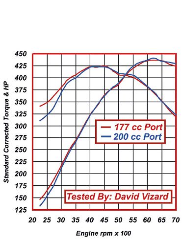 <b>FIG. 11</b>-These tests, done on a 350 Chevy, show that though the bigger ports flowed about 5 cfm more at .5-inch lift, the smaller, higher-velocity ports produced a much better power curve. At 2,250 rpm, the smaller ports were up by 30 lb-ft. An engine equipped with the bigger ports would need about 25 cubes more to match the low-speed output of the smaller-port heads.
The interaction between the parallel section of the port and the valve throat is also a point of significance. By expanding the port to form the valve throat, two things are achieved. First and foremost, the air is slowed so as to give it more opportunity to make it around the short-side turn. Secondly, as alluded to earlier, slowing the air at the throat entrance area converts some of the air's kinetic energy into pressure energy. This is especially important as the piston reaches BDC on its induction stroke. Upping the pressure next to the valve means that this extra pressure is available to literally push more air into the cylinder even though the piston is coming up on the start of the compression stroke. The more kinetic energy there is to do this, the later the valve can be closed. How much does this amount to? Just so you know, it's not trivial. Measurements on a Cup car engine show pressures as much as 7 psi above atmospheric just before valve closure.
All the forgoing may sound a little on the complex side, but it can be easily summed up in one simple sentence: Do not remove metal from a port unless it produces worthwhile flow gains within the valve lift range that will be used.
The Exhaust Port
When the exhaust valve is at relatively low lift, the exhaust gasses can be exiting the seat area at super sonic speeds. During this phase the exhaust responds more to opening area than form. As valve lift increases, the gas velocity drops to subsonic, and port form now becomes the dominant factor toward high flow.
 <b>FIG. 12</b>-The steeper the port angle, the larger the optimum size port is for the valve size used. As the angle is lowered and the short-side turn becomes tighter, so the optimum port diameter drops.
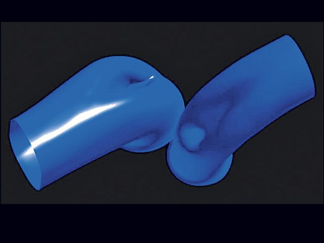
It is also worth noting that for a given size, an exhaust port flows better than an intake. The reason being that as the exhaust passes from the cylinder into the exhaust port, the flow becomes more organized, which is just the opposite of what is seen at the intake valve (Fig 13). Another factor helping the exhaust reach higher flow efficiencies is that the exhaust valve is typically lifted higher in proportion to its diameter than the intake, leaving the valve head to spend more time out of the sphere of influence of the valve seat. Given a port with a steep up-draft angle and a large short-side turn, we can see that an exhaust port begins to resemble a venturi-like nozzle. As such, pressure recovery occurs after the gases have passed through the port's minor diameter. If the port has a reasonable short-side turn and up-draft angle, it will serve well for evacuating the cylinder's spent charge. Because of the way the exhaust works, a good exhaust port must have an effective approach to and from the actual valve seat, otherwise there will be no redemption no matter how good the rest of the port is. As a guide, the minor diameter right under the valve seat needs to be in the region of 85 to 88 percent of the valve diameter. Secondly, the outward taper from the minor diameter needs to be about four to six degrees. At about the time the port area gets to be equal to the valve we can say that, for most practical purposes, it is as large as it needs to be unless the flow bench says otherwise. Along with that, it pays to make sure there are no low-flow or dead spots in the port, as these exaggerate the low-speed losses seen with bigger cams.
Valve SizesAlthough hardly unanimous, there is a common misconception that bigger valves favor top-end power at the expense of low-end power. This is both contrary to results of properly conducted dyno tests and theory. A bigger valve can favor both ends of the rpm range and here's the simple theory to explain why.
As far as a cylinder's capability to induce airflow, a valve that is closed has no size whatsoever. If that valve is opened, say, 20 thousandths, it appears to the cylinder as a small valve. Only when the valve lift reaches the 0.25D point does the cylinder actually "see" anything near the true size of the valve. This means if the cylinder was crammed with valves as big as possible and that proved to be too much (that will never happen), the solution would be not to lift the valve as high. This would then make life easier for the valvetrain. In reality, the critical dimension in the induction and exhaust system for making peak power and torque at a particular rpm is the cross-sectional area of the ports, not the size of the valves.
FIG. 13-A good exhaust port strongly resembles a nozzle. This is one of the reasons why the exhaust flow efficiency numbers are typically higher than the intake.">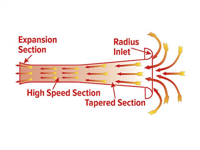 <b>FIG. 13</b>-A good exhaust port strongly resembles a nozzle. This is one of the reasons why the exhaust flow efficiency numbers are typically higher than the intake.
The advantage of using valves as functionally big as possible is that, for a given rate of valve opening, the bigger valves present breathing area to the cylinder faster. This is about the same as a smaller valve opened at higher acceleration rate. Any time we use higher acceleration rates in a valvetrain, it brings about more stress. Getting back to the larger valve, we find (assuming valve shrouding does not become a factor) that the largest possible valves in the head will allow the engine to develop power over the widest rpm range. But beware of so-called back-to-back tests that appear to show the contrary. When larger valves are successfully utilized in a head, it results in an improvement in low- and mid-range flow, not just high-lift flow. If, when dyno tested, such a head results in a loss of low-speed output, it is usually because the overlap area has increased too much. The fix is to re-evaluate the cam's LCA. Such a situation almost always requires a wider LCA.
To sum up the situation on valve sizes, we can say that the biggest valves that deliver the greatest flow are what we should strive for. Now let us look at how we should apportion the space for those valves. The last subject on valve sizes is the apportioning of the intake to exhaust. There is the usual "magazine tech editor" quote that the exhaust flow needs to be 75 percent of the intake. This, unfortunately, is a gross over-simplification, but it does hold reasonably true for normally aspirated engines in the 9 to 12:1 compression ratio range. This also assumes that power is the prime goal and that all the space for valves is used up. The subject of intake-to-exhaust ratio was covered in great detail in our "Compression Comprehension" story in the June '06 issue of PHR, so we won't go into any great detail here. It's sufficient to say that as the compression ratio goes up, the exhaust valve can be made smaller in relation to the intake valve for optimum results. This is because the power happens earlier in the expansion cycle for a high-compression cylinder, thus allowing the exhaust valve to be opened sooner and longer without detriment. This means a smaller exhaust valve can be used, allowing for a bigger intake.
Combustion Chamber Dynamics
Filling the cylinder with plenty of cool air and evacuating the exhaust efficiently at high rpm is a key factor toward making power, but if the combustion dynamics are poor, it seriously sabotages the effort. What happens in the combustion chamber just before, during, and after the spark is fired can make or break any power-producing ambitions, so we will now take a look at what is needed.
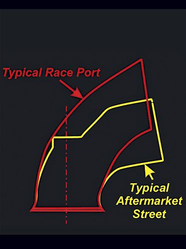 Here is the difference between a typical aftermarket high-performance street head and an all-out race head. At typical street cam lift figures, the advantage of the race head is not very significant in most instances.
At low speed, engine output is all about effective combustion, not cylinder head airflow. Why? Because at low speed there is plenty of time to fill the cylinder. Picking up 50 cfm of cylinder head airflow does little or nothing at 2,000 rpm because there was not an airflow shortage at that speed. On the other hand, 50 additional cfm at 6,000 rpm, where there are only about 14 milliseconds to fill the cylinder, could pay off big time. At low speed, output is dictated much more by port velocity, mixture quality, motion, and just how compact the combustion chamber is.
Assuming the mixture quality is OK at the carb (i.e. atomization is more than adequate), we find in 99 times out of 100, things go downhill from there. As the fuel/air mixture progresses down the intake tract, fuel will drop out of suspension. The slower the port and the more redundant area the port has, the worse this problem becomes. That is just another reason why port volumes need to be big enough for the job, and no more. Having a decent port velocity also helps generate swirl, so long as the port is aimed in the right direction. (Small-block Chevy intakes are, but small-block Fords tend not to be.)
Let's address swirl first. If we are dealing with a carbureted engine, then it appears best to have strong swirl generation in the mid- to high-lift region, as this distributes fuel throughout the cylinder without necessarily centrifuging as much fuel out onto the cylinder wall as might otherwise. If swirl is high enough to cause the fuel to centrifuge out, then it's a sign that the fuel is not sufficiently atomized on entry into the cylinder.
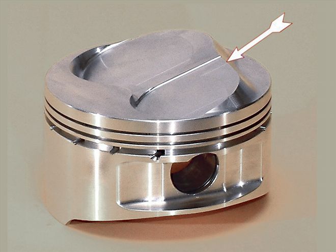
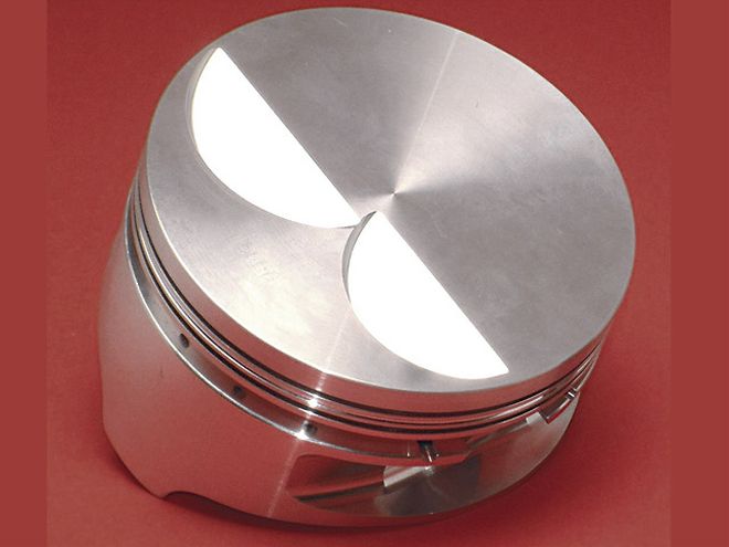 A flat-top piston such as the Ross here is about as user-friendly as it gets when it comes to producing an effective combustion chamber shape.
Since the piston crown constitutes a major portion of the combustion chamber, any discussion has to include the effects of such on the combustion process. When effective combustion is the goal, it pays not to lose sight of the fact that, up to a point, the faster the charge burns, the higher the compression ratio the cylinder will stand. As a point of empirical reference, chamber cavities between the piston and the cylinder head ranging from 60 to 120 thousandths appear most likely to encourage detonation. For the record, the noise heard when an engine is detonating is not, as is so often claimed, produced by two flame fronts colliding. In a so-called collision, flame fronts produce no noise.
Back on the subject of burn rates, we find that speeding up the combustion process can, to a certain extent, cut the possibility of detonation. It does so because the time the unburned charge is exposed to the radiated heat of the advancing flame front is reduced. This leads to the as yet un-burned charge being cooler. Also, a faster burn requires less timing advance. This means that there is less pressure rise on the upward stroke after the plug has fired and, equally important, this is normally accompanied by a reduction in peak pressure and temperature. Furthermore, because the burn takes place faster, the pressure rise and the average pressure on the downward stroke is higher. This leads directly to greater output.
It is vital to speed up combustion mixture motion and charge agitation. Generating random mixture motion within the overall swirl pattern just prior to ignition can be done by maximizing the quench action. On a small-block Chevy with a standard block and piston compression height, the piston is typically 25 thousandths down the bore. With a 40 thousandths gasket, this makes the static quench (squish) clearance 65 thousandths, which is a little on the wide side. By cutting the quench clearance, burn rate and combustion effectiveness are improved to the point where, although the engine gains compression, it is less likely to detonate even at the higher ratio involved.
 Here is a JE piston for an 18-degree head 12.5:1 NASCAR motor. The piston crown area indicated is cut back sufficiently so that the spark plug can start an effective flame propagation process.
What we have just discussed points toward one question--namely, just how close can the quench clearance get before contact problems arise? What comes next is one of those "don't try this at home" deals. When there are half a dozen dyno mules at hand, the sacrificial nature of testing for minimum head-to-block clearance is not quite as daunting. In an effort to quantify minimum clearance, I have run static piston/head clearances down to as little as 0.024 inch (24 thousandths) in a 3.5-inch stroke engine with production rods and close-fitting hypereutectic pistons. The pistons just kissed the head at about 7,000 rpm. With a four-inch stroke race crank, race rods, and 0.028-inch (28 thousandths) clearance, the forged pistons, at 0.004 inch (4 thousandths) clearance, just kissed the head at about 7,800 rpm.
As for power, an associate of mine ran tests with a nominally 450-hp small-block Chevy. These revealed that each 10 thousandths of quench reduction was worth approximately 7 hp. If you are building from scratch, make maximizing the quench your number-one priority toward achieving compression and minimizing detonation, regardless of what heads you may use.
Piston Crowns
Before buying pistons, understand that flat-top pistons, and small, compact combustion chambers are the racer's most user-friendly choices by a big margin. If a relatively high compression ratio is the intent, always go for all that is conveniently possible by minimizing quench clearance and cylinder head chamber volumes before making the move to raised-crown pistons. Although it seems a simple option toward achieving more compression, a raised-crown piston does not always deliver the goods. If compromised by the piston's intrusion into the chamber, a great deal of power can be lost. Personal experience has shown that it is possible to lose 100 hp because of a poor combination of piston crown and combustion chamber. Unless you have time to burn on a dyno developing a piston crown form that works, stick to crowns no more than about 0.100-inch (100 thousandths) high.
As compression goes up, combustion speed is increased. Assuming no other changes, high-compression cylinders deliver optimal results on less advance than low-compression ones. The amount of ignition advance needed to make maximum output is often a measure of how effectively the combustion chamber is burning the charge. Bear in mind that any pressure rise on the compression side of the stroke (due to ignition advance) is negative power. The only reason the plug is fired before TDC is to compensate for ignition delay. This, with highly leaded fuels, can be up to 10 degrees longer than with unleaded. Almost regardless of what is done, we can say, initially at least, the charge is not burning as fast as we may like it to. The proof of a good combustion chamber is that it needs little advance to deliver maximum power. Ideally, if we could burn all the charge between about 5 degrees BTDC to about 20 or so after, there would be little if any gains left to be had in this department. Nevertheless, this is almost never the case.
Shape & Surface Finish
Covering this rule will be the quickest of the bunch. Any time the surface finish is fine enough that the highest protrusions don't stick through the general boundary layer thickness, then improvements on the finish have little effect on air flow. Be careful about polishing surfaces that are likely to carry wet fuel flow. A rougher (like a quality cast finish) can actually be an advantage. The bottom line is that shape is 98 percent of the deal and a shiny finish, at best, 2 percent.