We've all heard the popular acronyms, "found on road dead" or "fix or repair daily" that we use to poke fun at fellow enthusiasts who chose to build brand-X iron. Here at Mopar Muscle though, we are firm believers in the adage that Mopar stands for massively over-powered and raced. And if the Ford or Chevy guys want to debate that saying we'll be happy to meet them at the track; we're there every weekend.
So when Rich Yates of Leesburg, Florida, approached us with a plan to build a 572ci race wedge for his '71 Duster, we were immediately interested. Even more exciting for us was the fact that Rich wanted to utilize some trick components, such as Jesel rocker arms and an adjustable Jesel beltdrive timing system. The engine will also be topped with a Hensley manufactured sheetmetal tunnel-ram intake with twin Dominator carburetors, so the potential for power really caught our attention. In fact, our only hesitation was the feeling we may be able to tweak more power from this engine than the Duster's back-halved chassis could take. But hey, too much power is a good thing, right? We can always make chassis improvements down the road if we need to, so we decided to build as much power as we could with this engine and leave the chassis adjustments for later.
Any time you're contemplating an engine build you need to clearly define your goals. Rich races his Duster in the Super-Pro bracket class every weekend, sometimes even twice in a weekend, so endurance is a key component to this build. Also, being the faster car in a bracket race not only provides the advantage of being the second car with the chance to red light (the first red light loses), but also ensures that once a slower car is caught at the top end of the track, you'll have the power to peddle the car and stay ahead of your opponent to win the race. For this reason, we want to build as much power as we can from this combination without sacrificing dependability. Rich's previous engine was a 540ci wedge that made close to 900 hp, so we figure the extra cubic inches and flow of the Indy 572-13 heads should easily get us into the mid- to upper-900hp range. With this kind of power and a ton of torque, the only problem we foresee is traction related. Our Duster has been back-halved to make room for 16-inch-wide slicks, and stiffened with a full cage and frame connectors, but traction still may be an issue for this combination. Our only saving grace is the adjustment capability offered by our four-link rear suspension, wheelie bar, and double adjustable front and rear shocks. On a marginal track we may still have problems hooking up, but hey, that's a byproduct of the power this 572 will be making, so in the name of low elapsed times, we'll deal with it.
The 572ci motor has become a staple for drag racers who utilize all brands of equipment, and Mopar is no exception. The 4.5-inch bore and 4.5-inch stroke make for a powerful and durable combination, which is ideal for a fast and consistent bracket car. Building a 572ci Mopar big-block, however, is not a task that can be accomplished with factory parts. None of Chrysler's production big-blocks have the bore spacing to accommodate the 4.5-inch bores necessary for this build nor will a factory block withstand the power that a 572 will make, so a Mopar Performance Siamese bore mega-block was chosen for this build. A Callies 4.5-inch stroke crankshaft will be used along with BME 7.125-inch aluminum connecting rods connected to Ross-forged, flat-top pistons. The deck height will be as close to the top of the cylinder as possible, netting a final compression ratio close to 14.07:1(see sidebar on calculating compression ratio). This engine will be spinning at upwards of 7,500 rpm so accurately balancing the rotating assembly is mandatory. Kevin Willis of Auto Performance Engines in Auburndale, Florida, handled the balancing job for us, as well as performing the remainder of the machine work for this project. Remember that accurate machining is key to the life of any high-performance engine, whether it is a street or strip engine. This combination utilizes some rather pricey parts, so we'll spend the extra money for an accurate balance job rather than risk destroying our high-dollar engine due to an imbalance issue.
While our parts were at Auto Performance Engines, we also had Kevin bore and hone our block with torque plates, as well as cut our new Indy heads for O-rings. If you're not familiar with sealing the combustion chambers utilizing the O-ring method, the concept is pretty easy to understand. A small groove is cut into both the block and the cylinder head around each combustion chamber where the head gasket seals. A piece of stainless steel aviation safety wire is then placed into one of the grooves (usually the one in the head) to form the O-ring. The other groove is called the receiver groove and gives the head gasket somewhere to go when the head is torqued onto the block. This method requires a copper head gasket and will virtually eliminate any leakage from the combustion chamber around the head gasket sealing surface. This method works exceptionally well in engines where cylinder pressures are much higher than normal, such as high-compression, nitrous-oxide, turbo, and supercharged applications. Our engine will be normally aspirated, but is relatively high compression so we'll see a benefit from the O-rings, but, more importantly, we will have the ability to add nitrous oxide at a later time without worrying about blowing a head gasket.
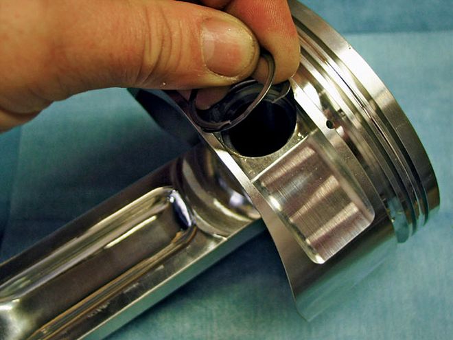 Our forged Ross pistons incorporate full floating wrist pins, which reduce friction and aid in pin oiling. Rather than being pressed into the connecting rod, these pins are retained by installing spiral locks in grooves cut into the piston.
When it came for cylinder head selection for this engine, there really weren't many choices. We considered keeping the Indy 440-1 heads that topped our 540-inch engine, but felt they would limit the power output of this size motor. Brodix's original B-1 cylinder heads also crossed our minds, but our tunnel-ram was designed for Indy heads, and a redesign or new intake would be cost prohibitive and just didn't make sense. The logical choice for this engine turned out to be Indy's 572-13 cylinder heads. The Indy 572-13 CNC units offer an intake runner volume of 385cc's, which is nearly ideal for our rather large displacement engine in a high-rpm drag racing application. Also beneficial to power output are the large 2.30-inch intake and 1.88-inch exhaust valves in these cylinder heads. The 78cc combustion chambers and flow numbers in the 400-cfm range add up to a cylinder head that will not only feed our 572, but will also support a larger displacement engine if we choose to upgrade even farther in the future. Always consider what the future will hold for your vehicle when making your parts selections. We could have used the 440-1 heads we already had for this build and would have made respectable power, maybe even as much as with the 572-13 heads, but Rich mentioned upgrading to a whopping 622-inch engine within the year, so the 572 heads were the logical choice. These heads don't come without baggage, however, as costly Jesel rocker arms and an external, spray bar oiling system for the upper valvetrain must be utilized to make them work. The good news is that even though you must pay a premium, the Jesels are virtually indestructible and will hold accurate valve timing for the life of the engine.
Camshaft selection for a race engine such as this should not be taken lightly. Improper camshaft choice or improper camshaft timing can lead to unimpressive results, so we did our research carefully and consulted both Indy Cylinder Head and Hensley Performance before making our choice. A solid roller cam would be mandatory for this high-rpm race engine so that part of the decision was easy, however, deciding on the specifics required some thought. Drag racing engines such as this only operate at a relatively high rpm when making a pass down the track. This car has a 5,500-rpm stall converter and is launched at 4,600 rpm, so choosing a cam that makes power below 4,500 rpm would limit top-end power and makes no sense. Our shift points will be in the area of 7,500 rpm, and we'll be spinning around 8,000 rpm when going through the traps in the quarter-mile, so again, a camshaft that makes good top-end power is mandatory. Large displacement engines require wide lobe separation for proper high-rpm operation; ideally, we'd be looking for a camshaft with 112 degrees of lobe separation. Our research led us to a custom-grind solid roller camshaft manufactured by Cam Motion. This cam features the 112-degree lobe separation we were after and offers lift numbers of .720 on the intake and .676 on the exhaust. Duration at .050-inch valve lift is 284-degrees intake and 303 degrees on the exhaust side. The long exhaust duration combined with some 70 degrees of valve overlap will greatly aid in cylinder scavenging and should provide good peak power and broad power and torque curves, which will be ideal for a bracket engine. By using a Jesel beltdrive timing system we'll not only be able to degree this cam without mechanically installing bushings or offset keyways, we'll be able to experiment with cam timing at the track to optimize our combination.
Feeding this hungry powerplant will require more air and fuel than one carburetor can supply, so dual Holley 1,050-cfm Dominators will be our choice. Rather than using an off-the-shelf intake manifold, we had a custom, sheetmetal tunnel-ram built to optimize power in the rpm range we'll be using. Hensley Performance took every aspect of our combination into consideration to build an intake that would meet our specific needs. Certain production intakes would suffice, but to optimize power, a custom unit was the only way to go.
With all our parts on hand, the only thing left to do was assemble the engine, install it, and go to the track for some testing. Initially, we broke the engine in and made some partial passes to make sure everything was working properly before opening it up and seeing what it would do. What it did was shake the tires violently and head toward the right wall of the track, which made us realize our original traction concerns were becoming a reality. Traction was so bad, in fact, that we couldn't make a full pass during our first test session, so we took the car home for some chassis adjustments. After weighing the car at the four corners and slightly preloading the right rear tire, we were back at the track to make a string of 5.70-second eighth-mile passes in the Florida heat. The car still had a propensity to shake the tires through the top end of the track, but it went straight and was drivable, so we dealt with the tire shake. Speed in the eighth-mile was in the 127-mph range, indicating horsepower numbers well over 950. All in all, we were pleased with our testing and feel with minor chassis adjustments and good weather, low 5.60s or high 5.50s (8.70s in the quarter) will be attainable. That, my friends, is a good running Duster!
Calculating Compression Ratio
Contrary to popular belief, calculating compression ratio is not done by simply ordering pistons that are advertised to give a certain compression in your engine. Many factors determine compression ratio, and the piston is only one of them. To accurately calculate compression ratio mathematically, you need to determine the following six vital measurements of your engine.
Once the above dimensions are determined for your engine, a factor (constant) is determined, and then compression ratio is calculated by using the following formula:
(factor x deck height) + (factor x head gasket) + (factor x stroke) + head cc's*
(factor x deck height) + (factor x head gasket) + head cc's*
Factor is different for given bore sizes and is calculated as follows:
Bore x Bore x 12.87 = Factor
In our engine the bore is 4.5 inches, so the factor is as follows:
4.5 x 4.5 x 12.87 = 260.6175
Now we plug the factor and the other measurements into the formula to figure compression ratio. We'll use our engine as an example and do it in steps so that it's easy to follow along.
(260.6175 x .005) + (260.6175 x .040) + (260.6175 x 4.5) + 78
(260.6175 x .005) + (260.6175 x .040) + 78
1.3030 + 10.4247 + 1172.7787 + 78
1.3030 + 10.4247 + 78
1262.5064/89.7277 = 14.0704
Our final compression ratio is 14.07 to one.
*Piston dome height in cc's is subtracted from the head cc's for dome pistons; valve relief cc's are added to head cc's for calculations.