We recently caught the Ed Ducazau roadster pickup that won Best Hot Rod at the Oakland Roadster Show in 1960 as it was being displayed at the 2006 Grand National Roadster Show. As we were admiring the recent restoration by current owner Ray Allison, he pointed out a few things that were yet to be completed. The pinstriping had to be finished and some of the upholstery had not been completed to the '60 guise, but for the most part, it looked pretty good. Then it struck us; those chrome, three-wide, weed-eater headers were missing. They were, Ray admitted, but they were going to be done within a couple of weeks. Being our usual sneaky selves, we got the wheres and whens out of Ray and shot down to Dan Fink Metalworks the following week, where John West was just getting underway building those famous pipes. Check out what goes into building a custom set of weed-eater headers and then go get out your tools and make up a set for your hot rod!
The original headers on Ed's roadster pickup have seen better days. About all that's salvageable are the adapters that mount the headers to the Cadillac block. The tubes themselves are rusted beyond use, but John can use them as a template to make the new ones.
The first order of business is to make six new header flanges. These are cut from 3/8-inch steel and bolt to the existing adapters already mounted to the block.
Since the weed-eater-style headers have only a single 90-degree bend, John orders six pieces of pre-bent tubing with a fairly long radius 90. He then cuts the first tube, being careful to leave plenty of room on each end to trim to the exact length needed.
The shorter side of the tube is then mocked into place and trimmed until it fits up against the body where John wants it. The location of this first tube will determine that of the other two, so it's important to make sure the location is just right.
After trimming the tube down to where it looks like it might be close, John mocks it into position using wooden blocks. This allows him to check the height, angle, and relation of the first tube to the body.
With the tube in place, John marks a line along the bottom of the flange onto the tube. When it's slid out of the flange, the line tells him the depth of the tube in relation to the flange. Ideally, this line should be the same as the width of the flange-in this case, 3/8-inch. The first header tube is right on the money.
Here it is mocked in place and supported by the wooden blocks. John's happy with its position and is ready to move onto the second header tube.
Because the tire prevents the third tube from being kept long on the end, it needs to be trimmed down more precisely. Measuring from the center of the second flange to the center of the third flange gives John a good idea of how much to trim off the tube.
The second tube is done much the same way as the first, trimming each end until the relation between the two tubes are perfect. Wooden blocks are again used to keep it in place before it's tacked to the flange.
That amount is then translated to the long end of the tube and trimmed off on a bandsaw.
When the third tube is back in its place, it's obvious that the short end of the tube still needs to be trimmed.
Using the header flange as a guide, John eyeballs the measurement carefully and trims the tube to fit. Like the first two tubes, John also checks the depth of the tube in relation to the flange to make sure there is enough sufficient meat to get a good weld between the two pieces.
John uses a digital protractor to check the angle between the three tubes and, using wooden shims, sets them to within 1/2-degree of each other.
With the tubes mocked into position, the weed-eater headers are starting to take shape.
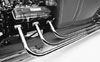
A quick overview of the engine shows how even the new headers are lining up with the old tubes on the passenger side.
Once the driver-side headers are fabricated and mocked into place, John moves onto the passenger side where he continues the same process. With both sides finished, it's time to make the rear support bracket for each side. To do so, John fabricates a bracket from angle iron that he pie-cut, bent, and welded back together. He then tapers the end with a grinder for a cleaner look.
John decided to put the clamp about a foot from the end of the headers. Using a C-clamp and a piece of aluminum, he clamps the bracket securely to the pipes. Notice the blocks of wood John installed between each tube to ensure that they are evenly spaced apart. The duct tape temporarily holds the three tubes together as one.
From the bottom, John tacks one nut to each pipe. These will allow the bracket to bolt directly to each pipe.
With the nuts tacked to the headers, the bracket is bolted into place. Then John drills two mounting holes through the bracket and into the frame.
Here's the bracket, temporarily installed, while John checks the fitment. If everything checks out fine, the nuts will be finish welded and all the hardware securely attached.
The bracket and header location checked out so John tacks everything together, including the header tubes and flanges. One more quick check and each tube is finish welded to its corresponding flange. By using separate flanges and making the bracket bolt to each tube, this enables the three tubes to be removed separately, making it easy to not only handle the headers, but to also allow the chrome shop to get between the three tubes without a problem.
To cut down on the harsh, open tone of the exhaust, John installs a 10-inch baffle in each of the tubes. They're held in by a set screw, which allows them to be easily removed for wide-open exhaust cruising.
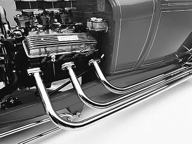
The finished product not only looks as good as the original did in 1960, but will hopefully outlast them as well.
Dan Fink Metalworks
17872 Metzler Ln.
Dept. SRM
Huntington Beach, CA 92647
(714) 841-6200
sales@hotrodproducts.com
www.hotrodproducts.com