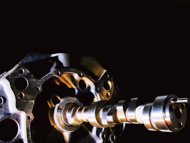
The most meaningful statement you can make about power production is that it all starts with cylinder heads that can flow large quantities of air. But having the greatest flowing heads counts for zero if the valves are not opened sufficiently or at the right time in relation to the crankshaft's rotation, and that very important function falls to the camshaft.
The problem is, if you are something of a novice at this engine business, just about everything to do with cams and valvetrains looks complex, and the truth is, it's that and more. If cam and valvetrain design at the top level is in your future, you had better thinkin terms of a Ph.D. in mechanical engineering. OK, so most of you are not looking to do that, but would like to understand cams and valvetrains sufficiently to make truly informed power-generating decisions. Being able to do so can easily mean choosing a cam for a typical street/strip small-block that will make 20-30 lb-ft and 20-30 hp more than your buddy who bought a generic grind out of a catalog solely on the basis of duration. (If it's bigger, it must be better, right?) If that 20-30 extra lb-ft and hp are important to you, then what you are about to read will give you the knowledge you need to get it.
Basics
The lowest denominators for a power-producing valvetrain are the lift and duration delivered to the valves. Like most statements that appear to sum things up elegantly in just a few words, this is a gross simplification, but we have to start somewhere. First, duration. This is the number of degrees the valve spends off the seat, or the degrees the lifter is above a specified lift. In catalogs, two numbers are commonly quoted. These come under the heading of advertised duration and duration at 0.050 inch (50 thousandths). The first of these is usually measured, for a hydraulic cam, at 0.006 inches and, for a solid cam, 0.020 inches (6 or 20 thousandths) of cam follower lift, while the second is at 0.050 inches (50 thousandths). A third duration figure, which is often confused with the advertised duration, is the duration at the lash point or, as it is also called, "off-the-seat" duration. Assuming a totally rigid valvetrain, the engine sees the last of these three.
Because the valve lash operates through a step-up rocker ratio, the lash between a solid lifter and the cam is usually smaller than the 0.020 inches used for the advertised duration, so the duration at the lash point is often longer by some 6-12 degrees. The exception here is that some of the older solid designs were designed to run 0.28-.030 inches lash. With this valve lash and the commonly used 1.5:1 ratio rocker, the lash point at the lifter was 0.020 inch--the same as the lifter rise used for quoting duration. This meant advertised duration and duration at the valve lash point were the same. At the other end of the scale, a modern tight-lash solid can be as much as 14 degrees longer than the advertised duration. For a hydraulic cam, lifter collapse is assumed to be about 0.006 inch, so the advertised duration is about the same as the duration at the valve. This makes duration comparisons between hydraulic cams much more realistic than between solids.
Now that we have defined the cam lobe's duration and lift, we can move on to looking at the cam's collective attributes; that is, the intake's relationship with the exhaust. The point here is that the engine's output will be optimized when the valves are open and closed at certain points in relation to the crank's rotation. To be able to specify what you want to your cam grinder, you need to understand the terminology involved. The cam attributes diagram shows what you need to know.
What dictates the cam's success in the quest for maximum area under the output curve along with highest peak torque and horsepower is not (as is so often assumed) the duration involved. The most important factor is actually the overlap and the Lobe Centerline Angle, often referred to as the LCA. I realize this may fly in the face of everything you have been told or have read before, but it's not that hard to see it must be so. Let's do one of those mental experiments to establish overlap as a highly influential criteria. First, and of prime importance to a street-driven performance machine, is manifold vacuum. Let's be clear that we are talking V-8s and single-plane manifolds here. As far as idle quality and vacuum are concerned, it degrades rapidly with increasing overlap. The reason it does so stems from the fact that a V-8 has an induction phase every 90 degrees. This means that when one piston is moving rapidly on its induction stroke (about 90 degrees down the bore) there is another piston stationary at the top of its stroke with the valves in the overlap position, i.e. both open.
With a typical 280-degree hydraulic cam, the valves (in the TDC overlap position) will be a little over an eighth inch off the seat. This means the piston moving rapidly down the bore in the middle of its induction stroke can draw through the intake manifold and right on through the overlapping valves to that cylinder's exhaust. The area it has to accomplish this in a typical V-8 is about equal to a 15/16-inch-diameter hole. On the other hand, the through-flow area via the carb's butterflies is only equal to a hole about 5/16 to 3/8 inch. It's not hard to see that, even in the case of a cam of only about 280 degrees with 64 degrees of overlap, the overlap acts like an unwanted hole nearly an inch in diameter in the intake manifold.
OK, so overlap, or at least too much of it, is not good for a street-driven engine. But let's not overlook that the actual amount of overlap is not the sole issue toward killing vacuum. If we replace the open plenum intake with a two-plane (180 degree) intake, in one fell swoop, we space out the induction pulses seen in each half of the manifold to 180 degrees instead of 90. This means there is no time when the one cylinder's intake can draw through the exhaust of another. As a result, the intake vacuum goes up by something in the order of 50 percent.
Overlap: How Much Is Too Much?
Assuming we are choosing a cam for a streetable engine, how much overlap can we use before it becomes a problem? The answer here is that it depends on the valve sizes in relation to the cylinder displacement. If the heads have small valves in relation to cylinder cubes, then the amount of overlap we can use is significantly more than the same cylinder with much larger valves. For instance, a 500-inch big-block Chevy can tolerate not only more overlap, but a much bigger cam because the cylinder heads are so under-valved for the displacement. A 350 small-block with a set of decent heads has a lot more valve-per-cube, so it does not need so much overlap to get the job done.
Now that we have covered the effect overlap has on street manners, it is time to look at its effect on power output. Let's make one thing clear here: Big (but not excessive) overlap is a prime key to big power numbers, but only if your exhaust system sucks. Literally. If you have ever heard that an engine needs a little backpressure, you might want to ask yourself why an engine would want an exhaust system that literally pushes exhaust back into the combustion chamber rather than sucking it out. The simple answer is, it doesn't. If a big-overlap, big-cammed engine has an exhaust system with any measurable backpressure, the price paid is a big drop in output.
Although the foregoing might be interesting info, it doesn't actually help you make a decision as to how much overlap your engine needs. Just in case you might ask, I use a one-off computer program that was 18 years in the making to do what we are doing here, but that is no help to you. So that you have something of a guide, I have made up the nearby chart. To make the most of this chart, you will need to take into account where, in terms of valve size per cube, your engine falls. For, say, a 302-inch engine with decent-sized valves, the overlap selected needs to be toward the short end (left side) of the segment that fits your application. If it's a typical 350-inch small-block, then choose something around the middle of the relevant segment. If the engine in question is a big-block or a really big-inch small-block (both of which are typically under-valved), then select the overlap toward the larger, righthand side of the relevant segment.
LCA Selection
With an overlap figure decided on, the next step is to determine the LCA. If maximum torque and power along with the biggest area under the curve is the target, then only one LCA will do the job, and it has to be the one the engine wants, not one you or someone else doing your guessing for you arbitrarily decides is the one needed.
To understand where I am going, let's take a look at a typical cam-buying scenario. A hot rodder calls up and asks for a hydraulic cam of, say, 290 degrees for his 350 small-block street driver. Now this is a fairly big cam and could involve a lot of overlap, possibly even too much for the application. What usually happens is the cam tech guy, recognizing that this cam may not be as well-mannered as the customer would like, recommends the cam be ground on a wider-than-optimal LCA. Widening the LCA reduces the overlap and tightening it increases overlap. To maintain sufficient idle and vacuum qualities, the cam tech recommends the cam be ground on, say, 112-degree LCA, which gives an overlap of 66 degrees. For a typical performance-headed 350, the optimal LCA is usually 108 degrees. Grinding the 290-degree cam, our guy is calling for on a 108 LCA results in 74 degrees of overlap. At first this does not sound like too much more, but the reality is it's the area of the overlap triangle that influences the situation, and the through-flow area of the overlap triangle goes up just about as the square of the overlap angle. This makes the 74-degree overlap a 26 percent increase, not the 12 percent you might have expected.
So spreading the LCA is a way of cutting the overlap while still retaining the duration. Unfortunately, nothing comes without a price. The downside of spreading the LCA to reduce overlap so a decent idle and vacuum are achieved has two major strikes against it. First, the piston comes further up the bore before the intake valve closes. At low speed this pushes the intake charge back into the intake manifold. Result: low-speed torque is reduced. But so long as it drives well, this may be OK if it helps top-end output. Let's investigate that. In-cylinder pressure measurements strongly indicate that there is an optimal balance between early opening of the intake (IOBTDC) and late closing (ICABDC). If the LCA is spread solely to preserve the idle and vacuum, the intake now not only opens too late, but also closes too late. Mapping intake, cylinder and exhaust pressures throughout the cycle indicates that getting the first half of the induction stroke right is of paramount importance toward making the second half optimal. In other words, if the first half of the stroke is not optimal, there are no means of redemption on the second half.
This forces us to the conclusion that for a given duration, there is only one optimal opening point and one closing. This, in turn, means, within a small window, only one LCA gives optimal results. If the LCA is spread to preserve the idle and vacuum, the price paid is reduced torque and hp. We should have gone to a shorter cam on the correct LCA, as it would have produced better results! The moral here is that if the cam had been selected on the basis of overlap and LCA first, then the duration would have been decided by these two factors, not some arbitrary decision on the part of the hot rodder. To arrive at the duration when the overlap and LCA are known, we take the overlap (in our example 66), divide by 2, add it to the LCA (108 + 33), then double it (141 x 2 = 282). That's the duration needed to satisfy the overlap and LCA requirements, and I will bet arriving at the required cam this way is a whole lot different (and far more accurate) than you have been told in the past.
How Do You Know What LCA Is Needed?
Now we come to what would normally be a real stumbling block. Exactly what LCA does an engine need for optimal results? The bottom line is that it's all related to how big a cylinder the intake valve has to feed. The bigger the cylinder in relation to the valve, the tighter the LCA needs to be, and vice versa. That is the main factor. Additionally, but to a lesser extent, we also find that as the compression ratio goes up, the optimal LCA gets wider. This is good because it means smaller valve cutouts in the pistons. For an engine in the 9 to 11:1 CR range, the LCA selection chart will, 99 times out of 100, deliver accurate results. For each ratio above 11:1, it pays to spread the LCA about 1 degree for every two ratios of compression increase.
Duration & Lift: Its Effect On Output
Now that we are over the duration hurdle and can look at it in a more realistic fashion, let's look at exactly what it delivers. Assuming the compression ratio remains constant, longer duration just moves the torque curve up the rpm range. Peak torque itself usually only increases a minor amount. The additional hp comes from the fact that the torque delivered happens at a higher rpm and power is directly proportional to torque times rpm. The graph of duration versus output shows what typically happens as the duration increases while all other factors are held constant. Although it looks like a good before-and-after test showing the longer cam's value, this test does in fact favor the shorter cam. Because the intake valve closes sooner after passing BDC, the running ratio, or dynamic compression ratio, with a shorter cam is higher. If the compression ratio with the longer cam is raised so that the same cranking pressure as the shorter cam is seen, we find that much of the low-speed torque loss is recovered. In addition to this, the longer cam will deliver a much better top end when an appropriate compression increase is made. This is an important factor, so don't overlook it. If you don't feel inclined to run a compression to match a longer cam's requirement, then stick with a shorter one, as it will produce better results.
For most V-8s with reasonable heads, the ability to raise low-speed torque with compression increases holds good to about 285-290 degrees (at lash point) of cam duration. After that, low-speed torque will drop off faster than further compression increases can recover it. A cylinder's breathing ability is not only dependent on the duration of valve opening, but also the amount of valve lift involved. The type of heads typically used on domestic V-8s are much more responsive to lift than, say, a four-valve engine.
There are two reasons for this. The first is that all two-valve V-8s are under-valved for the cubes those valves have to feed. Secondly, heads with a predominantly parallel valve design go through three phases of flow efficiency. The first, right off the seat, is a high-efficiency regime. As the valve lifts through the 0.100 inch (100 thousandths) to about 0.500 inch (500 thousandths), efficiency drops off considerably. Once the valve lift goes over a point equal to a lift of about a quarter of the valve's diameter, the flow efficiency starts to pick back up. The reason for this is that intake valve's shrouding starts to diminish because the valve is sufficiently far enough out of the seat's sphere of influence. For this reason, most of the V-8s we work with will benefit from valve-lift values equal to about 0.3 to 0.35 times the diameter of the intake valve. For a typical 2.02-inch intake, this would mean a lift of at least 0.6 inch (600 thousandths) to as much as 0.7 inch (700 thousandths). Achieving this with a short cam is something of a challenge, so going for all the lift possible consistent with reliability is worthwhile.
While doing a bunch of cam testing for Harvey Crane some years ago, I ran a test to get some kind of idea of the relative importance of duration versus lift. The results were interesting, as the nearby graph shows. The hydraulic flat-tappet cams used were 252 and 260 degrees duration. With a 1.5 rocker, the 260 cam delivered 0.44 (440 thousandths) lift while the 252 cam with a 1.7 rocker went to 0.48 (480 thousandths) lift. The intake valve lift at TDC was 0.070 for the 252 cam, and for the 260 cam and 1.5 ratio rocker, 0.073 (73 thousandths). As can be seen from the results, the peak power output from each combination was near identical, but the shorter-duration, high-lift combo made power at less rpm because it produced more torque, especially at low speed.
Lifters
Now that we have worked our way through what an engine would like in terms of optimal valve events, we can move on to look at the hardware choices open to us to achieve such. The first component on our list is lifters. Our options are covered by four types of lifters, also know as tappets. These can be had in either flat or roller form, and each of these comes in a hydraulic or solid design.
A flat lifter is, in reality, not flat on its working face, and would quickly fail if it was. The lifter's face is actually crowned with a 60- to 100-inch radius. The cam lobe itself is tapered. This, in conjunction with an offset of the lifter over the cam lobe, causes the lifter to rotate. This means it is not a simple rubbing action between lifter and lobe, but a semirolling motion. Without the correct rotation, the lifter will have a short life. The contact patch between the cam form and lifter is one of the highest-stressed areas in an engine. If heavy springs are going to be installed, it pays to use armor-faced lifters such as those sold by COMP Cams. Flat lifters are inexpensive and they can get the valve off the seat really fast. What they don't do quite as well as a roller is build lifter velocity or deal with super heavy springs. The amount of velocity that can be imparted to a flat lifter is dependant on the lifter diameter. The wider it is, the faster it travels. Because a flat lifter can initially accelerate faster than a roller, we find that with cams under about 270 to 278 degrees of off-the-seat duration, a flat tappet can produce as much or more area under the curve. It also used to be claimed that a flat lifter design was substantially inferior to a roller lifter in the friction department. Though this was, to an extent, correct 20 years ago, we find that new super oils have eaten substantially into whatever friction reduction advantage the roller may have had over a flat lifter.
If maximizing output is the goal and the budget extends to the higher price of a roller lifter cam, then, for anything over about 275 degrees, the roller is potentially a superior power producer. Where it scores is the velocity it can impart to the lifter is higher than a flat lifter. If it has enough duration to get up to speed, then the lifter can be pushed higher. As we have already seen, valve lift with a two-valve engine is an important factor, and a roller can deliver in this area.
Once a flat or roller lifter decision has been made, the next question is, solid or hydraulic? Of the two, hydraulic is the most popular for street use as it is quiet and virtually service-free. The hydraulic innards adjust the working length of the lifter such that it takes out all the lash and no more.
You may have heard the term "anti-pump-up lifters." These are intended to fix a problem that can occur toward the top 25 percent of the engine's rpm range. What happens is that the spring starts to lose full control of the valvetrain and separation between various components takes place. This, as far as the lifter is concerned, looks like lash, so the lifter does it's job and takes it up. When the valve now tries to close, the lifter, which is now a little too long, holds the valve off its seat and heavy-duty power loss takes place. For many years, the accepted fix for this was an anti-pump-up lifter, which was a much leakier, faster-collapsing lifter that allowed the valve to physically close unimpeded. But it also collapses easier and consequently cuts valve lift. The real fix is a spring with better control. That's a serious topic we will talk about later.If valvetrain noise is of little or no concern, then a solid cam is the way to go, as there are no worries about hydraulic lifter collapse.
Before moving on to pushrods, some vital info about flat-lifter cams could save you a lot of hassle. Because the surface loading is so high, flat lifters require a break-in procedure that needs to be carried out conscientiously. Never re-use lifters; always use new ones. When installing, generously lube the cam profiles and the lifter faces with the special cam lube supplied with the cam. Make sure the lifters rotate freely.
On start-up, idle the engine at 2,000 rpm for 20 minutes. Do not allow the engine to idle slowly until initial break-in is completed. When very aggressive race profiles are used, the break-in should be done on lighter springs or with low-lift break-in rockers.
Pushrods
A pushrod looks like a simple item. Just make it stiff and light and you are home dry, or at least it would seem so. Sure, low weight and stiffness are key ingredients, but there is another important factor related to pushrod manufacture. Its ability to suppress vibrations. If it can do well here, it acts as a simple damper between the lifter and rocker, rather than a spring. The modern aftermarket pushrod has countless hours of spin-testing to optimize the balance between low mass, stiffness and damping. Doing so ensures a more optimal valve motion. This ultimately translates into additional output. Because a pushrod can influence the valve's motion from as low as the middle of the speed range, additional output can be seen from there on up if it is canceling spurious motion at the valve. Since it is difficult to know for sure that your valve springs are dynamically perfectly behaved, it pays to use a good aftermarket pushrod as a little insurance. But there is more to buying pushrods than just shelling out for a good brand.
When changes to the valvetrain are made and maybe the block and heads have been milled, we can find that the pushrod/rocker/valve stem geometry with a stock length pushrod is anything but correct. The technique here is to use an adjustable pushrod and adjust its length until the roller or rocker tip sweeps out a patch that is centralized on the valve stem. Also, with high lobe lift cams, you should check that the ball end of the pushrod is not moving through an arc larger than the ball will accommodate. If it does, than check your cam supplier's catalog as there are pushrods with tips to allow greater angularity.
Rockers
Rockers not only operate the valves, but they are also extremely useful as a valvetrain tuning aid. Most of the V-8s we deal with have stamped-steel rockers. These are cheap, but if used for lifting the valves much more than about 0.500 (500 thousandths) will cause accelerated guide wear. If the cam is a short, flat-lifter design for a small-block Chevy, you may, if the budget is tight, want to consider Crane's 1.6:1 ratio items. The stock rocker is supposed to be 1.5:1, but rarely comes higher than about 1.45:1. If the budget is a little above basic replacement level, then both Crane and COMP have some roller-tipped rockers that still utilize the stud-mounted ball pivot.
For a little more money, you can get a fully rollerized aluminum race-style rocker. Other than being able to get them for most applications in a variety of ratios, these rockers have the advantage of lower friction and the ability to accommodate ultra-high valve lift.
For the most part, aluminum makes a good rocker material because it has an inherent internal damping capability. On the debit side is that aluminum fatigues, so when heavy race-type springs are used, the rockers will need to be replaced at regular intervals. Stainless steel rockers such as those produced by Comp Cams and Crower have an almost infinite life.
Another option if you're planning on an up-scale engine is to convert from stud-mounted rockers to shaft-mounted ones. These are not cheap, but they do provide the best in valvetrain control.
If you have a better understanding of rocker geometry, you will almost certainly have a power advantage over a less-informed racer. The principle point of a rocker is that it steps up the motion delivered to the valve by the lifter. This is known as the "rocker ratio" and is usually the ratio of the radius of the valve side of the rocker divided by the radius of the pushrod side. If the centerline of the points A, B and C as per the drawing on p. 76 all fall on a straight line, the rocker ratio will remain constant throughout the rise and fall of the lifter. This is OK, but not necessarily the best situation for maximum output. In any undervalved engine, and that's pretty much all two-valve engines, greater output can be had by lifting the intake valves as fast as possible off the seat. The faster the intake is lifted, the less cam duration is required to make peak power. A shorter cam with a faster-opening rocker, as we discussed earlier, will make more torque while still making the peak power of a longer-duration, lower-lifting valvetrain.
A question often asked is how high a rocker ratio is best. If you consider that the purpose of a valvetrain is to move valves, not pushrods and lifters, then it becomes apparent that the higher the ratio, the better within the mechanical constraints imposed by the materials involved. Current maxed-out valvetrains are lifting the valves to about an inch and running to about 10,000 rpm. All this is being done with rockers in the 1.9 to 2.1:1 range.
Stepping up the rocker ratio is often a good way to increase output with no more than a simple bolt-on mod. Higher-ratio rockers can spread the engine's required LCA. This means that if the existing cam has too wide an LCA, as is so often the case, bolting on a set of high-ratio rockers can pay a handsome dividend. On the other hand, if the LCA was such that the overlap triangle was optimum, installing a higher-ratio set of rockers can drop output rather than increase it. My own tests have indicated, within the ratio range of 1.5 to about 1.9:1, that for every 0.1 ratio increase on the intake, the LCA needs to be spread by 0.75 to 1 degree.
As for the exhaust, we find that it is relatively insensitive to valve acceleration but is sensitive to duration. For this reason the rocker ratio used on the exhaust is best kept about 0.1 to 0.2 of a ratio lower than the intake ratio.
As for power increases as a bolt-on deal, for something like a small-block Chevy or Ford, experience shows you can reasonably expect to see results similar to or better than shown in the graph below.
Retainers & Keepers
Retainers and keepers (also known as locks) have a simple job, but they sure take a beating doing it. When selecting retainers, bear in mind they must fit snugly on the springs with which they are to be used. Also, they need to be as light as possible, consistent with surviving. Valves are made with various groove styles, the most common being the square lock and radius lock. The grooves in the valves and the step in the keepers are not there to act as retention for the valve and spring assembly. It is the taper in the retainer driving the keeper to a super-clamping force on the valve stem that, for the most part, holds everything in place.
Retainers and keepers come in two different angles, these being 7 and 10 degrees. Seven-degree retainer/keeper combinations are the norm and are used almost universally by the OEM. These work just fine until spring forces escalate to the levels required to run big valve lifts and very high rpm. Under such circumstances the keepers literally bind themselves into the retainers making a teardown really difficult. By going to a 10-degree angle, the clamping force of the keeper on the valve stem is reduced, but teardown is far easier.
Springs
The most important aspect of a high-speed valvetrain is the spring. It is entirely true to say that the valvetrain is, at best, only as good as the spring. What we want from a spring is near infinite fatigue life, low mass and a high delivered force. Striving for these mechanical virtues produces a long-life spring with a high, natural vibration frequency, or to give it its technical term, resonant frequency. The higher the resonant frequency, the less likely the spring is to go into surge. Without steps to abate it, surge can occur at a number of points as rpm increases. Basically, surge causes the valvetrain to lose some or all control of the valve motion. The result is loss of output at whatever rpm it occurs.
Interference fits between two oppositely wound springs, as in a typical dual spring or a dual spring and flat wound damper, are methods used to damp spring surge. When selecting a spring, consider the delivered force versus the weight of the spring. An 80-gram spring that delivers 110 lbs on the seat and 300 over the nose will control the valvetrain far better than one with the same poundage but weighing in at 110 grams.
Dual and damped high-performance springs have been the valvetrain designer's number-one means of getting the job done for better than half a century. By about 20 years ago, most of the development potential of the dual (or triple) parallel-wound springs had been used. Steel alloys were not going to get much better without some big breakthrough, and titanium, being stiff and light, was a viable alternative, but was expensive and difficult to work.
With gains from conventional materials at a near standstill, the other option spring specialists had was to look at spring design to see if there was a better alternative to the parallel-wound conventional spring. Turns out there was, and during the mid 1980s GM began research on the application of a design known as the "beehive" spring. As its name suggests, this spring is wound in a beehive form. With each coil getting progressively smaller, this spring has no clear-cut resonant frequency. As soon as it starts to resonate at a particular frequency, the resonant frequency changes. Result: Spring surge is, in almost all applications, reduced to levels bordering on insignificant.
The beauty of the beehive spring is that it uses its delivered force far more effectively than a conventional parallel-wound spring. It needs far less of its delivered force to control its own motion, so this leaves more to control the valvetrain. This means less overall valve-spring loads while delivering more rpm. Our spin tests on a street roller cam showed an rpm increase from 5,950 to 6,900. This was achieved with a beehive spring (COMP Cams PN 26918) with 8 lbs less on the seat and 20 less over the nose than its parallel-wound counterpart. Because of the propensity of hydraulic roller lifters to collapse easier than their flat counterparts, beehive springs are well-suited to hydraulic rollers. Reduced loads and better control pay off in terms of added output and rpm. The two occasions tests were run, both in small-block Fords (302 and 392), showed about a 6hp gain in each, but considering just the change in peak hp is only a small part of the story. Take a look at the graph showing the before and after tests of the beehive spring, p. 78. What you see here is a valvetrain that retains control to significantly higher rpm. The regular spring, in spite of being stronger, hit valvetrain crash at a shade over 6,000 rpm, but it was progressively losing control (or collapsing the lifter or a combination of both) at 5,700 rpm. The beehive spring kept it all together up to about 6,600, although power figures were only recorded to 6,400. At 6,000 rpm the beehive's ability to deliver superior control netted an increase of some 65 hp.
Valves and Mass
For the type of valvetrains we are looking at, the mass of the valve is as significant as that of the spring/retainer combination. From the tech point of view there are no dark issues to comprehend. The golden rule is the lighter the better. With lighter valves the amount of acceleration imparted to the valve can be increased either by a more aggressive cam profile or a higher lift rocker. The faster the intake can be opened and closed the greater the engine's output potential. For the exhaust, things are somewhat different in as much as a fast-opening exhaust valve action is not required. Indeed, it is possible to open the exhaust valve too fast and actually reduce output. Costwise, this can actually play into our hands.
Most of us use stainless valves because they are relatively inexpensive. Top-of-the-line lightweight valves are made of titanium, and they cost something bordering an arm and a leg. Fortunately, Ferrea makes a stainless valve that is better than a halfway house at less than a halfway house price. These are their hollow-stem valves. The nearby Spintron tests show where each type of valve lies in the grand scheme of things.
Cost is an ever-present barrier, but there are ways to maximize a valvetrain's ability to run the best rpm possible per valve dollar spent. By juggling valve types between intake and exhaust, we can make the most of our valve budget dollars. Remember, only the intake has to be opened fast. Because the exhaust valve is smaller and consequently lighter and is usually run with a lower-lift rocker, we find that we can use a hollow-stem intake and a less expensive solid-stem exhaust. The same move can be applied if you can go upscale on cost. A combination of a titanium intake with a hollow-stem stainless exhaust works just about as well as having both valves of titanium. Not only is this less costly, but for a long distance engine it is actually more durable.
Next Month...
If you absorbed all this, you should be well along the road to being a cam guru. What we have not touched on, however, is physically timing-in cams and the consequences of advancing and retarding the cam. This will also be a vital part of your cam and valvetrain education, but it warrants a feature all its own. Check PHR next month for the rest of the story.
Spring Surge: What Is It?
Spring surge is when the spring can no longer fully control its own mass. This situation is caused by the spring being excited by a force that coincides with the spring's natural vibration frequency. Imagine a hammer striking the end of a spring. The impact (not unlike that of a valvetrain about to open a valve) will take time (be it very short) to travel down the spring. The effect of the impact is to close up the space of the top coil and the one immediately below it. This closing of the coils passes down the length of the spring until it reaches the bottom coil. There it is reflected and returns to the top. The point to note is that as it reaches the spring seat, the poundage the spring delivers is substantially reduced. In severe cases the lower coil of the spring can actually jump off the spring seat. When a spring experiences this sort of internal motion, it is in no way able to control the valvetrain.
Take The Easy Way Out
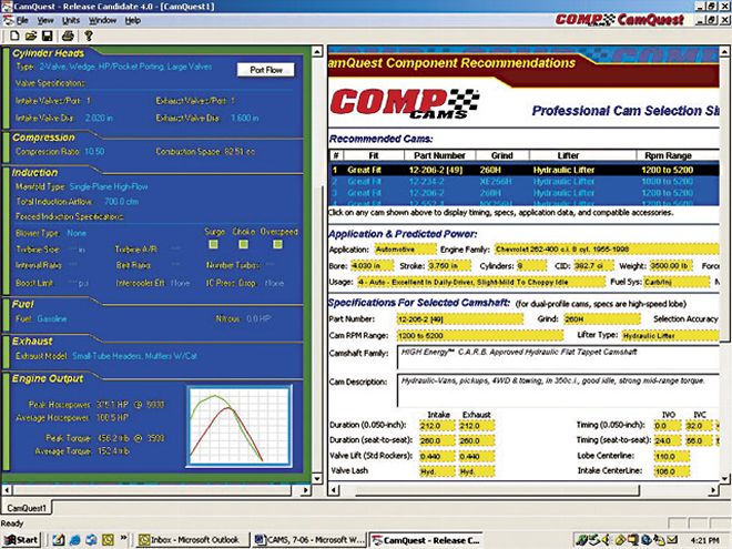
Stumped by Vizard's verbosity? Call up COMP Cams and ask for the CamQuest6 cam-selection software--it costs 10 bucks. It works on any PC with Windows 95 or newer. It's just like the award-winning DynoSim engine simulation software, only it's a lot cheaper. After installing the program, just fill in the prompts for your engine specs on the left side of the screen. You'll be asked your engine type, induction, engine size, planned useage, cylinder head type, exhaust type and a few other questions. After a few nano-seconds, a list of camshaft profiles pops up on the right side. As you scroll through the list of computer-selected cams, the dyno graph on the lower left of your screen changes to reflect the power output of that cam combination. The best part about CamQuest6 is that the program gives you exact COMP Cams part numbers. Just pick the power curve you want, dial 800-999-0853, and give 'em the part number listed on the CamQuest6 screen. You can even tell them you heard about CamQuest6 from PHR and they'll give you your 10 bucks back on your cam order. And just how accurate is CamQuest6? We plugged in the specs for our smog-legal 383 small-block from Project g/28, and got a power curve that looked so close to our real dyno numbers that it nearly scared us.--Johnny Hunkins