The mechanical contrivance most responsible for converting the rising pressure from the combustion of air and fuel is the crankshaft, along with the rods and pistons contained within the block. What you choose to use here can make the difference between building an indifferent and potentially unreliable engine and building a real powerhouse. With that in mind, let's start the ball rolling at the centerline of the crank and work our way out from there.
Crank Know-How
Cranks are essentially available in three grades: cast, forged, and billet. That is also about the order of their cost. Many production vehicles have cast-iron cranks. These won't take either the outright power or abuse a forged one will, but they are plenty strong enough for even a decent factory street performer. Also, cast iron has very good wear properties so the life of a cast crank can be very good. A forged crank is a step up the ladder and, for more money, provides greater strength.
Although factory cranks are usually lesser grade steels, the steels most commonly used in aftermarket cranks are 4130 and 4340. Depending on the cost of the crank, these can be had with surface hardening which gives a very good wear life. Last on the list are billet cranks. These are made from a block of steel because there is no appropriate forging available from which to machine the desired design of crank. Needless to say, they can be very expensive.
If an engine is stripped for a re-build, it is a cost-effective plan to consider all your crank options. These days the availability of quality cast steel cranks makes installing the original used crank only barley less money. Cast steel, which can be looked upon as a hybrid between forged steel and cast iron, allows far tougher cranks to be produced at near the cost of regular cast iron ones. Although it still falls short of a forged crank's ultimate strength, it is an extremely cost-effective halfway house between a regular OEM cast and an aftermarket forged crank. Also, cast steel opens the door to reliable low-cost stroker cranks. Because they can be so inexpensive, you can figure that a new quality stroker crank can be as little as about $75-$125 more than getting your existing, and almost certainly fatigued, crank re-ground.
Reliability
So how good are these cast steel cranks? Assuming a reputable company like SCAT, who also supplies an OEM market that calls for tight quality control, we find they are extremely good for all usage up to moderate race levels. Personal experience over a 15-year period with small-block engines up to 580 hp has shown none have failed or worn out. A road-race engine built in 1999 now has over 5,000 race miles on it at a power level of some 500 hp, and the last teardown revealed that it, and the bearings, was still in near-perfect condition. Although potential reliability is built into a good stroker crank, it should not be taken for granted. Any time the stroke is increased, there is an increase in inertial loads. These and other associated factors need to be taken care of in an appropriate manner. Let's look at reciprocating loads first.
If the stroke is increased by 10 percent, the reciprocating loads will, at any given rpm, go up by 10 percent. Although reciprocating loads are proportional to the mass involved, they go up with the square of the rpm. What this means is that if the engine is turned at 10 percent higher rpm, the reciprocating forces go up by 21 percent (1.1x 1.1 = 1.21). To offset the inevitable combination of the greater stroke and the desire for more rpm, we need to look for a lighter-than-stock piston. Checking through various manufactures' catalogs looking for pistons that are toward the lighter side is time well spent. Here, ROSS, Mahle, JE and KB are worthwhile starting points. If the piston is offered with a lightweight pin upgrade, then, budget allowing, this is well worth considering.
Piston Selection
When buying pistons you will be presented with some material options that you need to know about. Firstly, regular cast pistons are the cheapest option. To make them harder, the aluminum used for regular replacement and earlier-style OEM cast pistons is alloyed with silicon (which is in essence melted sand). The silicon content makes the piston harder and more wear-resistant, but set against this is the increased brittleness. This makes it the least desirable of the type of pistons available to us for performance use. Next on the list is a hypereutectic piston. These started gaining popularity for lower-cost performance applications in Europe back in the mid '70s. In the early '80s, Sealed Power started experimenting with hypereutectic pistons and subsequently introduced a successful line of them. This was followed by Silovolite, who introduced the Keith Black (KB) signature series performance-oriented hypereutectic piston.
Although the term "hypereutectic" is commonly used, it is often not understood. For "hyper - eutectic," read "super - saturated." An alloy that is at the point where no more of the principle alloying element will dissolve in the parent metal is said to be at the eutectic or saturated point.
A regular cast piston can have up to about 10 percent to 11 percent silicon in it. This is about the eutectic point. Any more silicone will put the alloy into the hypereutectic range and as a result, form free crystals of silicon. Normally, these free silicon crystals will cause a reduction in strength, but with suitable heat treatment a hypereutectic alloy can be toughened up to a level above that of a regular cast piston.
In terms of outright strength and toughness, a hypereutectic piston still falls short of a forged piston, but not by as much as the difference in material strength might suggest. The reason for this is that the process of casting a piston, as opposed to forging it, allows the material to be put right where it is needed to support the stresses involved. With a forged piston, the underside has to be designed such that the forging punch can be extracted after the piston blank is formed. It is only by extensive (and costly) post forging machining that a forged piston can rival a cast piston in terms of lightness. By using up some of this low weight advantage by incorporating extra material at strategic points, the cast hypereutectic piston, in practice, comes out looking a lot stouter.
As far as materials for forged pistons are concerned, there are three of note. Probably the most widely used, because it is also used for OE applications, is the Federal Mogul (TRW/Sealed Power division) VMS75 alloy. This was developed probably as far back as the 1960s as a good all-around high-performance alloy for pistons. Most of the rest of the piston industry uses one or both of two alloys, these being 2618 and 4032. The 2618 is most commonly used for outright race pistons as toughness at elevated temperatures (up to about 575° F) is good. On the down side, it lacks the hardness of 4032, which is a high-silicon alloy. Though slightly less tough, the 4032 alloy is a better material for high performance street and race use and would, in most cases, be the alloy of choice for such. At the end of the day, consulting your piston manufacturers about the choice is the way to go, as they are the experts here.
Let's now consider a few key dimensional aspects of the piston design. Probably the most important is the piston's compression height (see the sidebar for definition) as this controls the rod length that can be used with any given block height and stroke length. For most normal situations, a compression height of 1 inch is about the lower limit, but it can, by using thinner, and usually more expensive rings, be made less. Also, a reduction in pin diameter (which should not be contemplated unless you know it will be a functional combination for your particular application) can allow another incremental reduction in compression height. Once we know the compression height that can be used, we can, using half the stroke length (the crank's throw) and the block's deck height, work out the longest rod that can be accommodated within the block. By adding the compression height to the crank's throw dimension and subtracting this from the block height, we end up with the longest rod that will fit. For example, the Ford 5.0 engine stretched to 347 cubes looks like this: crank throw (1.700 inches) + piston compression height (1.000 inches) = 2.7 inches. 2.700 inches subtracted from the block height (8.200 inches) = 5.5 inches. As it happens, a 5.5-inch rod for this application is not an off-the-shelf deal, but companies such as Crower can easily custom produce such. In this instance, a 5.4-inch rod is commonly available, so if the budget does not allow a custom rod, this is what we would go with and use a piston with a hundred thousandths (0.100) more compression height.
The last important deal to look at is the selection of the rings. Increase the side loads and the inevitable greater block flexure means that sealing the cylinder will get a little more difficult. Not only will the use of thinner compression rings help reduce the compression height but it will also better seal the cylinder. For rings, 1/16 inch (0.062 inch) and 1.5mm (0.059 inch) are common these days and are thinner than were normally used just a few years ago. But even thinner rings are becoming more popular. Both 3/64-inch (0.046-inch) and 1mm (0.039-inch) rings are an everyday deal for many up-market hi-po vehicles being built today. If you want to see what is available, check out Total Seal's Web site.
Oil ring widths are also coming around with down sizing. For most V-8s, a 3/16-inch (0.187-inch) wide ring has been the most commonly used size. But efforts to effectively reduce size and weight have brought the 1/8-inch (0.125-inch) and 3mm (0.118-inch) rings into vogue.
To accommodate the longest rod possible, piston manufactures are pushing the pin bore up to the point it cuts across the oil ring grove. To allow this to be successfully run, a steel ring support rail is located on the bottom face of the oil ring groove after the piston has been assembled onto the rod. This bridges the break in the bottom of the groove and also allows the oil ring to function as intended.
Cracking The Engine Builder's Code MEASUREMENTS TO KNOW:
1. Deck height: This is the dimension from the crankshaft centerline to the head face of the block.
2.Crank throw: This is the radius the rod journal sweeps out as it rotates around the main journal centerline.
3. Crank stroke: This is twice the crank throw and represents the amount the crank moves the piston up and down the bore.
4. Rod center-to-center length: Usually referred to as the rod length
5. Piston compression height: Sometimes also called the pin height, this dimension refers to the distance between the center of the wrist pin and the top surface of the piston that makes a close approach to the cylinder head face.
6. Swept volume or Cubic Inch Displacement (CID): This refers to the amount of air the cylinder is capable of drawing in as the piston moves from the top of the stroke to the bottom.
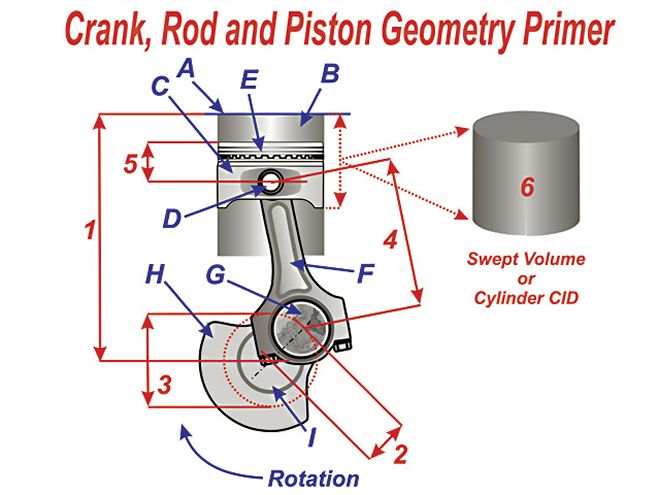
Components To Know:
A. Block deck
B. Cylinder bore
C. Piston
D. Wrist pin
E. Ring belt
F. Connecting rod
G. Rod journal
H. Crank counter weights
I. Main journal
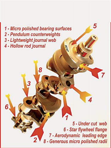
The SCAT Q-Light super crank shown here is the kind used in a maximum-effort engine such as an 840hp Nextel Cup unit. Such a crank seeks to satisfy three distinct criteria. Firstly, it must be strong and highly fatigue-resistant to endure the ultra high loads over extended periods. Secondly, it must have the minimum overall mass and the lowest moment of inertia possible to enhance vehicle acceleration. Thirdly, its windage should be as low as possible to cut internal aero drag and viscous losses. We will take a tour of this crank and detail its design philosophy.
1. The heat treat on the 4340 alloy gives it a very hard surface with a tough core. The super-hard surface, in conjunction with a micro-polish finish, ensures very low wear rates on all bearing surfaces.
2. Mass in and around the center of the crank is of no aid toward balancing the reciprocating components. To keep the crank light, the counterbalance mass needs to be concentrated as far from the crank centerline as possible, hence the undercut crank webs to form a pendulum counterweight.
3. The form of the web connecting the rod journal to the main journal is critical for a maximum performance crank. Too thin and the crank breaks, too thick and the counterweight necessary to balance it goes up. Everything in and around the rod journal needs to be light.
4. This is an extension of the last point, as a hollow journal means less mass is necessary on the counterweight to balance it out. Also, contrary to what you may expect, a hollow journal, if correctly done, is actually stronger than a solid one. A key ingredient here is the radius between the hole and the web of the crank.
5. From the front end of this crank it can be seen just how much the counter weights are cut away to reduce overall mass.
6. The star-form flywheel flange is mostly to reduce the crank's overall weight, although it does contribute a small degree toward moment of inertia reduction.
7. The aero leading edges of this crank cut aero drag and viscous losses. This is a big deal for crankcases that run at near atmospheric pressures. For a highly scavenged, low-pressure crankcase, such as in an all-out engine, the gains from aero mods are significantly less because the density of the air within the crankcase is less than half of normal.
8. The fillet radius on a crank has far more to do with its fatigue life than does the journal diameter. This being the case, attention to the fillet radius is important. Not only should it be as large as possible but also very finely polished to avoid stress risers.
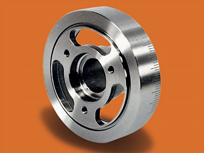
WHY YOUR ENGINE NEEDS A GOOD CRANK DAMPER
Forget what you have heard or read about lightweight crank hubs. They may have a lower moment of inertia, but do not deliver more power than a heavier crank damper. In the real world, it's not as simple as the dynamics of a crankshaft. At some point in the mid- to upper-rpm range, the damper will go into a bending and torsional vibrational resonance. In so doing, it will behave something like this.
10 Rules For Successful Stroker Builds
1. Select as long a rod as possible to minimize frictional losses from side loading and cut the engine's mechanical noise.
2. Select the lightest reciprocating components for the bottom end.
3. Use an effective crank damper.
4. Use an oil pan that keeps the oil away from the bottom end rotating assembly as entrainment will cost big power and may lead to failure.
5. Go for as high a compression ratio as possible as it will offset the engine's reduced mechanical efficiency due to its greater piston friction.
6. Use cylinder heads with valves as large as possible as there are a lot more cubes to feed.
7. Be sure to tighten up the cam's Lobe Centerline Angle (LCA) from whatever was optimum before by about 1 degree for every 16 cubic inches of capacity increase.
8. Increase valve lift by at least the same proportion as the increase in displacement.
9. Make sure the induction system has enough flow capability to handle the extra inches.
10. Try to keep the induction system cool as this makes more difference with a stretched engine.