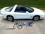
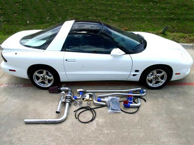
 The STS Turbo system for the '98-'02 LS1-powered Firebirds retails for $3,995 and comes complete with everything needed to bolt on well over 100 rear-wheel horsepower. Included in the kit are a Garret turbocharger, a patented STS oiling system, a TiAL wastegate, HPC-coated piping, a K&N air filter, and all the wiring, tubing, stainless hardware, and clamps to allow an enthusiast to add some serious power to his Bird in about a day's time. A bound instruction manual is included with detailed instructions and quality color photographs.
Our apologies, as the initials STS don't mean Subterranean Turbo System, but instead stand for Squires Turbo Systems, founded by Rick Squires in 2003. The fledgling Orem, Utah-based company's turbocharger systems are classified as rear and/or remote turbo systems, dwelling in the spot normally occupied by the muffler and/or after-cat exhaust.
Traditional turbo systems, be they from the OEM manufacturers or the aftermarket, have been placed under the hood, as close to an exhaust source (as it exits the engine) as packaging allows. Given these obvious differences in application, let's first examine the basics of a traditional turbo system, and then Rick Squires will explain how his goes against the perceived location requirements of turbo placement yet works well and even offers advantages over underhood turbos.
A turbocharger has one moving part, the turbine shaft, which is powered by exhaust gases. Since exhaust gases have a higher velocity close to the exhaust valves, conventional wisdom places it under the hood. After spooling up the turbine shaft, air is pulled into the compressor housing and sent out the side of the turbo to be fed into the intake tract. The shaft that spins the turbine and the shaft's bearings are cooled by engine oil, fed from the block. Exhaust gases never breach the intake tract, as the exhaust is simply the force function to turn the wheel. Heat generated at the turbo comes primarily from the exhaust charge that it sees, followed by the thermal energy imparted to the compressor housing by the spinning of the turbine shaft and the heat generated by the compressor side as the air is spun up (compressed and boosted).
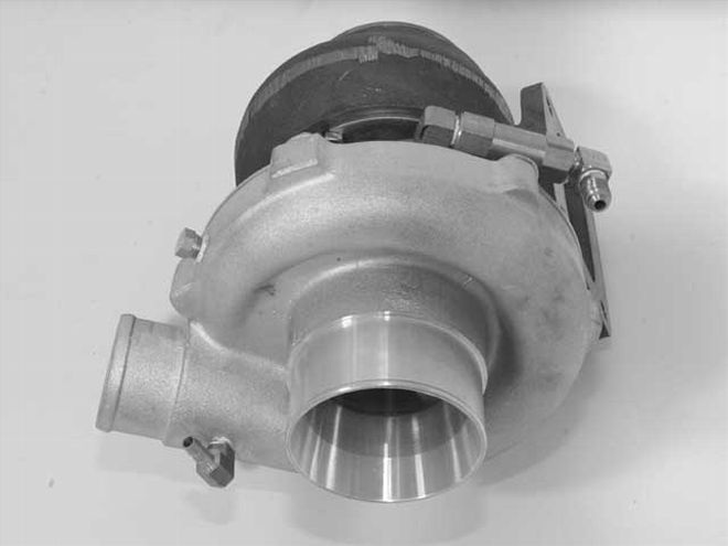 The Garret T04E turbocharger comes assembled from STS. Teflon tape is utilized to seal the supplied brass fittings. After ensuring the tape doesn't protrude past the threads, a 90-degree elbow is installed on the compressor side (bottom left) for wastegate boost control, and another 90-degree elbow, oil check valve (pressure switch), and 90-degree elbow install in the center for the turbine shaft.
This compressed air enters the engine at a factor above atmospheric conditions, thus forcing more air into the cylinders. The amount of air over and above the standard barometric pressure is what is defined as boost pressure, which is controlled by regulating the exhaust flow across the turbine via the wastegate (dump the exhaust and slow down the turbine speed). Left unregulated, boost will compound and destroy an engine in short order. Turbochargers are engineered based on the size of the engine that they will be on as well as the volume of compressed air needed. A properly sized and engineered turbocharger system will see little "turbo lag" and will address heat management of the compressed air via an aftercooler or other measure such as alcohol or methanol injection. Sounds great, right? But what if space is tight under the hood?
In today's cars, including the LT1- and LS1-powered F-bodies, underhood space is extremely limited. Sure, turbocharger systems exist for these vehicles, but the innovative approach that STS took in designing a system for your late-model F-body garnered the company the coveted GM Design Award for Best Performance Product at the '04 SEMA show. That's a high accolade, which makes this system worthy of a closer look at its origins, engineering, and development.
And who better to fill us in than Rick Squires, owner of STS? "I didn't start the business to go after the performance F-body market--it just sort of happened," Squires says. "Originally, I took my mechanical background and wondered why nobody ever designed a turbocharger system for late-model trucks that eliminated the two large problems with factory systems--underhood room and heat.
"A salesman for a large Toyota dealership in Salt Lake City purchased an '01 Toyota quad-cab 4x4 with a 3.4L engine. He wasn't impressed with the performance of the TRD superchargers that a few of the sales guys had, but was going to get one anyway. Then a friend suggested he contact me about a turbocharger system. I looked at the truck and there was enough room to do one under the hood, except that it wouldn't be able to pass emissions.
"Once I got the truck on a lift, it dawned on me that the area where the muffler sat would be a great place to mount a turbo. Eliminate the muffler, have the exhaust pipe that fed the muffler now feed exhaust gases to the turbo--a prototype later and the business began.
"After successfully launching a line of turbo systems for Toyota and GM trucks, a friend convinced me to design one for his LT1 Camaro. Finding success with that system, the LS1 crowd started beating a path to our door, demanding one of their own. We prototyped the LS1 system by using a locally owned '99 Camaro. The base LS1 package uses a Garrett T04E turbocharger with a 60-1 compressor and an 0.81 A/R turbine housing.
"A/R refers to the area of the scroll divided by the radius of the centroid of that area from the center of the shaft. Basically, the scroll starts far away from the center of the shaft and has a large diameter hole. As the exhaust passage scrolls around toward the turbine wheel, it gets closer to the center and the passage (area) gets smaller. In a nutshell, it is shaped like a curved funnel. The smaller the A/R number, the higher the velocity of the gasses will be when they hit the turbine wheel.
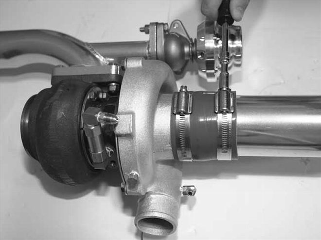 The air inlet pipe is installed onto the compressor housing with a 3-inch silicone hose and two 3-inch clamps. Each clamp is tightened using a 5/16-inch socket or a flat-bladed screwdriver.
"Smaller A/R housings spool up quicker than larger A/Rs but are more restrictive on top-end flow and horsepower. Too large a housing A/R will give you turbo lag, too small an A/R will suffer top-end power. Sizing the A/R correctly is based upon engine displacement, rpm range, and--what most of the world forgets about because in the traditional turbo location, it isn't really a variable--exhaust gas temperature.
"A front-mounted system for the LS1 would typically be designed utilizing a 0.96 A/R housing. In order to compensate for the minimal loss in thermal energy conversion as the exhaust travels to a remote location, an 0.81 A/R housing works great for a rear-mounted turbo system. The factory exhaust manifolds and Y-pipe do an excellent job of retaining the heat and allow a high exhaust gas velocity. By running the intake tubing underneath the car and using HPC coating on the charge pipes, we see a 52 percent reduction in temperatures between the compressor housing outlet and the temperature of the air as it enters the intake with far less pressure drop than a typical intercooler.
"The cooling properties of pulling in cool air from underneath the car and then using it to cool the charge pipes, effectively provide a natural intercooler effect (Passive Charge Cooling), eliminating the need for an expensive air-to-water or air-to-air intercooler core and plumbing. Turbo lag isn't an issue as once the exhaust is up to temperature, the specially matched turbo spools quickly. On a typical LS1 F-body, boost is all in by 3,000 rpm and, depending on load, comes in as soon as 2,000 rpm.
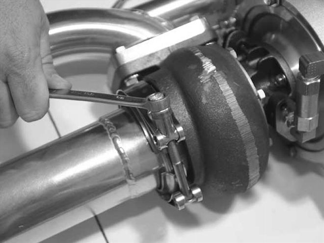 The exhaust pipe is mounted to the inlet of the turbine housing and secured with a 3-inch V-band clamp using a 1/2-inch box-end wrench. We didn't completely tighten the clamp, as we'll want to adjust the orientation of the pipe where the exhaust pipe exits.
"By relocating the turbo to the rear of the vehicle, the turbocharger itself doesn't contribute to heat-related problems seen in conventional placement systems. Air is constantly flowing over the turbo when the vehicle is moving, so the housing stays cooler, eliminating additional expense for items such as turbo timers. Many F-body customers have reported gains of 2-4 mpg, at least those who can resist the urge to keep their right foot from constantly being planted on the floor."
Now that you know the premise of this product, follow along as an STS rear turbo system is installed on an LS1-equipped '00 Formula WS6. STS' sequential methanol injection kit will be added to allow the base turbo boost pressure of 5 psi to be raised to 71/2 psi. Installation was done at Real Performance Motorsports and DuSold Designs, both located in Lewisville, Texas, by technicians from Texas Rear Turbos, an Arlington, Texas-based factory trained distributor and full-service installer of STS turbo systems. In Part I, we will introduce the components of the bolt-on kit and dive into the installation.
The spray nozzle is installed by drilling a 21/64-inch hole in the air intake tube that connects from the MAF to the throttle body. A 1/8-inch NPT tap makes threads, and Teflon tape is put on the nozzle's threads before it's carefully tightened. The methanol injection is introduced into the system after the MAF, but before both the IAT sensor and throttle body. The 50/50 mix of methanol and water that is run will significantly reduce the intake temperatures, and we need the computer to recognize that, thus the placement before the IAT sensor. Needless to say, spraying any liquid into the MAF will quickly stop the engine from running and may damage the delicate electronics.
Recommended Tools
Recommended Parts and Supplies