
In the mid '70s, GM began offering its SI-series (Systems Integrated) alternators, which not only delivered more amperage but did away with the externally mounted voltage regulator and its messy wiring. Installation is simple and the appearance has a factory look. Check out how we installed a Delco-Remy 12SI alternator on our '70 Chevelle (which formerly had an externally regulated alternator) using a wiring kit from MAD Enterprises. If your application varies, don't fret; MAD offers a variety of wiring diagrams and kits to ease installation on most any musclecar--including Ford, Mopar, and AMC muscle machines!
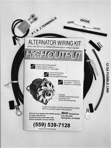
For about $25 you can score MAD Enterprises' alternator wiring kit (PN ALT-1) and ease the installation of a more modern factory-type Delco-Remy 10SI or 12SI alternator. The kit includes items such as a special connector and terminals for the alternator, heavy-duty 8-gauge TUFF-WIRE, wire terminals, shrink tubing, a fusible link, an inline diode (not required for all applications), and an easy-to-follow instruction booklet complete with wiring and troubleshooting tips.
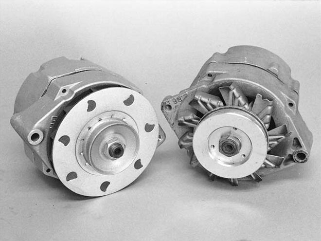
The appearances of an SI-series alternator (left) and a vintage '60s DN-series alternator are similar--yet their rated output is much different. While a DN-series alternator struggles to produce 40 amps, most 10SI alternators deliver a steady 63-amp power supply, and some 12SI units churn out a whopping 94 amps. Although pulleys are similar, a 10SI comes with a metal cooling fan, whereas the 12SI has a larger plastic fan. Our stock alternator (right) has an aftermarket underdrive pulley, and, if desired, pulleys interchange between DN- and SI-series alternators.
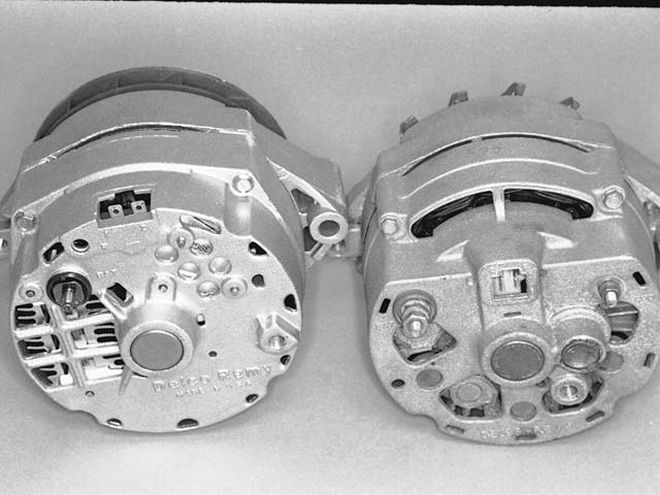
The SI- (left) and DN-series alternators have different style plug-in connectors (arrows). On 10SI/12SI units, the rectangular plug locations are labled 1 and 2, whereas the DN-series uses a more square connector port labeled R and F. Out back, a 12SI has much larger cooling vents than a 10SI, and a 10SI has more cooling vents than an older DN-series alternator. Besides having a higher amp output, SI-series alternators also begin charging at much lower engine rpm (which is beneficial when cruising, for example) than older-style alternators.
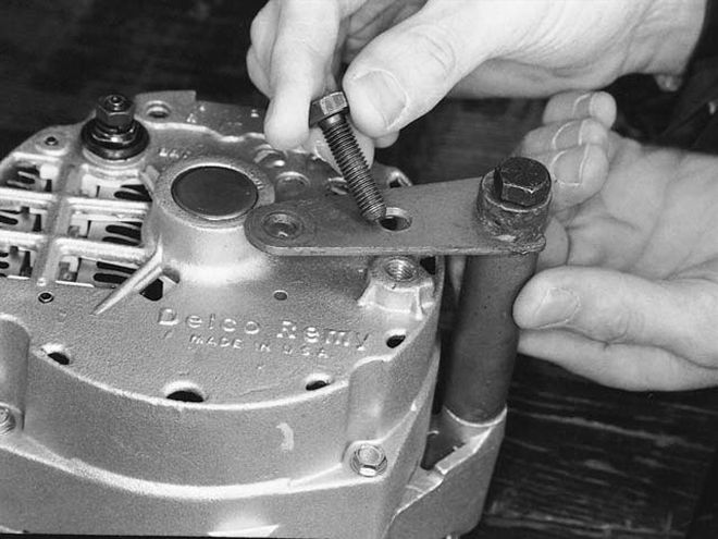
The stock DN-series alternator uses a bracket that serves as both a mount and a ground. A similar mount/ground is needed for the new 10SI/12SI alternator. Our stock mount was close to correct for a 10SI/12SI, but had the ground bolt in the wrong location. We drilled a new 11⁄32-inch hole, used a few washers for spacers, and threaded-in a new M8x1.25x30 retaining bolt. If you want the correct bracket for the conversion, order GM PN 14079285.
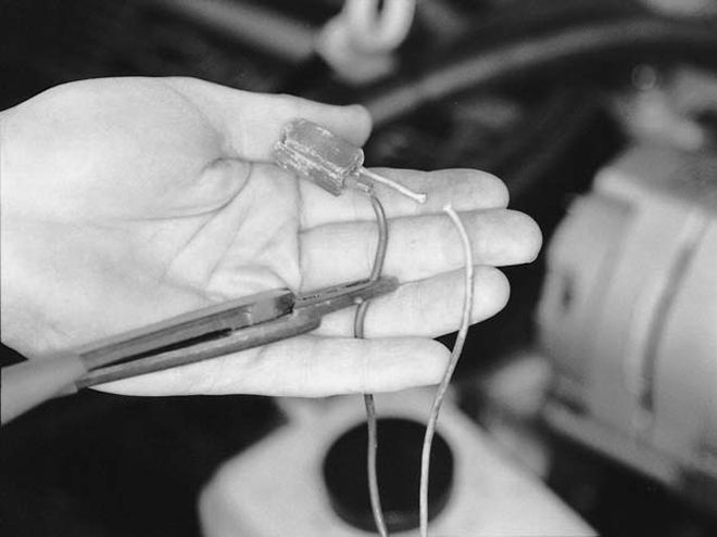
Convert the DN alternator's two-wire connector to the new SI-type connector (supplied). If they're in good shape, you can reuse the old terminals. However, our stock wire-ends were tattered near the connector, so we cut the wires about an inch away from the terminal.
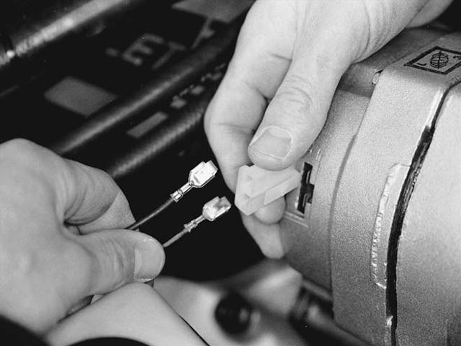
We installed the kit-supplied wire terminals (crimping works but soldering is better) and then inserted the terminals into the new kit-supplied 10SI/12SI-type rectangle connector. Be sure to orientate the wires correctly when installing them in the clip--the stock blue wire goes to the alternator's 1 terminal while the white wire should go to the 2 terminal. Note: If you've upgraded to an aftermarket capacitive-discharge ignition system (such as an MSD or Crane unit), you'll need to wire a special diode (included with the MAD kit) somewhere along the blue wire that leads to the alternator's 1 terminal to prevent run-on problems.
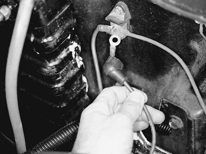
If you're installing a 63-amp 10SI alternator, simply reconnect the alternator's factory charge wire. If you're installing a big 94-amp 12SI unit, use new 8-gauge wire (supplied) to replace the stock 10-gauge power wires that run from the alternator to the horn relay and from the relay to the junction block, often located near the battery on pre-'71s. We ran MAD's supplied 8-gauge wire from the alternator's charging terminal to the horn relay, retained the old 10-gauge relay-to-junction block wire, and then connected the alternator's old 10-gauge charge wire to the terminal block. "Doubling up" the two stock 10-gauge wires creates two paths of energy travel that roughly equate to using one new 8-gauge wire--all without disturbing any of the factory in-harness splices.
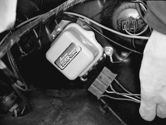
Disconnect the factory four-wire connector that attaches to the stock (externally located) voltage regulator mounted on the driver-side area of the radiator core support. Use wire cutters to cut the four wires exiting the connector, then...
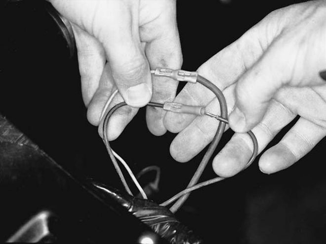
...connect the blue wire to the brown wire. Next, connect the white wire to the red wire. Afterward, the stock external voltage regulator can be discarded.
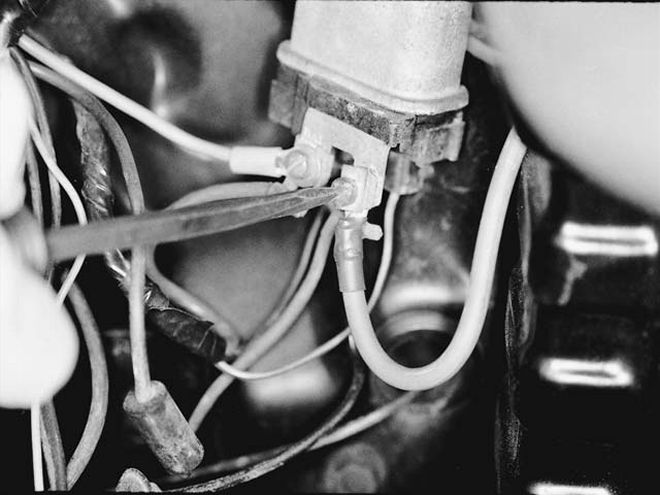
Here we installed the new 8-gauge wire (supplied) from the horn relay to the charging wire stud on the back of the new 10SI/12SI alternator. The MAD kit comes with the proper terminals and heat-shrink terminal insulators for both ends of the wire, but you'll have to get an M6x1.0 nut to attach the wire to the 12SI alternator stud. The charging system should then be ready for use. CC