In the last installment, we looked at various modifications on the intake side of the production 440 heads, and modified them to inhale mass quantities of air. All that added charge coming in will require a proportional increase in flow on the exhaust side, to keep things in balance. After increasing our peak intake port flow by more than 30 percent, we set a similar target increase on the exhaust side. Using Dave Vizard's Quadrant Scientific FlowLab, the stock exhaust flow peaked in the low- to mid-150cfm range. Taking that number as our base, we were looking to pick up the exhaust flow to the neighborhood of 200 cfm. A glance at the charts in the January and February segments of this series, and you'll realize we're looking for nearly the flow of the stock intake port from our modified exhaust ports!
The Exhaust Ports: Sizing 'Em Up
Some may argue subtle differences--real or imagined, planned or coincidental--exist between the exhaust ports of the various 1967-and-later castings. For all practical purposes, the exhaust ports are shaped about the same, flow about the same stock, and respond to modifications in about the same way. Working with a wide range of 1967-and-later big-block heads--the 915, 906, 346, and 452s--we found no consistent differences in flow between the various castings in modified form. In surveying the intake side last issue, there were two distinct styles of intake ports to consider. In discussing exhaust modifications, we will consider all the 1967-and-later exhaust ports as equivalent.
In our first installment of this series, we tabulated the stock flow of the various castings, then looked at the flow improvement when the various ports were ported with the Mopar Performance templates and the stock valve given a 30 degree back-cut. To recap briefly, variation in peak flow on the exhaust side, between the various castings modified to that point remained within 2 percent. You'll find that much variation from port-to-port on the same head.
Exhaust Modifications: The Stock Valve
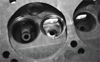
We begin our third segment in this evaluation by reworking the exhaust port while still utilizing the stock-sized 1.74-inch valve. The flow of the exhaust port is strongly biased to the roof, so this is where we begin our modifications. Our first move was to mildly blend the ridge at the guide-boss web. This was blended into the long side pocket, and down the steep step to meet the roof (Photo 1). This minor modification netted us the flow figures shown in Table 1, Column 3. With the stock-sized valve, there was nothing to be had--we actually lost a few cfm on our template-ported base. Next, we went back into the roof and blended out the roof hump, narrowed the guide, blended the roof to the walls and guide, plus further smoothened the transition on the pocket-to-roof step and into both walls (Photo 2). Our reward for all this effort can be found in Table 1, Column 4. We were a few measly cfm from where we started. It looked nice, but where was the flow?
At this point, it was time to review our progress from square one. While the template-porting modifications completed in Part 1 of this series improved exhaust port flow at very high lifts by a sizable margin, below .450-inch lift, there was little gain. At the other end, we saw a large jump in low-lift flow (less than .200 inch). In the all-important street lift range, from .250-.400 inch, our template-ported exhaust was improved just a little over the stock port. Even with the mods displayed in Columns 3 and 4 of Chart 1, the flow in this range still showed little change. Our large jump in low-lift flow over a stock head was a direct result of the back-cut on the production valve. More port work was not going to be much of a player in improving the low-lift flow beyond our initial valve mod. At the top end of the lift range, the big jump in flow resulted from the template-porting opening up the bowl area, thus letting the valve work efficiently at higher lifts. Yeah, it flowed a lot better, and it will make more horsepower, but we are cheating the port with the better valve down low, and only high-lift race cams will ever touch the improved flow on top.
The Lesson
All kinds of port modification work with the stock size valve yields little improvement in the typical street lift ranges. The problem with the stock production exhaust port is a nasty form in the shortside. Just behind the valve seat--where the shortside turn is supposed to be--we find a large, hollow area which represents dead air space. At best, it's an impediment to flow, and at worst, it can help contribute to horsepower-robbing flow reversion. The good news is, as the valve diameter is increased, this hollow area is largely reduced, allowing for a much better--if less than ideal--form. Although the intake port, as we learned, can be made to flow quite well with the production valve, on the exhaust side, working with the stock valve is like swimming upstream.
Bigger Valves
Our next move was to install the commonly available 1.81-inch exhaust valve, with a 45-degree seat. The 30-degree seat has not proven successful on exhaust valves, and we have never tried it on our heads. Once again, we used the Serdi seat cutter, cutting the 45-degree seat angle, with a 30-degree top cut and a steep 75-degree bottom cut. To prevent shrouding, the Serdi also was used to plunge-cut the chamber wall to the gasket line, concentric with the seat. The shortside turn now will gain material, so its form is critical. The turn should be profiled to as large of a radius as the precious little material will allow, dropping straight down into the turn just off the exhaust valve seat. The 1.81-inch valve paid off handsomely, with about a 20cfm improvement from the top all the way down to .300 inch, with significant gains down to .150-inch lift (Table 1, Column 5). With the bigger valve, we were finally able to achieve sizable gains in the previously dead lift ranges. How-ever, low-lift flow below .100 inch was actually down fairly substantially, despite the bigger valve. That proves that our modified factory valve was actually doing well at low lifts.
The back profile of an aftermarket valve doesn't have the factory valve's "ski-jump" ridge on the backside, so obviously, we couldn't remove it. In fact, back-cutting on the exhaust valve helps improve flow in both directions. So, as much as it helps low-lift flow out of the cylinder, it will promote undesirable reversion when used with high-overlap performance cams. Since exhaust flow from the cylinder is what we are after, looking for improvements to the exhaust valve's profile is not quite the same as with the intake. To help exhaust gas flow around the face of the valve, and outward back across the seat, putting a radius on the valve margin is successful. We added a radiused margin to our new valves, and with no other changes, the results in Table 1, Column 6 were obtained. The radius margin brought low-lift flow back into line, to the tune of a 14-percent improvement at .100 inch over the out-of-the-box big valve. At this stage, we were well within reach of our initial goals, with a peak flow improvement of 25 percent over the stock port.
Adding Polish
Usually, surface effects on flow are minimal, and in the intake port, a rougher surface may even be desirable to help keep fuel in suspension, but it is a common modification to polish the exhaust port. Polishing the Chrysler big-block's exhaust port is a relatively quick process, thanks to the port's easy access and short length. Polishing helps to prevent future carbon buildup, and while working with the sanding roll, subtle additional areas to blend will show up, which also promote flow. We polished the exhaust port, blending the roof and port walls for a smooth transition from the port pocket to the port exit. The floor of the port is already too low, so it was only carefully polished to remove the rough as-cast surface, and a gentle radius was given to the transition midway down the floor where the angle changes toward the exit. Once polished, the port picked up flow through most of the curve (Table 1, Column 7).
Finally, we went to the chamber. Here, the mods begin with cutting the chamber wall up to the head gasket line, in the vicinity of the exhaust valve. The gasket edge is marked, and the circular sweeping cut made by the Serdi is blended into the adjacent chamber wall. Cut past the gasket line and the head gasket will never hold, so grind cautiously. Next, the machining ridge circling the seat is blended flat with the chamber roof, and the chamber is polished. The effect of the chamber mods was a healthy increase in flow above .350-inch lift. (Table 1, Column 8). We had now reached our goal of a 30-percent improvement in peak exhaust flow, with the entire curve fattened up nicely, to the tune of nearly a 25-percent improvement in total area under the curve.
Flow the Easy Way
In the previous example, our first two levels of port mods (Columns 3 and 4) were done before installing the larger valve, to little or negative effect. The question remains on how those bigger valves would have worked if they had been installed in a template-ported head with no additional port modifications. We dusted off another casting which had been ported to the templates, and installed the 1.81-inch valve, using the Serdi to cut the aforementioned seat. The chamber was plunge-cut to help deshroud the valve. The bottom cut was lightly blended into the bowls and around the shortside. We found that the 1.81-inch valve worked quite well in this mildly modified form, giving us the flow numbers shown in Table 1, Column 9. In terms of total area under the curve, this configuration was within 2.6 percent of our previous port in Column 6, and within 6.8 percent of our fully modified port in Column 8. In other words, strong gains can be achieved with a template-ported bowl, the correct shortside form, and a good seat working with a radius-margin 1.81-inch valve. The big-block Mopar exhaust port really responds to the 1.81-inch valve. This type of a port would work great in a street/strip application, with minimal effort. The bottom end of the curve would be nearly identical since this is primarily a function of the seat and valve forms. The guide, roof, and port work adds incrementally to our fully ported exhaust flow on an already good package.
Don't Blow the Flow
On the other hand, don't be fooled into thinking that you can't go wrong by installing only the bigger valve. We had on hand another head, with the 1.81-inch valve installed by a local machine shop. Mistake number one was that the bowls weren't opened up to even the template size, and a shallow 60-degree bottom cut was used (a 75-degree bottom cut would have helped by removing much of the material that the templates would require you to remove). The shallow bottom cut on these heads was only mildly blended, and the valves were out of the box, without the radius-margin modification. Testing (Table 1, Column 10) revealed that they didn't even match the flow of a stock 1.74-inch back-cut valve in a template-ported head.
Taking the lessons learned here, the production exhaust port can be brought up to flow by about as much as the intake did originally. Overall, the port in Column 8 brought the total area under the flow curve up by 25 percent, compared to the stock port. That's more than three times the improvement of the template-port job alone. As in our intake port modifications from Part 2, the modified exhaust flow was significantly fatter from way down low, all the way up to maximum lift. How much is all this worth in the real world? We plan on putting the heads on the 440 race engine. Once that engine is built, and a dyno facility has been located, we'll share the real power numbers.