Being the hopeless hot rodders we are it's only natural that we all like going fast. But, as much fun as we may have doing so, at one point or another we're gonna have to slow down or even stop. So, it's with this in mind that we thought we'd take a look at a street rod brake system going together while sharing some highlights regarding components, forming and flaring hard line, and even a bit about the installation and routing of brake lines.
When it comes to planning a hot rod brake system there are a few considerations to keep in mind. Most important would be a system's performance, unfortunately sometimes overlooked for the sake of traditionalism. Sure, a drum/drum system does look old school and harken back to the early days of rodding, and in a lightweight vehicle four-wheel drums may be adequate. But, for those that couple either high-performance engines in lightweight hot rods or even in larger, heavier, fat-fendered classics, a disc/drum combo may be a better choice. Along these same lines would be the choice between manual and power-assisted systems.
System components are an important choice too and a dual reservoir master cylinder is at the top of my list for sure. Lose a line or a wheel cylinder in a single reservoir system and you've lost all your brakes; lose a line or wheel cylinder in a dual reservoir system and at least you lose only one circuit, leaving you with half a braking system. The balance of brake system components consists of metering valves, proportioning valves or adjustable proportioning valves, and in some cases residual pressure valves. The following explanations come care of my friend Ralph, the head cheese and driving force behind Engineered Components Incorporated (ECI) back in my home state of Connecticut and one of the smartest street rod brake system engineers in the field.
Hold-Off/Metering Valves are used in the front (disc) system of a disc/drum brake system. They provide a "hold off" function to allow the rear (drum) brakes to actuate first. This function is very important in making the system function in the correct sequence in a rear-wheel-drive car. The rear brakes are always actuated first. This function is built into most factory-type disc/drum combination valves. Make sure you have a metering/hold-off valve in the system either as a stand-alone valve or as part of a factory valve.
 For many the chore of plumbing a street rod braking system seems like a daunting task but with a bit of research, planning, and patience one can complete the job with confidence and pride.
Proportioning valves go in the rear brake system (disc or drum) and provide for control of the rate of pressure rise to the rear brakes—just the rate at which it builds up. Sooner or later the rear brakes see full master cylinder discharge pressure. The purpose of this rate of pressure rise control is to compensate for the reduction of weight on the rear wheels due to forward weight transfer during braking. In short, it eases the application of the rear brakes to help prevent rear wheel lockup. Factory combination valves have these built in—make sure you know what you're getting; too little rate of rise is as bad as too much. You may not need one of these valves, depending on the compatibility of your vehicle's brake system components.
Adjustable Proportioning Valves allow for fine-tuning of the rate of pressure rise to the rear brakes if you have a lockup problem. If you do have a lockup problem, experiment with the setting of the valve to eliminate lockup for all but all-out panic stops.
Residual Pressure Valves are used in both front and rear brake systems as follows: 2-psi valves—these valves are used in a disc brake system only and are required when the master cylinder is at, or below, the height of the calipers. Its purpose is to act as an anti-siphon valve preventing the brake fluid from siphoning back into the master cylinder when the brake pedal is released. Even if the master cylinder is even or slightly above the calipers, put one in anyway. If you don't and you park on a hill, fluid will siphon! These valves are cheap insurance—put them in! Note: You will know if you need one of these valves if you have to pump the pedal twice to get a good pedal. Next, 10-psi valves—these valves are used in a drum brake system to prevent air from being ingested into the hydraulic system when you release the brake pedal. Typical wheel cylinder seals only seal when there is pressure behind them. Rapid release of the brake pedal creates a vacuum in the system, which causes the seals to relax and air is ingested into the wheel cylinders. Maintaining 10 psi in the system at all times prevents this. Some disc/drum master cylinders have 10-psi residual pressure valves installed internally, some don't. Also, some new-style wheel cylinders have cup expanders that negate the need for the residual pressure valve. Either way, if you are not sure whether you have one or not, put one in. They are not cumulative and it won't hurt anything if you have two. Don't worry about brake drag; it takes roughly 75 psi to overcome the return springs.
So with these few nuggets of wisdom let's take a look at a typical street rod brake system going together.
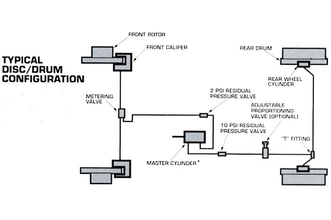
1. This diagram (thanks again to the folks at ECI) is a great reference for a novice brake system fabricator to have on hand as reference. I know it was a great help to me on my first few system fabrications. As you can see, with the inclusion of the two residual pressure valves in the diagram the example master cylinder is assumed to be on an equal plain with the front calipers or slightly below. On systems with high-mounted (firewall or under dash) master cylinders the residual valves are not absolute requirements.
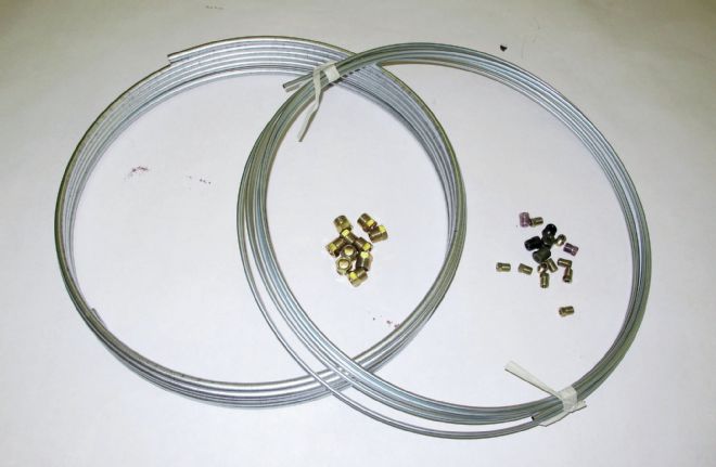
2. On this particular brake system fabrication a bulk stainless brake line and fitting kit sourced from Speedway Motors was chosen over the use of multiple lengths of auto parts store brake line. Using the bulk rolls allowed the installer to fabricate the system with the least amount of junctions as possible, cutting down the opportunities for leaking connections.
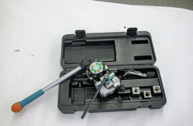
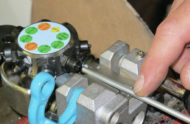
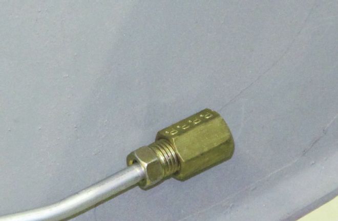
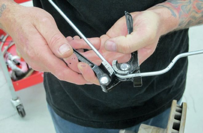
3. For the task of flaring the stainless brake line (which is much harder to work than conventional steel line), Jason Scudellari (our tech center manager) enlisted the aid of the Eastwood Professional Brake Tubing Flaring Tool (PN 25304). The tool mounts in a vise and easily forms 45-degree single, double, and bubble flares in steel, stainless steel, and soft metal tubing for 3/16-, 1/4-, 5/16-, 3/8-inch-diameter lines—which means it will handle brake lines, transmission cooler lines, and fuel lines as well. The tool's "turret-style" design makes precision flares quickly and all the brake-flaring forming dies needed are mounted right on the turret, so there's no fumbling for small parts, no worry about missing dies—its T-handle screw clamp securely holds line in place during forming too.
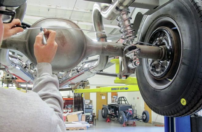
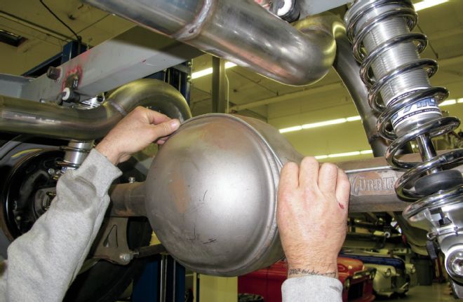
4. Scudellari began the plumbing job at the vehicle's rearend. After flaring the first section of line and making the slight bend as the right rear wheel brake cylinder he proceeded to mark the locations for the bends needed to follow the contour of the rearend centersection.
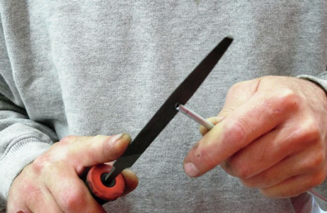
5-6. A quality tubing cutter is a must; clean cuts are important prior to flaring for leak-free connections, as is cleaning any burrs from the tubing's ID.
7-8. Without reciting the complete operating instructions of the Eastwood flaring tool take my word for it, it's quick, easy, and a heck of a lot more successful than using the old clamp and wing nut double flaring tools we're perhaps used to seeing and using. Suffice to say, if you even think there's more than a couple of brake plumbing chores in your future this Eastwood flaring tool is a must for your toolbox.
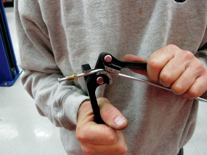
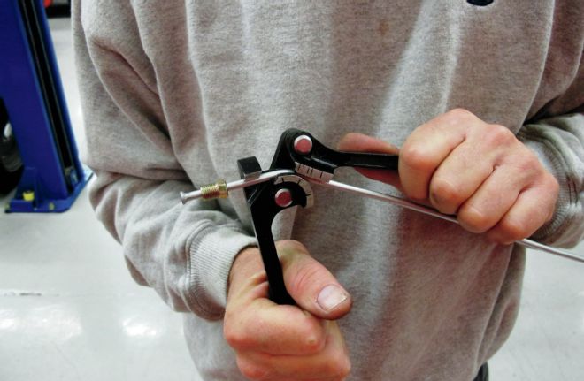
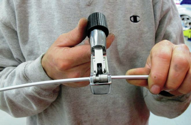
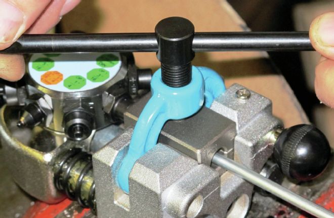
9. With the brake line cut, deburred, and lubed by a touch of antiseize compound, inserted in the clamping die, the turret aligned with the correct size operation-1 flaring die, the lever is pulled with sufficient force to create a bubble flare. To create a double flare the die head is spun to the appropriate size operation-2 die, lined up, and the handle pulled again with sufficient force to create the inverted portion of the double flare, and you're done. One perfect 45-degree double flare down quickly and cleanly.
10. With the first flare and bend complete the line is threaded into the wheel cylinder and attention is turned to forming the radius at the rearend centersection.
11-12. With the line marked at each bend point Scudellari makes the first of the bends needed to follow the upper radius of the rearend.
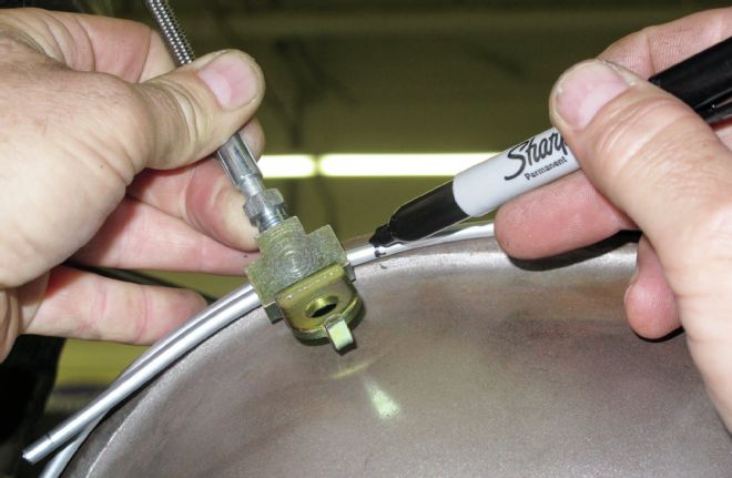
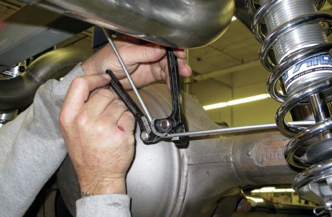
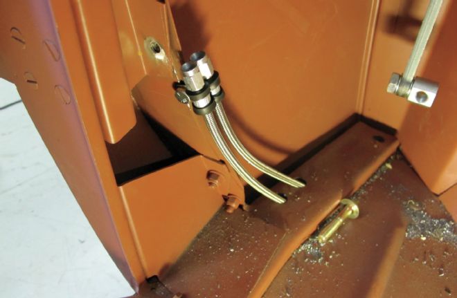
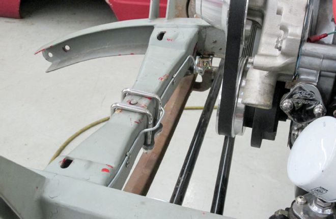
13. After forming a second line from the left side wheel cylinder toward the rearend center the lines are marked where they'll be trimmed, flared, and threaded into either side of a three-way union. A flex line is attached to the center of the union and will connect the rearend lines with the hard line that'll run down the left framerail forward to the underdash mounted master cylinder.
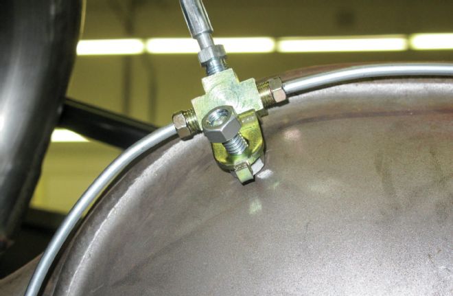
14. Scudellari then got ready and welded a 1/4x1-inch bolt to the rearend housing to use as an anchor for the three-way union.
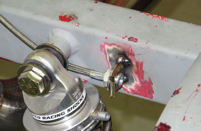
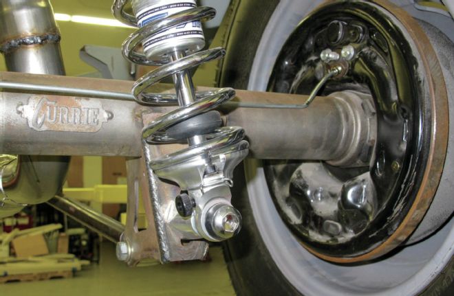
15. The flex line from the union is run from the rearend hard lines to a tab on the rear coilover crossmember toward the left framerail.
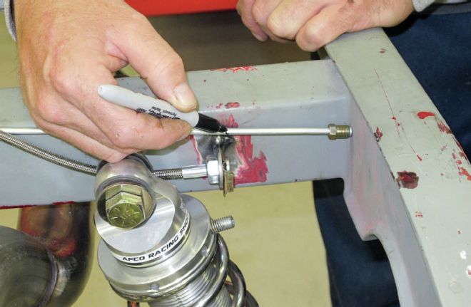
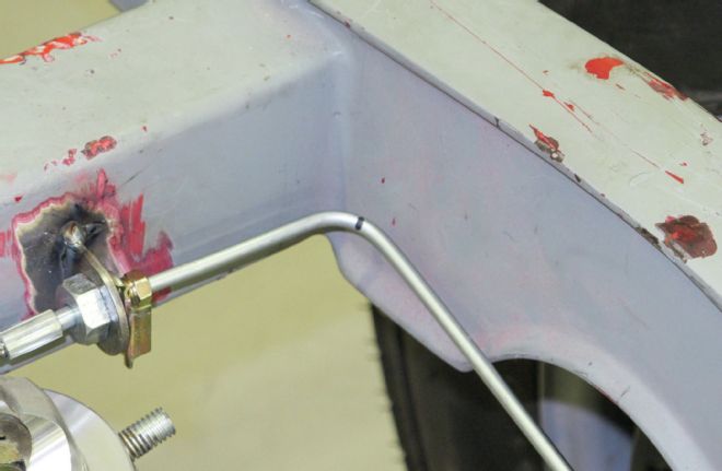
16-17. The next section of hard line is then measured, marked, and bent so it runs from its junction with the rear flex line to and then forward down the left framerail.
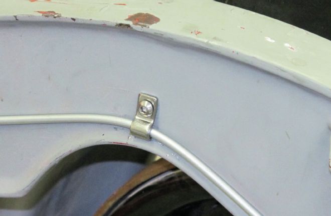
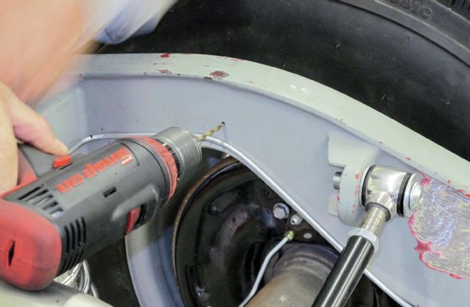
18-19. The hard line is bent to a bit of a radius following the contour of the framerail and a hole is drilled and tapped to accept the first of a few line retainers used to snug the line to the framerail.
20. In this particular case the vehicle is equipped with a Kugel Komponents underdash master cylinder and pedal assembly so the hard line run forward on the left framerail is terminated just under the body cowl side and fitted with one of a very few brass unions used in the complete system.
21. One of the two braided flex lines seen here is attached to the aforementioned brass union and will be run upward and under the dash and attached to the metering valve and master cylinder. The second braided line will do the same from the front brake plumbing.
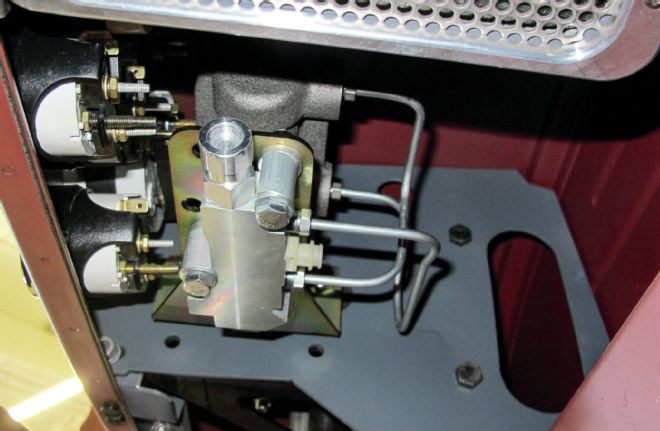
22. Here's an image looking up under the dash at the Kugel brake pedal/master cylinder/metering valve assembly. The setup is a great option for times when a firewall or under-floor master cylinder is unwanted or impossible.
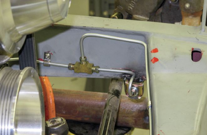
23. The forward brake hard line will run from the second braided flex line from the master cylinder again along the left framerail to just rearward of the front frame crossmember. A second three-way brass union will connect that line to a short section that connects to the front braided flex line to the left front caliper and a second hard line that'll run across toward the right front caliper.
24-25. A few more measurements, marks, and bends and the final piece of hard line is formed and run from the left front line junction to the right side connection with the braided flex line to the left front brake caliper. And there you have it—a typical street rod brake plumbing job. The final step would be to fill the master cylinder, begin to bleed the system, and check for any leaks.