I think it's pretty safe to assume that we all begin planning the assembly of our street rod projects with a mind's-eye view of the style we'd like to emulate (traditional, contemporary, show rod, driver), our choice of year, make, model, the composition of its driveline, its stance, wheel/tire choice, and so on. But we all know there are always specifics we can't truly address until we're at the point of actually turning wrenches.
A great example, as in this particular case, is the steering system. Sure, we can plan in advance whether we'll use a rack-and-pinion or a standard steering gear, manual or power assist, and our choice of column and steering wheel styles. But as I said, once we do we still won't know exactly how we'll tie the system together until we're ready for the mockup or assembly stage. Here we'll use the steering connection on our Model A pickup as one example of a common Vega-style, gear-operated cross-steer system in our Speedway Motors chassis.
It's always a good idea to begin setting up a steering system after the engine is in place and the exhaust manifolds or headers are installed. Completing the steering connection at this point ensures that no part of the steering system occupies the same space as other critical engine bay components—an unfortunate and totally preventable turn of events I've encountered myself in the past. When making the steering system connection the angle of the steering column, shaft(s), U-joints, and shaft supports with respect to the steering box/rack-and-pinion is important. You always want the setup to be as direct and simple as possible—so follow along as we put together our system.
 Proper planning and installation of your steering system is a no-brainer if a bit of time is spent eyeballing the most comfortable steering column angle and the most straightforward, simplest routing of shafts and joints in regard of the steering gear or rack-and-pinion.
1. The Model A pickup installation is a good example of a simple traditional-style street rod steering/suspension setup—a buggy-sprung solid axle using a cross-steer configuration and a Vega-style steering gear, hot rod column (Speedway Motors sourced), and stainless Borgeson Universal Company U-joints and Double-D steering shaft.
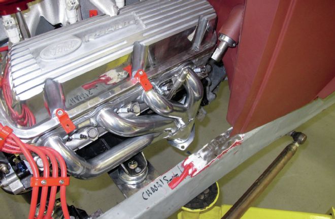
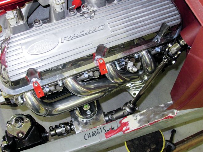
2. At first glance it looks as though this particular setup will be a pretty straight shot. With the steering gear installed, the column angle determined, and the appropriate column drop chosen and installed it's now time to determine the easiest way to route the system past the Ford Racing 302 V-8 and coated Patriot Exhaust Products flat-collector headers (part# H8482-1) ,under the motor mount and on to the steering gear.
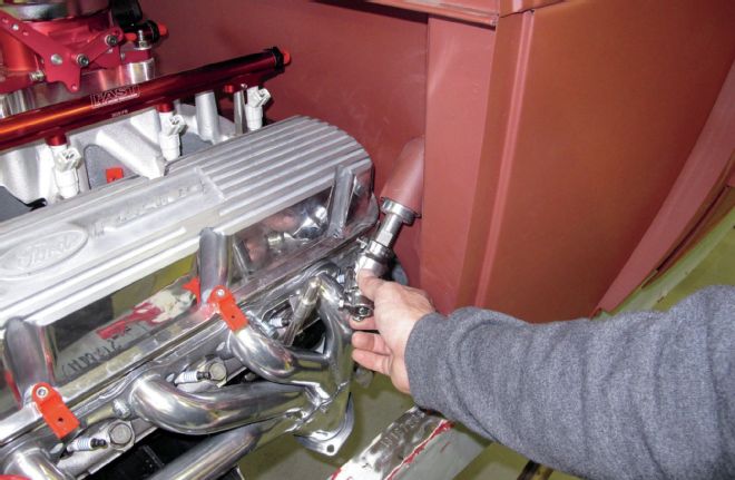
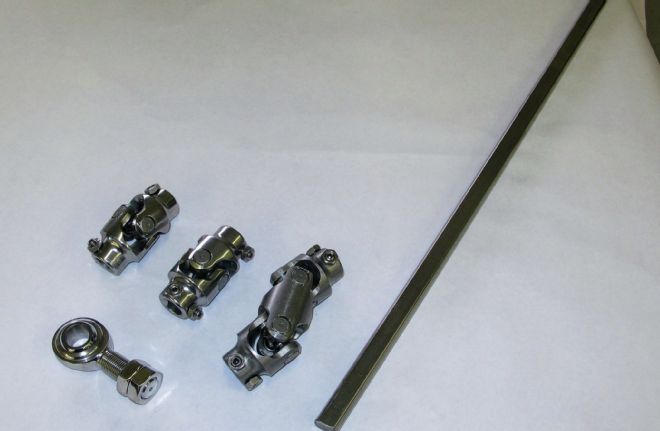
3. The setup can be started from either the box/rack-and-pinion end or from the column forward. The first component in the process was a standard stainless Borgeson U-joint machined for use with a double-D shaft at each end attached to the Speedway steering column. Borgeson needle bearing universal joints are CNC machined in steel, stainless steel, or aluminum. The company's ongoing engineering and testing ensures strong, safe, smooth operating steering universals with huge advantages over non-needle bearing joints.
4. A second U-joint is attached to the steering gear, thus providing both a starting and ending point. By the way, Borgeson U-joints are available machined out of different materials but they're available in an astounding 6,237 variations from the double-D used at the column end to combination splined and double-D configuration like the 3/4-inch/36-spline used at the steering gear end in this case. (By the way, single U-joints have a maximum usable angle of 35 degrees.)
5. The way this particular steering box is configured and mounted its input shaft protrudes at a slight upward angle from horizontal, necessitating a short section of steering shaft run nearly horizontally under the engine mount assembly. In order to make the transition angle from the short section of the shaft to the second longer section of shaft running toward the joint at the column end (and at a greater than the maximum single U-joint angle of 35 degrees) it was necessary to utilize a double U-joint, which are capable of angles up to a 70-degree maximum.
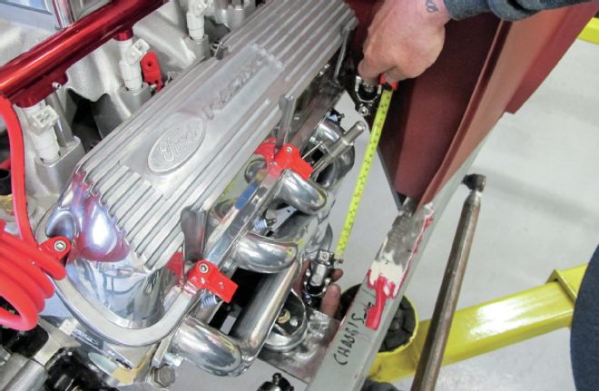
6. From the double U-joint a measurement is taken to determine the length of the second section of double-D shaft. Speaking of shafts, Borgeson manufactures stainless steel steering shafts in both splined and double-D. All of the splined shafting has a 3/4-inch/36-spline with 7/8 inch of spline on each end. Splined shafts are available in 1/4-inch increments from 3 to 24 inches and 1-inch increments from 24 to 36 inches—stainless shafts only have 7/8 inch of spline and cannot be trimmed. Stainless steel double-D steering shafts are available in 22- or 36-inch lengths and are "D" shaped the entire length. These can be easily trimmed to any length, as you'll see.
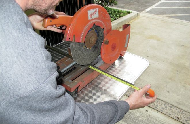
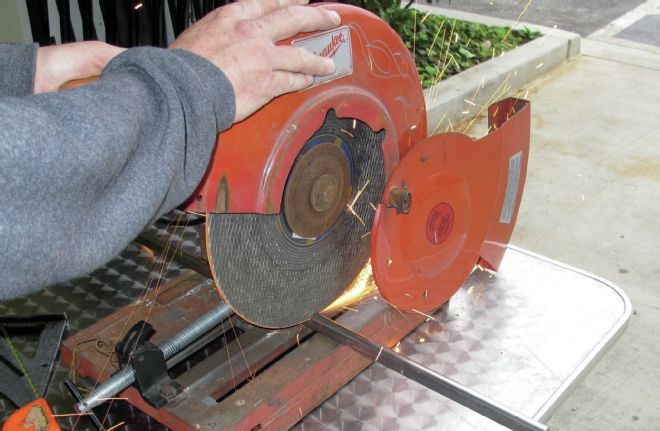
7-8. The measurement is then transferred to the length of shaft and an appropriate section cut to length.
9-10. I forgot to mention a couple of things earlier. One is that it's important to bevel the edges of the cut ends of double-D shaft(s) to aid in sliding them into the U-joints, and it's important that the shafts not be slid into the joints too deeply as it will bind the joints, freezing them up.
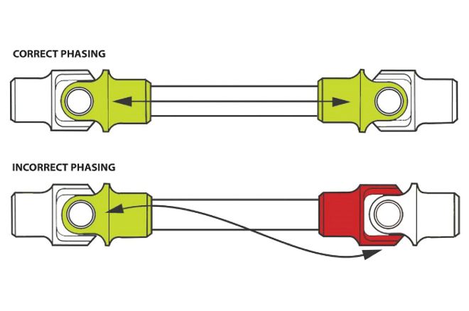
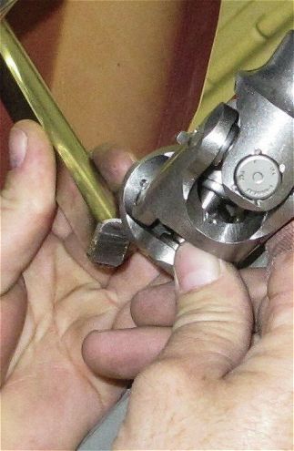
11. Note: Whenever two joints are used on a shaft the joints must be phased. In other words, the forks of the yokes closest to each other should be in line (in phase), if not binding or premature wear may result.
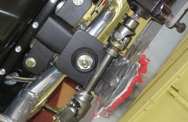
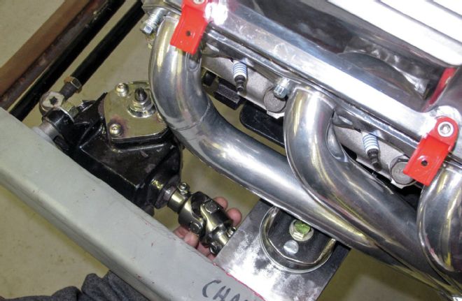
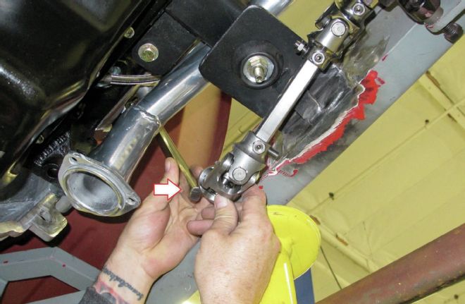
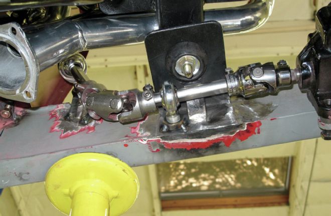
12. Here's a view of the setup from below. The uppermost joint in the image is the single U-joint at the steering gear and the lower double U-joint in the image is the one making the sharper angle connecting the short lower shaft angling up to the longer shaft to the column.
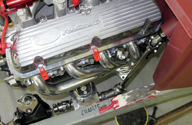
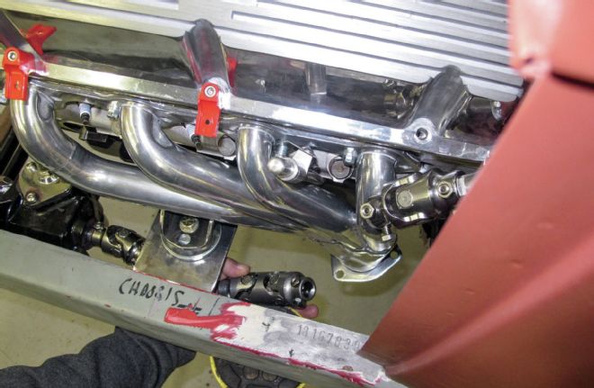
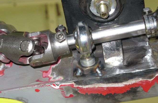
13. This view from the top looking down toward the framerail you can see the lower part of the system mocked up and in place. To the left a single U-joint (one end splined, one end double-D) connected to the steering gear and a double U-joint (double-D on both ends) on the right.
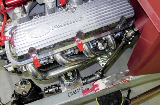
14. Zooming out a bit shows the complete connection between the steering gear and the column.
15. Because this setup required a three-joint system, shaft support bearing is required to prevent the shaft from "looping" and binding. In this case two supports were used, the first being one on the upper shaft.
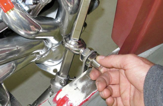
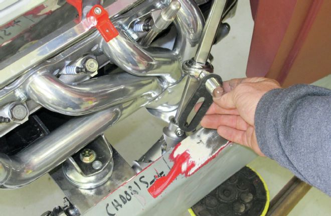
16. All support bearings work with round or DD shafting. Rod end bearings with a 3/4-inch hole size are commonly used for supports. These rod end bearings are supplied with two jam nuts for mounting and are available in steel, stainless steel, and polished stainless steel. In this case a mounting bracket was fashioned to hold the upper support, as shown.
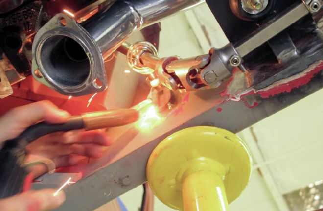
17. With the pickup back up on the lift, the support bracket was welded to the inner portion of the framerail and then the rod end slid over the upper shaft and the support attached to the bracket.
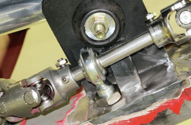
18. A second rod end support was trimmed in length and located on the lower shaft below the motor mount, as shown.
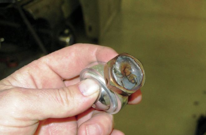
19. In the case of the lower support, one of the rod end nuts was threaded onto the shaft flush with its trimmed shaft and welded in place.
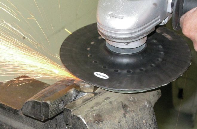
20. The weld was then ground flush with the bottom of the shaft and nut so the assembly would sit flush with the inner wall of the framerail beneath the motor mount.
21. Next the support was tacked in place and will be finish welded to the 'rail to complete the process.
22. This view shows the complete steering setup with the shafts, joints, and support bearings in place. To finish up the job the support will be finish welded and the joint's setscrews tightened (and locking nuts treated to thread locking compound).