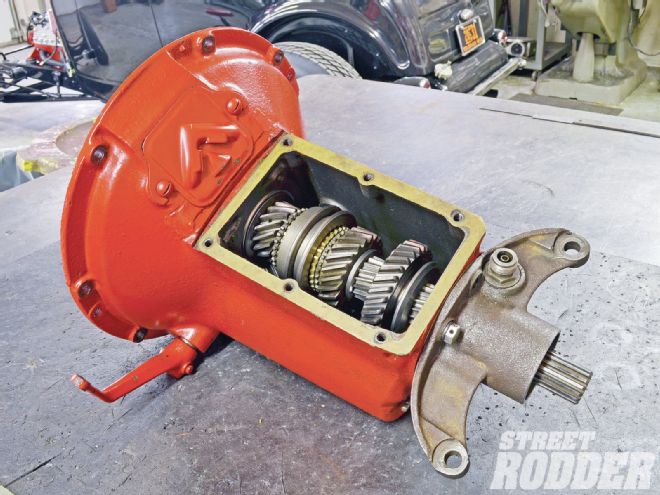
The transmission Ford produced from 1932 to 1950 is metaphorically and physically next to its famed Flathead engine. It never was the strongest option but it more than compensated with abundance; Ford installed a variant of the design in every one of the cars and light trucks it built during those 18 years. And Ford built millions of vehicles during that period.
Two things especially endeared that transmission to enthusiasts. For one, technology developed at a whirlwind pace from 1932 to 1950 and Ford's design bears testimony to that evolution. What's more, Ford's philosophy of incremental improvement means many of the parts interchange. Externally the cases are nearly identical, making it possible to simply replace the crudest 1932 gearbox with the most developed one from a 1948 passenger car. But more importantly, with some gymnastics and fancy language, bits and pieces of the latest versions can be used to update the earliest. That wasn't lost on bucks-down enthusiasts who needed to repair an ailing transmission in a pinch. With nearly two decade's worth of transmissions to choose from, an enthusiast had no excuse but laziness to let a Ford lie derelict because of a broken transmission.
Naturally, fondness for Ford's beloved box waned as technology evolved. But a funny thing happened over the past 20 or so years: The vintage revival made stars of Ford's engines, axles, and of course its faithful gear changers. That reinvigorated popularity in the light of a radically diminished donor pool turned gray iron into gold.
A learning curve accompanies that newfound popularity though. Even if you were born during the hot rod's first golden period chances are you weren't old enough to gather real experience with old Ford transmissions the first time around. We need instruction. Though we're nowhere near the first to do so since the revival's start and we're equally limited to outline a comprehensive account, here's our bid to explain what goes on inside an old Ford gearbox.
You likely recognize our guide. Frank Wallic has a unique combination of traits: He's an amateur like most of us but tackles jobs that would make most professionals blush. He's probably most famous for his rivet work, specifically for the warbird-style seats that he builds. For that reason he usually adopts cheeky names like Rosie the Riveter but we're thinking of referring to him from now on as Fearless for his enthusiasm to tackle projects most enthusiasts consider daunting, if not forbidding.
As part of his roadster's construction, Wallic and his longtime pal and early Ford gearbox guru Ron Keilwitz, ran though an old Ford gearbox. And as usual he documented the progress. Wallic describes the rebuilding process as quite effortless, or at least they make it appear that way. "There's really nothing to these old transmissions," he assures. "They don't require any special tools or techniques." And he's right; the most specialized tool required to rebuild an old Ford transmission is a pair of retaining-ring pliers. Technically bearing installation requires a hydraulic press, "… but you could get the same results by just heating the bearing with a torch and tapping it in place with a pipe," he maintains.
That's not to say this is mindless work. The disassembly process, which we unfortunately can't do justice, requires considerable inspection and judgment. Though tough, these transmissions are still vulnerable to chipped teeth, pitted shafts, wallowed-out shift mechanisms, and outright broken cases, just to name a few. And as a result of the evolution the Ford gearbox underwent, there are near countless variations. Straight-cut First and Reverse gears made way to quieter helical gears. The case grew several times to accommodate various clutches and gear diameters. The shift hubs and forks got wider. At one point Ford divorced the shifter from the case and moved it to the steering column (shift mechanism aside, the rebuild procedure is the same). The tailhousing changed several times to fit various chassis and the driveshaft changed from an enclosed design to a fully exposed one.
And those are the obvious changes. Ford altered the internals subtly over the years. Ford bored its countershaft gear (aka cluster gear) with two diameters over the years. The 1-1/8-inch-diameter bore uses caged bearings and the inch-diameter needle bearing uses free needle bearings. And in some years Ford produced both styles. Ford also offered at least four variations of thrust washers for the rear of the countershaft gear. One had five teeth on its perimeter; the other two staggered pairs. Later transmissions could have either a single thick washer with four raised prongs or two thin washers.
Many parts interchange but they don't do so without the proper corresponding ones. It takes a fair bit of knowledge to understand which parts fit with what, and that's something that we can't cover fully in the space we have. That would literally require a book. And few books rank with the one Mark VanPelt publishes.
More than a rebuild manual, The Ins and Outs of Early Ford Transmissions is a field guide for old Ford transmission components. It outlines the seemingly infinite combinations possible by mixing and matching parts. VanPelt also offers a considerable catalog of replacement parts, which makes it a lot easier to source new bits for old bones. And finally, it does cover the shift tower assembly and side-shift variations that we can't resolve here.
Though we reduced it to its elements the process that follows isn't exactly an oversimplification of the rebuild process. It really is that easy, another thing that endears Ford's old transmission to every generation that discovers it. Rebuild one and you too just may fall in love with one of the most beloved beasts of burden, Ford's early three-speed transmission—Dearborn's donkey.
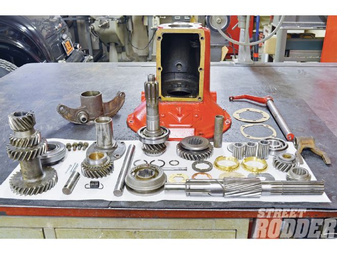 1. Frank Wallic began the reassembly by laying out the parts and conducting an inventory. Inspection should precede this point but it’s a good idea to conduct another inspection, even if only visual.
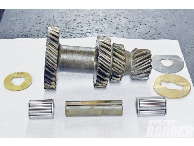 2. The dimpled brass washer fits the front (left) of all countershaft gears (aka cluster gears) from 1932 to 1948, but this two-washer style of rear thrust washers is unique to this particular countershaft. The short caged bearing slides into the front and the long bearing into the rear with the spacer between them.
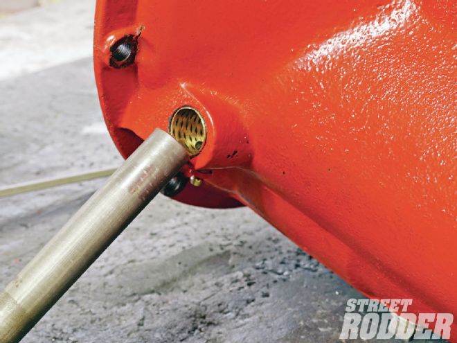
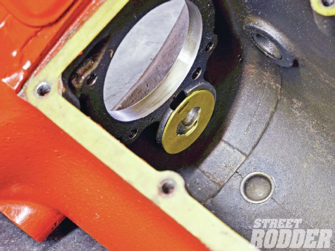 3. The dimple in the brass washer corresponds with a slot in the boss cast in the bellhousing side of the case. A dab of grease temporarily holds it in place.
 4. This washer style fits with the flat brass washer adjacent to the First/Reverse gear and the steel thrust washer between that brass washer and the case. Wallic slid the shaft into the countershaft gear just enough to keep it aligned with its washers in place.
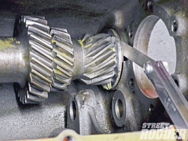 5. With the shaft in place Wallic measured the lash. Wallic says Ford specifies at least 0.007-inch lash and allows for as much as 0.017 inch. Excessive lash indicates a worn case and/or cluster.
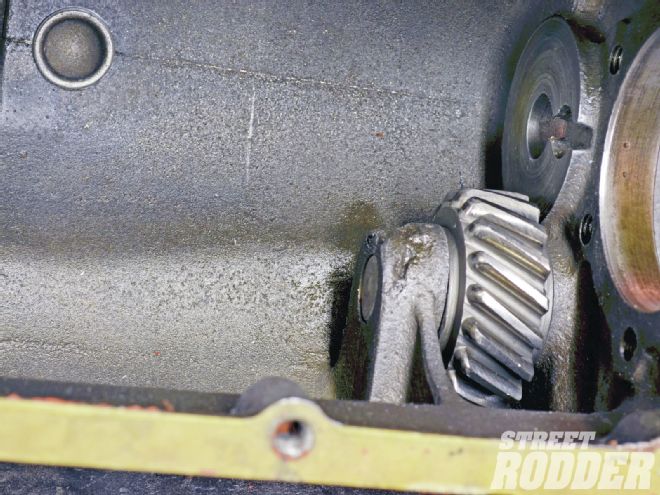 6. After measuring the lash Wallic removed the countershaft and installed the First/Reverse idler with the teeth tapers facing toward the bellhousing. Take care to align the hole near its end with the hole bored into the case.
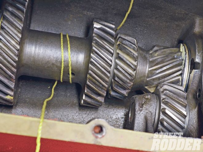 7. Wallic anticipated a following step by wrapping string around the countershaft before dropping it in place, a trick he learned from his pal Ron Keilwitz. He aligned the hole near the end of the countershaft’s shaft with the hole bored in the case.
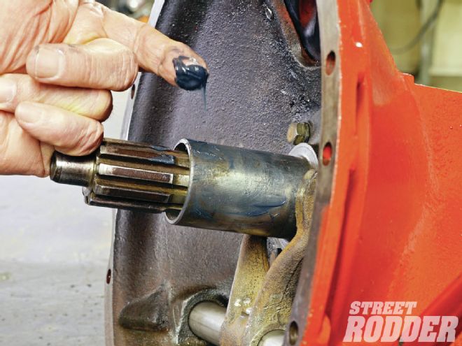
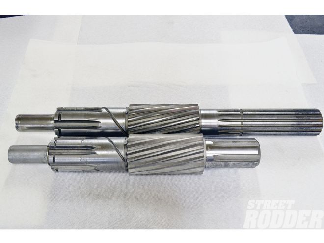 8. He began with the mainshaft. It comes in two flavors: short for closed driveline (foreground) and long for open driveline. They also have a small (0.063-inch or so) pin pressed into a hole at the front end of the spiral gear (photo left).
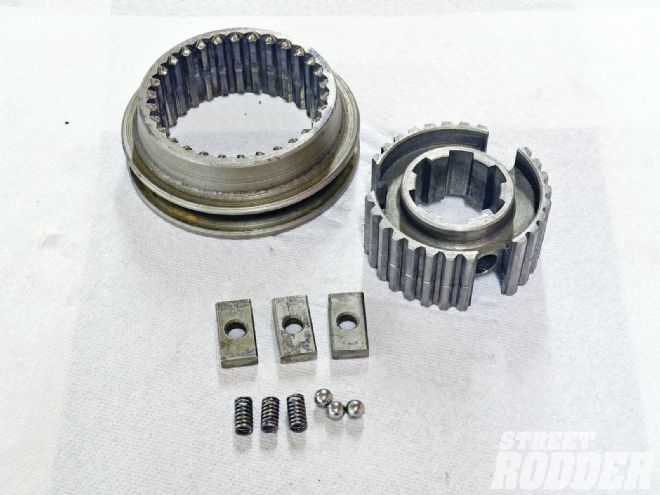 9. Before we continue we need to explain the Second/high-gear clutch assembly. The clutch hub (right) installs on the mainshaft’s straight broach. The slider (left) slips over it. When moved toward the driveshaft by the shift fork the slider locks Second gear to the mainshaft; when moved toward the bellhousing it locks the input shaft to the mainshaft for direct (high) gear. The springs and balls preload the slider and the drilled tabs align the balls.
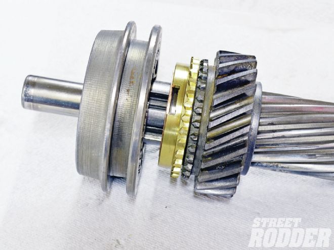
 10. Wallic trial-fit the Second gear stack to the mainshaft. From right to left is a large steel washer; the slot in its ID corresponds with the pin near the main shaft’s spiral gear. Second gear follows that, then a brass washer and the clutch hub. For fitting purposes he forewent the Second gear synchronizer.
 11. This large retaining ring holds the clutch hub and Second gear stack to the mainshaft. It snaps into a groove near the forward (bellhousing) end of the shaft.
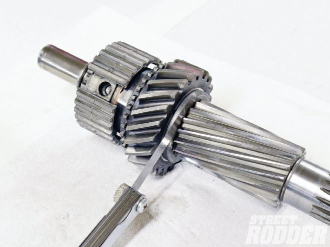 12. Wallic then measured the gear-stack lash. According to Wallic, Ford specifies 0.004- to 0.008-inch lash.
 13. Satisfied with the Second gear stack lash, Wallic removed the retaining ring and clutch hub and installed the brass-synchronizing ring. The radial-grooved cylinder to the left is the Second/high clutch slider installed on the clutch hub with the springs, balls, and tabs in place. Note that its tapered side faces the bellhousing.
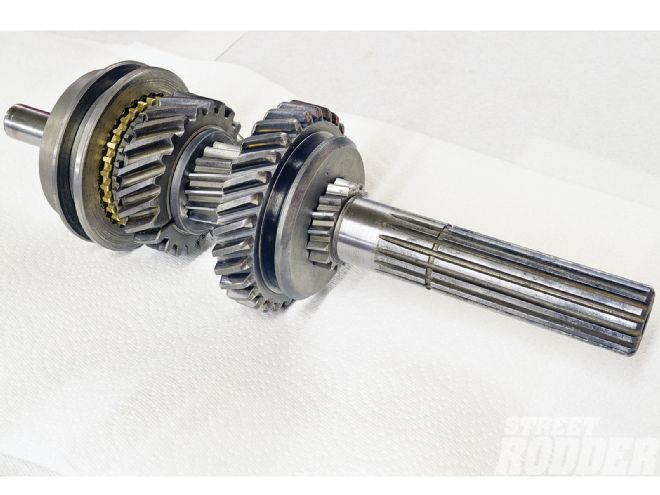 14. The First/Reverse driven gear simply slides onto the spiral-broached part of the mainshaft. The grooved side (for the shift fork) faces the driveshaft end of the shaft (photo right).
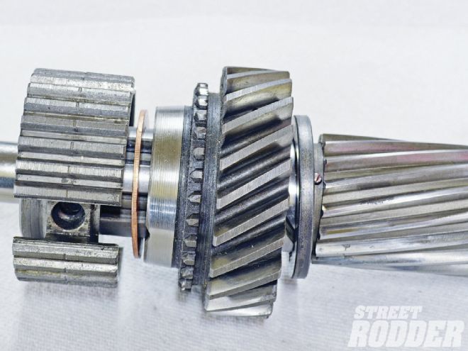
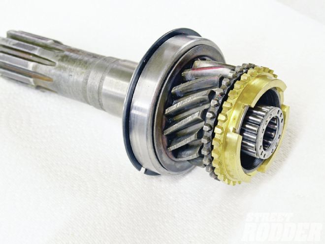 15. Wallic photographed the assembled main drive gear. The broached end to the far left is the input shaft. The large flange is actually a bearing that simply presses onto the shaft. Officially it must be pressed on but heat will expand it enough so a pipe tapped by a hammer will seat it. The brass synchronization ring simply drops on and the short caged bearing slides into the bore in the rearend.
 16. Wallic pushed the countershaft gear’s shaft into the driveshaft end of the case just enough to retain the thrust washers. He did the same thing with a spare shaft at the bellhousing end. At this point the countershaft merely lays on the bottom of the case unsupported by the shafts.
 17. Shift-fork installation would precede this step for side-shift transmissions. Since this is a top-shift model, Wallic just lowered the assembled mainshaft into place.
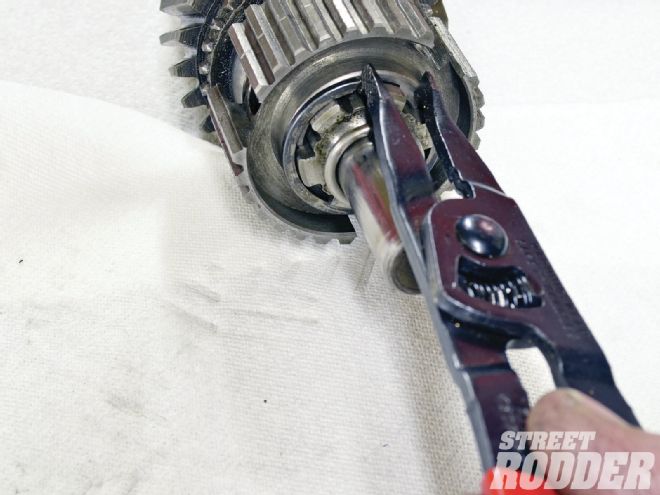
 18. With the mainshaft in place he installed the bearing oil baffle (slinger) and then the mainshaft bearing. Unlike the main-gear bearing it merely slides on. A snap ring near its rear shoulder keeps the bearing from dropping into the case. Note the yellow strings from the countershaft.
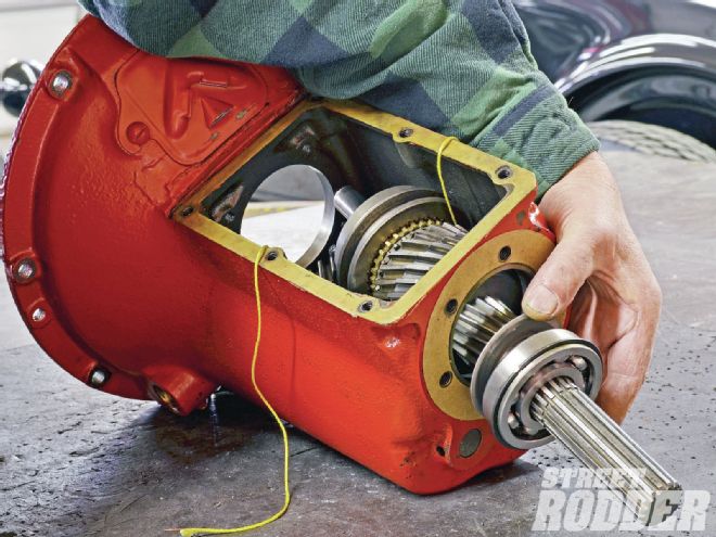
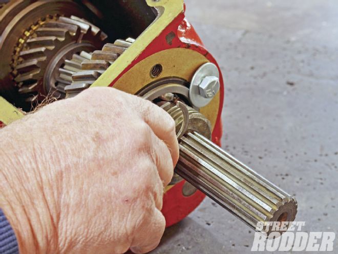
 19. He didn’t show it but prior to this point Wallic pushed the main drive gear into the case’s bellhousing end and assembled it with the mainshaft. What’s important here is that he’s pulling the countershaft up with the string so he can push its shaft in place. That’s the string trick.
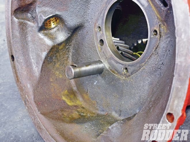
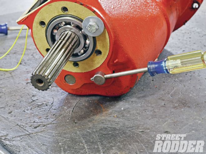
20. The bolt and washer holds the mainshaft bearing in place. At this point the countershaft hangs out about an inch. The screwdriver reveals how the pin locks that shaft and the reverse-idler shaft when the countershaft shaft seats. Alignment is essential.
19. He didn’t show it but prior to this point Wallic pushed the main drive gear into the case’s bellhousing end and assembled it with the mainshaft. What’s important here is that he’s pulling the countershaft up with the string so he can push its shaft in place. That’s the string trick.
20. The bolt and washer holds the mainshaft bearing in place. At this point the countershaft hangs out about an inch. The screwdriver reveals how the pin locks that shaft and the reverse-idler shaft when the countershaft shaft seats. Alignment is essential.
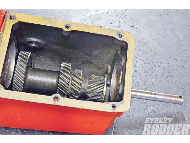
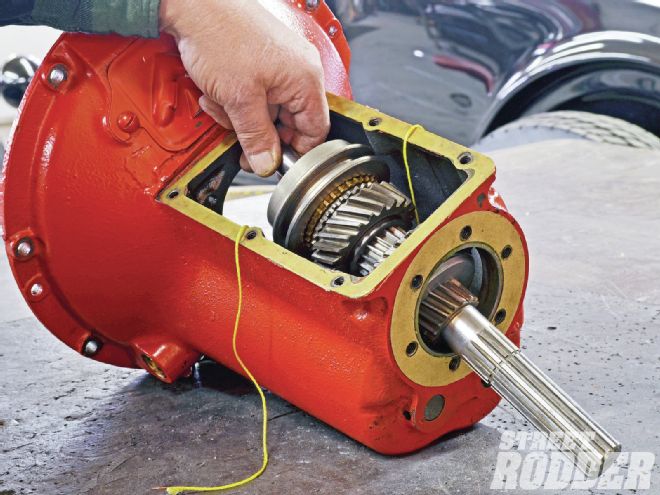
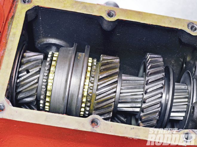
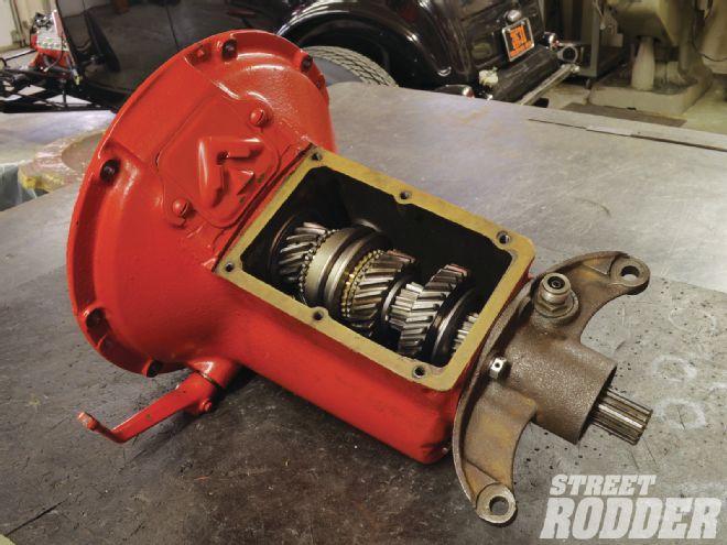
 21. A peek inside the tower opening reveals the assembled main drive gear and mainshaft assemblies with the countershaft in place. This basically concludes the internal assembly portion.
 22. The speedometer-drive gear slides on last followed by a retaining ring (shown inverted here for illustration). The drive gear is part of the driveshaft on closed-drive models.
 23. He didn’t show the process but Wallic installed the cross-shaft bushings in place and reamed them with a brake-cylinder hone to fit the cross shaft. He installed the throwout fork as the shaft emerged through the inside of the bellhousing but before it slid into the yonder side’s bushing.
 24. Wallic didn’t show its installation but the main drive gear bearing retainer prevents the main gear shaft from dropping out of the front of the case. The retainer doubles as a throwout bearing collar. He dabbed a bit of grease on it so the bearing would slide freely.
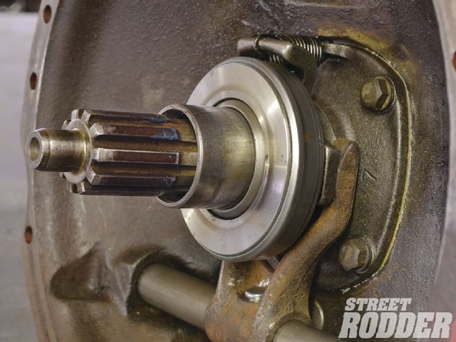 25. A spring pulls the throw-out bearing assembly toward the main drive gear bearing retainer. Also visible is the pin that fastens the throwout fork to the cross shaft. Note that in a pinch a worn cross shaft can be rotated 180 degrees to better fit the bushings.
 26. Finally Wallic installed the cross-shaft arm and replaced the bolt and washer that temporarily held the mainshaft bearing with the tailhousing. The shift tower (not shown) officially completes this sequence.