Forced induction is the only way to get a 1.5L four-cylinder engine to wheeze out as much air as and behave more like a V8 twice its size. Out of the multiple types of forced induction, (supercharging or nitrous), none is as comprehensive as the turbocharger system. The components are many and their ability to harmonize with one another vital to whether or not power is multiplied or oily burrows end up in engine blocks.
In terms of efficiency, no other form of forced induction compares to the turbocharger—and that includes supercharged Top Fuel dragsters that spit out more than 8,000hp from 500 cubic-inch engines. Take mid-1980s turbocharged Formula One cars, for example, that produced a whole lot less power but from smaller engines, resulting in some of the most impressive specific outputs in automotive history. Don’t get excited, though; your hatchback is nothing at all like a mid-1980s Formula One car, but the advantages of a properly engineered turbocharger system mean the same thing: more power, more efficiently.
A naturally aspirated engine banks on how well its internal pumping capabilities are executed as the pistons travel downward to inhale air equal to whatever the environment’s atmospheric pressure is, which is really just a fancy way of describing the force exerted onto you by particles of air that you’ll never see. In between all of those particles of air is all kinds of wasted space, though. Forced induction systems, like turbochargers, compress all of that together, eliminating most of that wasted space to allow more of those air particles inside. More air means more fuel can be burnt, and burnt fuel is what makes horsepower. For all of this to happen, the turbocharger relies on engine exhaust flow to spin its turbine, which, as a result, rotates its opposing side that compresses incoming air. Even though turbochargers don’t feature any of the parasitic losses of superchargers and instead recycle otherwise wasted exhaust gases, it isn’t all bliss; the process generates a whole lot of heat, which increases the chances of you detonating and making a mess of your engine, making everything more complicated than you think it is.


The Turbocharger
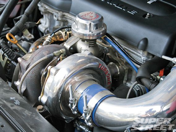
The turbocharger is made up of a compressor housing and compressor wheel, a turbine housing and turbine wheel, a center cartridge that sits in between both housings, a common shaft located inside of the center cartridge that connects both wheels, and a system of bearings that supports the shaft. Air enters the turbocharger’s compressor-side inlet where the already-spinning exhaust wheel on its opposing side transmits rotational forces through the common shaft that’s connected to the compressor wheel that pumps air. After exiting the compressor, the now-dense air charge makes its way into the intake manifold. Meanwhile, exhaust gases exiting the cylinder head continue filling the turbine housing, creating backpressure and heat, which, because of the housing’s unique shape, rotate the turbine wheel and repeat the cycle. As exhaust speed and RPM increase, so does the compressor’s ability to yield more airflow. Although turbochargers reclaim otherwise wasted exhaust gases to operate, the system isn’t entirely efficient; the turbine, which sits directly in the exhaust path, restricts airflow and increases backpressure. It’s a small tradeoff, though, especially once the compressor side’s gains are considered.
 |
| Squashed in between the compressor and turbine housings is the center cartridge, which harbors the common shaft that connects both wheels. Here, high-pressure engine oil feeds the assembly, lubricating the shaft, ensuring that it remains cool and friction-free as rotational speeds as high as 300,000 rpm are often met. Not unlike a crankshaft, the common shaft rests on a film of oil surrounded by journal bearings or more expensive and sophisticated ball bearings. Located on each end of the impeller, the bearings help support the assembly and reduce friction under extreme radial, thrust, and axial loads. The stress placed on the shaft is enormous; after all, even large, slower-spinning turbochargers spin more than ten times faster than the average four-cylinder engine.
 |
| Before selecting a turbocharger, a target power level should be determined. Now is a good time to be honest with yourself; choosing the biggest turbo you can find to make up for the fact that you were habitually picked last in PE class will never end well. Consider what your car will primarily be used for: a track car might be better suited to a smaller, quicker-spooling turbo as opposed to a drag car that only cares about top-end power. Now is also a good time to forget about how much boost you think you need. For example, 20 psi from a Garrett GTX turbocharger is nothing at all like the 20 psi you’d experience from whatever’s underneath the hood of your uncle Hal’s Buick Regal. Horsepower and airflow are all that matters. It’s what wins races and blows up engines.
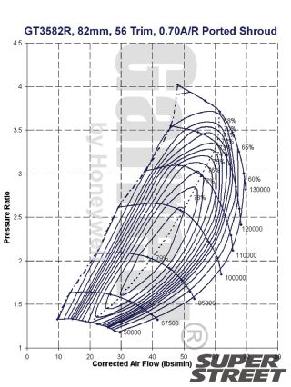
Finally, when selecting compressor and turbine housings, choose ones that can pump the most air into the cylinders but without raising temperatures more than complicated thermodynamics’ laws say they should. Byzantine-looking compressor and turbine maps will reveal a given turbocharger’s efficiency, surge limit, boost potential, and shaft speed but go beyond the scope of this article. The labyrinth of considerations doesn’t end there, though. You’ve also got to look at fancy terms like pressure ratios, compressor surge, trims, and A/R ratios, which also go beyond the bounds of turbocharging basics.
 |
| The Exhaust Manifold
A specialized manifold allows exhaust gases exiting the cylinder head to enter the turbine housing. There are two kinds: log style, like you’d find on OEM applications, and tubular, which are generally handcrafted and feature equal-length runners. Log manifolds are best suited to engine bays where space is at a premium and are generally less expensive; tubular manifolds work well for custom applications or where extracting every last bit of power is important. No matter the type, an exhaust manifold’s design directly affects performance. A proper design ensures that exhaust gas velocity remains as powerful as possible in order to effectively spin the turbine wheel. Restrictive or excessive bends as well as improperly sized or unequal-length tubing can all negatively affect power.
One of few options to consider when purchasing an exhaust manifold is the divided-entry option, which is compatible with twin-scroll turbochargers that separate individual cylinders’ exhaust pulses that would normally interfere with one another. For example, a four-cylinder engine with a 1-3-4-2 firing order where its number-one cylinder opens its exhaust valves while its number-two cylinder’s exhaust valves are beginning to close can lead to contamination within the number-two cylinder. It also robs exhaust gases that would otherwise be used to spin the turbocharger. Divided housings group complementary cylinders together for better boost response and decreased cross-contamination.
 |
|  |
| The Wastegate
Since boost pressure rises as exhaust gas velocity and engine speed increase, regulating it once the system is up and running is crucial. The wastegate takes care of all of this so that a given pressure and horsepower level is never exceeded. Wastegates can be integrated externally into the exhaust manifold or internally into the turbine housing, like in OEM applications. The goal is the same either way—to divert exhaust gases away from the turbine wheel once a preset boost level has been reached. With internal applications, a pneumatic actuator opens a flapper valve built into the turbine housing once the pre-set boost level has been reached. When opened, exhaust gases are directed away from the turbine and into the exhaust stream, after the turbocharger, causing the turbine wheel to slow down. External wastegates are integrated directly into the exhaust manifold and are generally more effective. They feature large, stainless steel poppet valves that are held shut by pre-calibrated springs. Once boost pressure overcomes the wastegate’s spring pressure based upon a signal sent by any boost source, the spring compresses, opening the valve. External wastegates divert exhaust gases back into the exhaust stream after the turbocharger or into the atmosphere. Before selecting a wastegate, consider its valve size and spring pressure, which determine how much flow it can bypass and how much boost it can regulate, respectively.
 | Internal wastegates feature pre-set diaphragms that regulate boost by opening and closing a flapper valve controlled by a swing arm. When the valve opens, exhaust gases bypass the turbine wheel, stabilizing boost.
 |
| The Boost Controller
Boost controllers do little more than allow boost pressure that the wastegate would otherwise recognize and act upon through its signal line to escape into the atmosphere or back into the intake stream, delaying its opening and increasing boost pressure within the system. There are two types of boost controllers: manual and electronic. All boost controllers do the same thing, though, which is to fool the wastegate. Early manual boost controllers were nothing more than bleeder valves that released boost pressure at the wastegate’s signal line to prolong its opening. More advanced manual boost controllers work much like an air compressor’s regulator, where tension is applied to a spring-loaded ball that, until unseated by a pre-set amount of boost pressure, prevents the wastegate’s valve from opening. Electronic systems operate similarly but use solenoids or stepper motors instead of regulator-like devices. An electronic control unit monitors the engine’s boost level and uses a solenoid to counteract whatever the wastegate’s spring pressure would normally allow.
The Intercooler
Like a radiator, an intercooler is a heat exchanger located in between the turbocharger and throttle body, which reduces the intake air temperature that’s been heated up following the turbocharger’s compression process. Although not mandatory on all turbocharged applications, intercoolers allow for increased compression ratios, more aggressive ignition timing, higher boost, and reduced chances of detonation. There are two types of intercooler cores: bar-and-plate and tube-and-fin. Bar-and-plate intercoolers are generally more effective than tube-and-fin designs and allow for improved airflow. Here, the intake tube sits flush against the core, reducing turbulence for uninterrupted flow. Despite all of that, tube-and-fin designs are still popular because of their lower cost and lighter weight.
There are also two types of intercooler configurations: air-to-air and liquid-to-air. Air-to-air intercoolers, like radiators, rely on outside air to pass through their fins, cooling the separate tubes that contain the incoming intake charge. Instead of outside air, liquid-to-air intercoolers rely on self-contained water supplies and can be mounted just about any place. Such systems are typically suited for drag racing applications where an ice water mixture can be added that need only remain cold for a few minutes. Liquid-to-air intercoolers are also not as efficient as air-to-air systems at higher speeds. No matter the type, no intercooler is perfect. Since the air charge is passing through its restrictive shape, boost pressure losses are common. The extent of the pressure loss depends on the quality of the intercooler, and in the case of a sound intercooler, the increased air density is almost always worth the tradeoff.
 |
|  |
| The Blow-Off Valve
Like the wastegate, the blow-off valve diverts boost pressure out of the system. Unlike the wastegate, though, the blow-off valve does so from the intake stream. Installed between the turbocharger’s compressor and throttle body, the one-way diverter valve relieves pent-up boost pressure in the system once the throttle’s been closed. Once shut, airflow quickly stops, causing extreme pressure changes, which can lead to compressor surge and eventual turbocharger damage. A boost pressure signal traversing from the intake manifold alerts the blow-off valve once the throttle has been closed, releasing pressure into the atmosphere. Blow-off valves are offered in a variety of materials, including aluminum and ceramic, with various mounting options. For higher-boost applications, consider aluminum valves that feature secure mounting options.
 |
| All The Other Good Stuff
A well-equipped turbo system doesn’t end here. When adding significant amounts of power, each of an engine’s systems are affected. First, additional power will never be made without additional fuel. Larger injectors, a higher-flowing fuel pump and an ECU that’s able to control all of it are mandatory. Second, whatever additional power you’ve added won’t last long if the engine isn’t strengthened. Forged pistons and connecting rods as well as stronger head studs are almost always required when significant power gains are expected and, depending on your platform, ductile iron sleeves, stainless steel valves and stiffer valve springs that can counteract the newfound positive pressure in the combustion chamber will also be likely. Finally, the largest exhaust system that you can fit (and bear the sound of) will only make your turbo system more efficient.
 |
|