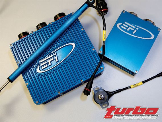
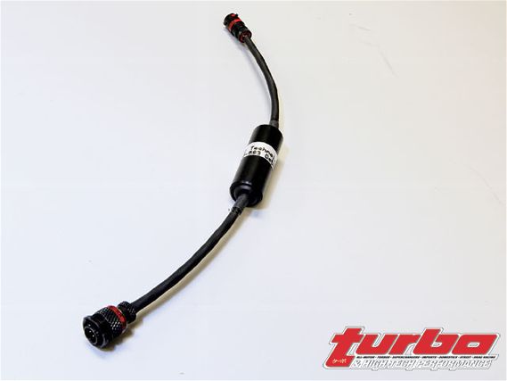
 | EFI Technology Level 2 and Level 4 Loggers with a Linear Potentiometer and Rotary Potentiometer.
Data acquisition is employed in almost every type of modern-day racing vehicle. The question is why? What are the advantages, disadvantages, and misconceptions of this technological mess of wires and circuits? In this segment we'll discuss components and hardware (the logger itself, sensors, dash displays, and harnessing).
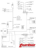
The Logger Control Unit (LCU) is the heart of the data acquisition systems and, in some instances, it's integral with the dash display unit. The purpose of the LCU is to acquire data and store it through means of complicated circuitry and smoke (the magic stuff that makes electronics work). Image six illustrates a typical layout to give you an idea of how the system works.
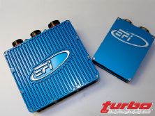
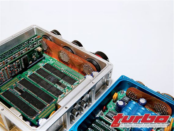 | Here's the EFI Technology Level 2 and Level 4 Loggers showing off their internals.
As you can see, a central unit has all the sensors connected to it. This LCU provides power (5, 12, and 20-plus volts) and ground, and then monitors the change in the sensors to produce data. A variety of sensors-shock potentiometers, strain gauges, rotary steering pots, pressure sensors, laser ride height, temperatures, IR temperatures, and more-can be utilized. Any sensor with a 0- to 5-volt output can typically be used; we'll look a bit later at the requirements of sensors and how they relate to the LCU.
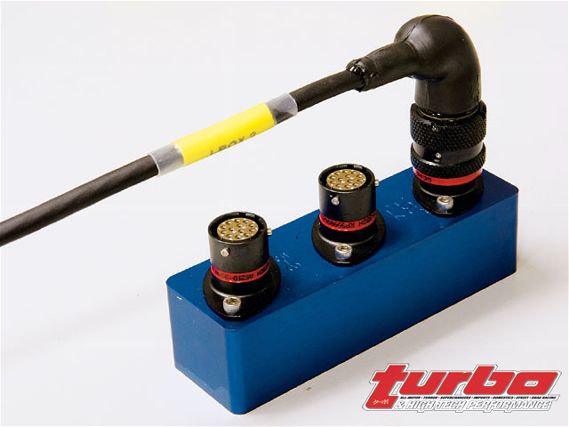
More complex layouts and installations are available. These types will typically employ remote modules, which are responsible for supplying power and ground sensor amplification, if necessary, and a data stream output back to the central unit. A typical installation of this type is shown in image 4.
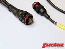
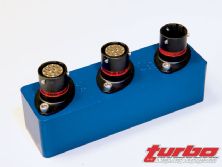
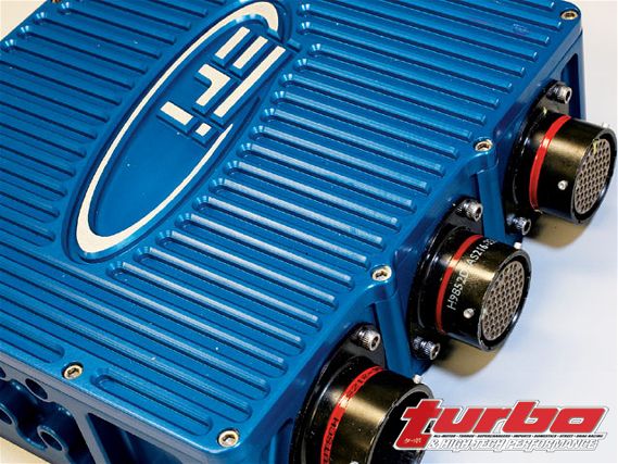 | EFI Technology Level 4 Logger with Autosport Connectors
The LCU typically consists of a few main components, a processor, and main board that reads the data (other higher-end units use dual processors to accomplish other tasks). A power supply runs the sensors, dash display, and other related ancillaries. A built-in or external memory system records data, using some type of communications interface (serial, USB, CAN, Ethernet, wireless) downloading data, and sending it to a different configuration. Most high-end data systems also have an interface to receive data from third-party systems, such as tire pressure monitoring, ECUs, GPS, and more. As of late, sending data over a CAN stream allows the system to be expanded to an almost limitless capacity.
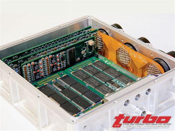 | EFI Technology Level 4 Logger Internals: memory boards, comms, and analog cards
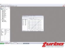
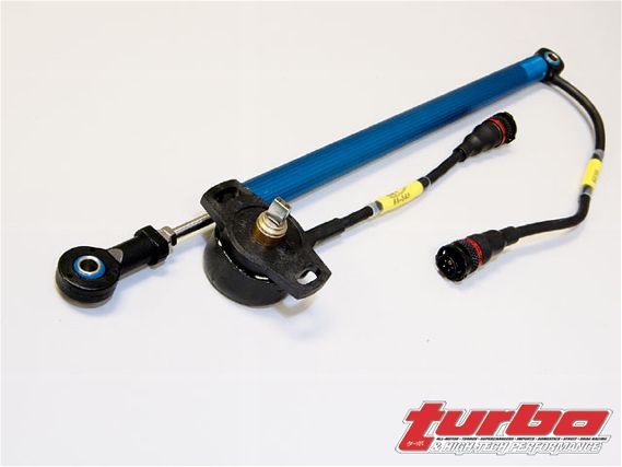
Let's now discuss sensors, typical sensors on racings cars, and cars in general that have a 5-volt supply, a signal 0- to 5-volt analog, and a ground. The most common sensor added to a road race car is a linear potentiometer. This is used to measure shock travel and shock velocity, if onboard, or post process math is available. As mentioned before, to make this sensor work it needs three things: 5-volt input, ground, and an analog 0- to 5-volt output to the LCU. As you move the sensor through its range of travel it will produce an output voltage. The LCU will need to be programmed with a calibration to convert this voltage value into an engineering value. A calibration for a rotary suspension pot is shown on image 11.
Other common 0- to 5-volt sensors include rotary potentiometers, which can be used for: gear position, shock travel, steering position, throttle position, and more.
A string potentiometer can also measure a variety of things. Its fragile nature, however, usually makes them inadequate in a race car.
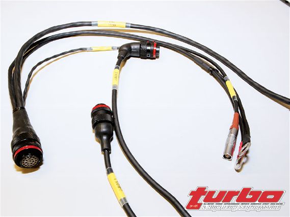 | The Data System Harness features Autosport connectors, epoxied shrink boots, and NTFR sleeving for maximum reliability.
Strain gauges and load cells require amplified circuitry to be measured correctly. This can be accomplished using internal amplifiers inside the LCU, inline amplifiers, and amplifiers inside of the remote junction modules. However, there's a downfall to including them inside the LCU; an amplified circuit, no matter how well it's designed, is going to induce noise into the rest of the circuits. This can skew your data and perhaps misrepresent trends and cause a number of other problems, while it can be done it's not recommended. On some installations this is critical and either of the above methods will alleviate this problem. Strain gauges and load cells are typically used to measure suspension loads, initiate shift cuts, and other applied force measurements.
 | EFI Technology strain gauge/load cell amplifier used to reduce electrical noise, completely configurable per application
Thermocouples, whether infrared or contact type, will need to have amplifiers in order to work. It's also recommended that these be done external of the logger to reduce noise in the system.
There are some odd sensors used on race cars that may require +/-15-, 10-, and 20-plus-volt power supplies. While these are few and far between at the top levels of racing, it's mandatory to accommodate any and all sensors a team may require. Loggers should also have a variety of differential inputs available.
While voltage values work fine for simple observation and testing, computers aren't designed to work in that fashion. As the voltage value comes into the LCU it's then converted into a Bit value. What is a bit? A bit is a value that the logger can interpret into an engineering value and depending on the resolution, the accuracy of the sensor will vary. A good data acquisition system will have a 12-bit resolution-16-bit is available but isn't advantageous for reasons we'll discuss. Lower-end products or engine control systems typically have 10-bit inputs.
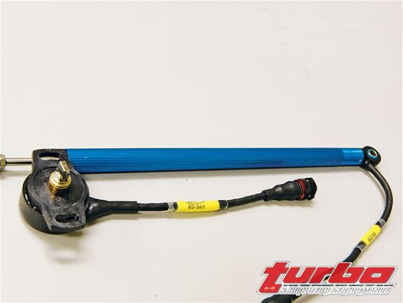 | Linear Potentiometer and Rotary Potentiometer used to measure positional change.
Let's Break Down The Bit Values:
Why not use the highest bit value available? In theory this would be great because at the proper acquisition rate, you'd receive the most accurate data available. However, theory isn't always true in practice and that's where we run into the problem.
Electrical systems are extremely noise sensitive, especially in a race car environment where you have items with huge current draw and other generally noisy electronics-radios, telemetry, ignition coils, and alternators. If you induce as much as 0.1 volt of noise on a 16-bit system, you'll receive around 1,300 bits of engineering value change that will skew your data. It's commonly accepted that a 12-bit system will offer the best compromise between noise/true data exchange. We'll discuss some solutions that aid in noise reduction when we reach the wiring/harnessing area of this discussion.
 | Data Acquisition EFI Technology Logger
Dash displays flash lights and gizmos, all in the hope that the driver will actually look at it and tell you there's something wrong with the car. Examples of different dash displays include a standard LCD-type display with a shift light/gear position indicator. An LED steering wheel dash is also typically used in open wheel cars or prototypes. Dash displays are a fairly straightforward subject. Find a type you like that has a versatile setup, mount it in the car and go! Most displays contain four or more data fields, a message center, multiple warning lamps, and multiple pages to display different setups at the push of a button. When picking a dash display, realize its only function is to display data to the driver. With this in mind, you'll need to consult with your driver, and configure its settings to his or her preference. As with any race event there'll usually be separate pages for practice, race, and qualifying. As all of these sessions have different goals, different data will need to be displayed to make these easier to ascertain.
 | Data Acquisition EFI Technology Logger
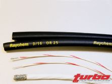
Proper harnessing is both an art and one of the most time consuming, pain in the ass things to do. It's not cheap or fun (well, some might think so), but in the end it's all worth it. Proper harnessing starts with proper wire, proper wire isn't what you get from Manny, Moe, and Jack. Wire will be of a multiple conductor type, that meets the following specs. Now, I know what you're thinking: "This stuff must be expensive right?" Wrong. Proper wire isn't very expensive. The typical recommended brand is Raychem Spec 44, or Spec 55 wire. Spec 44 and 55 wire is well insulated, lightweight, extremely durable, takes heat well, and consistent.
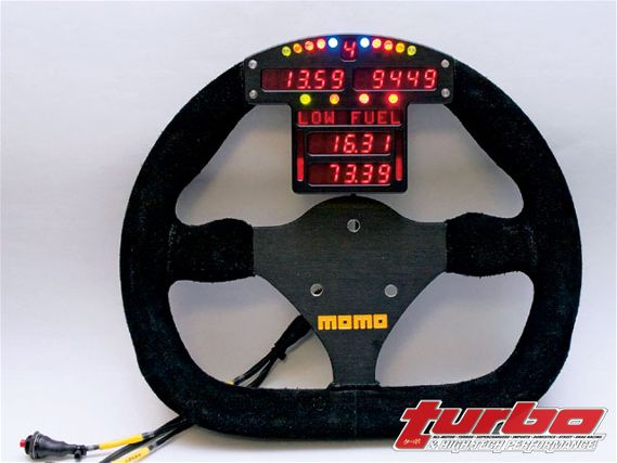 | The EFI Technology steering wheel dash has a message center and configurable shift, and warning lamps.
With your wire taken care of let's move onto the sleeving or covering of the wire. A large variety of brands are available; in fact, there's a huge amount to choose from. The two most common are Raychem NTFR and Raychem DR-25. There are a lot of misinformed customers out there who wholeheartedly believe if it doesn't have the silly yellow Raychem writing on it then it's not good sleeving. This is far from the truth, while Raychem's NTFR sleeving doesn't have pretty writing on it, it has superior abrasion resistance, slightly less heat resistance, but it costs quite a bit less. Either one is perfect for a race car harness. All connectors should be properly booted and epoxyed-no sense in sleeving a harness and then leaving it open where it's terminated.
Let's talk about terminating a harness. While some connectors you might be forced to use attach to the manufacturers component, there are some options.
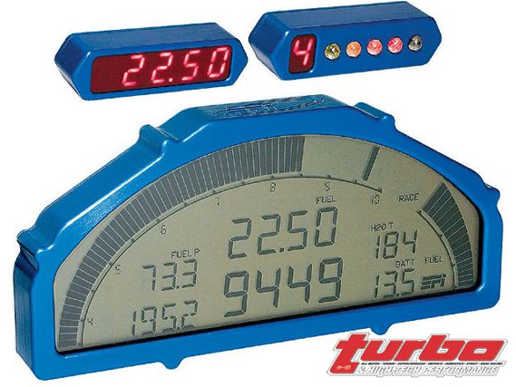 | The EFI Technology LCD dash has with satellite modules used for shift lights, gear position, and extra fields.
Mil-spec connectors offer a great compromise for durability, serviceability, and cost. It's the choice that all the JDM boys use on their hard-parking firewall mobiles. Mil-spec connectors feature pin-type contacts that are easy to crimp, install, and remove. Best of all, they can be crimped solder-free. What's the point of adding a mil-spec connector if it just terminates to a factory connector on the other end?
Autosport connectors are any data acquisition/race car guy's dream. The connectors are known for their cool black anodized, lightweight aluminum housings and super-high density. They are your ultimate connection solution. While almost twice the price of mil-spec connectors, these are the best.
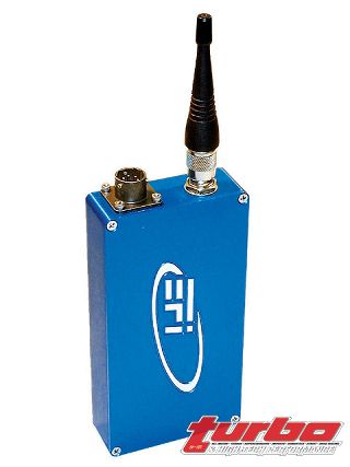 | EFI Telemetry radio can send information back to the pits while the car is on the track, reducing setup time and providing early warnings.
DTM connectors are probably the absolute best-bang-for-your-buck solution on the market. These connectors are cheap and easy to work with, and the best part of all is that they use mil-spec pins, which saves the crimp and solder time. They come in a large variety of configurations, including PCB mount.
Here are a few things to keep in mind when designing a data acquisition system:Design for the future. This usually doesn't cost more and will save you a huge amount of work down the road.
Design for ease of expandability. Be sure to always design an expandable system; you don't want to be ripping into a harness mid season looking for open channels.
Design for serviceability. When designing a system, keep in mind that it may need to be removed from the car for troubleshooting. Don't design some technological masterpiece that requires the car to be disassembled.
In our next installment, we'll visit the software part of our series and show you the power of data acquisition.
10-bit
0-1,024 bits
4.88mV per bit
This equates that for every 4.88mV change in the sensor output the logger will register 1 bit of engineering value change.
12-bit
0-4,096 bits
1.22mV per bit
This equates that for every 1.22mV change in the sensor output the logger will register 1 bit of engineering value change.
16-bit
0-65,653 bits
0.076mV per bit
This equates that for every 0.076mV change in the sensor output the logger will register 1 bit of engineering value change.