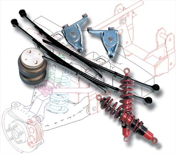
Suspensions have two major functions: One, to support the weight of the truck, and two, to absorb the inconsistencies of the road and terrain changes — which doesn’t sound too complicated — but appreciate that you still want your teeth to remain intact when you hit a pothole, or be able to run down a Vette in the canyon.
Today’s suspensions are, for the most part, still a simple concept. In fact, we still use the leaf spring and shackle design today. On the earliest trucks (up until the late ’50s) leaf springs were used at both front and rear, just like the stage coaches of the Wild West. The IFS (independent front suspension) arrived on the scene in the ’60s. This system allowed for a much more comfortable ride, and better handling through corners.
The IFS allows the two front wheels to travel independently of one another using upper and lower control arms, coil springs, and shock absorbers to control the vertical travel of the front suspension. The front and rear suspensions must work hand in hand. This is because the action in the front suspension will instantaneously effect the rear suspension, and vise versa. Believe it or not, the chassis is just a link between the front and rear suspensions. When accelerating, braking, turning, or decelerating a vehicle’s suspension is affected in many ways. As the vehicle accelerates, the static weight is transferred to the rear wheels and suspension. When entering a left-hand corner, most of the time the vehicle is decelerating while cornering. In doing so, its weight is transferred to the right side of the vehicle, loading the shocks, springs, and sway bar, and unloading the suspension on the left side, making the left side comparatively light.
Just as important to suspension adjustment is the tuning on the chassis. Understanding how modifications to a vehicle’s structural systems improve traction will help us to keep one thing in mind: Power produced by the engine must take a direct path to planting the tires and launching the vehicle forward. Any power absorbed by the undercarriage is power that can’t be used in getting you to the finish line as quickly as possible. The major strength of a truck’s suspension comes from its springs. The springs support the vehicle’s weight on all four-corners. They’re also responsible for controlling the suspension’s travel as it follows the contour of the terrain — be it pavement or mud pit — whether positive (down) or negative (up). Springs also help suspend the frame during a variety of driving conditions, such as acceleration, braking, cornering, variances in payload capacity, or abrupt terrain changes.
There are several types of springs, used in conjunction with one another,that make up your truck’s suspension. It’s very important that the springs comprising the truck’s suspended strength are compatible with one another, whether they be coils, leaves, or air springs. Controlling the deflection and reflection of the springs on all four corners of your vehicle’s suspension will also be a major factor in its handling performance and driveability.
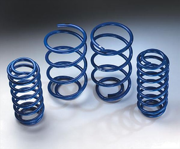
Coil Springs
A coil spring is constructed from round bar stock (wire that’s wound or coiled via either a hot or a cold procedure). A cold wound spring is formed by an ambient temperature winding method, performed on a CNC machine. Then the spring is tempered in a furnace, shot-peened, end ground, preset for fatigue resistance, phosphate treated, and finally powdercoated for corrosion protection. The thickness of the round bar stock combined with the amount of coils in each unit will determine the strength and rigidity of the coil spring. Winding is additionally a crucial segment of the coil spring process, since the distance between coils will dictate the spring rate. Progressive coil springs will have a shorter distance at the beginning of the spring (known as the tender portion) — the transitional part of the spring, which controls the static load as it proceeds into the active load, progressively becoming greater as the spring compresses, growing stiffer in the process.
Spring load and spring rate are often misinterpreted. When we refer to spring load we mean the amount of weight that will compress the spring to a specific height, translated in pounds. Spring rate is the amount of weight needed to compress the spring one inch, and is expressed in inch-pounds (in-lb). Remember: The spring rate will not change during the compression of the spring, but the spring load will.
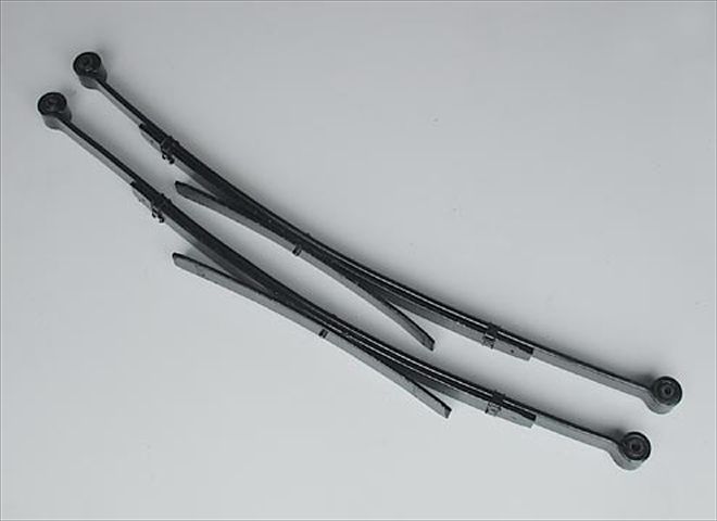
Leaf Springs
These units are constructed of flat bar stock, which derives both strength and flexibility from its tapered thickness. The stock is arched to create additional strength, as well as recoil action. To develop increased strength to the suspension, additional leaves can be added (stacked). Most Leaf Springs are made of SAE 5160 alloy steel. Following selection from the rack, this material is cut to the proper length for its specific application. The ends of the leaves are then drawn and either rolled or tapered, providing easier flexibility and a smoother ride.
Once the eyes are formed on the main spring, it is rolled and cupped at the ends. The holes are then punched for the stacking pin. The unit is now ready for forming and heat-treating. For the spring to be formed and heat-treated, the spring is heated in a thermostatically controlled furnace and then hand-fitted to the proper shape, or free arch. To ensure a permanent arch to the spring plate, the unit is submerged in a hot oil bath. Coilovers
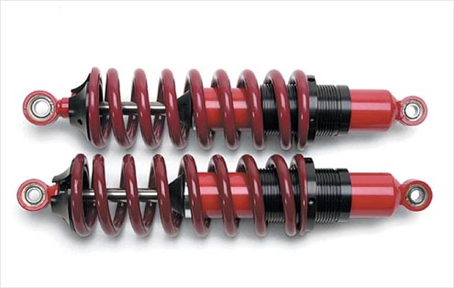
A coilover spring is used in conjunction with a shock, running through the center of the coil spring. The spring is then contained by two collars: one at each end of the shock (top and bottom). The adjusting collar, at the top or bottom of the shock, is thread-ed (along with the shock tube), while the other collar is fixed. By loosening or tightening the threaded collar, the ride height and spring load can be adjusted.
Coilover shocks can be utilized for both front and rear applications. Using coilovers in the rear eliminates the need for leaf springs, which sometimes hinder tire clearances when fatter-than-stock rubber is installed. Coilover shocks can be installed inboard in the rear, meaning they’re mounted inside the frame rails, allowing for the wider tire (pro-street).
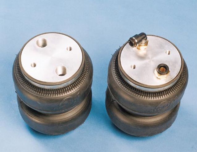
Air Springs or Airbags
One of the newer components on the market, Airbags or Air springs, are used as a direct replacement for coil springs, or as a load-assisting device. There are two components that make up a ’bag: the Cap and the Bellows. The cap is constructed either from steel or from billet aluminum, with ports ranging from 3/8- to 3/4-inch for air intake. The bellows is constructed by combining varying thicknesses of rubber with high-strength fabric in either a tapered sleeve or convoluted design. Numerous styles, sizes, and capacity ratings are available. Air springs function via parameters allowing their maximally efficient operation. These parameters are design, height, stroke, and load. The air pressure in each airspring varies your load capacity and ride height.
Sway Bars
How many times have you been motoring along and it feels like you’re navigating a sponge? While driving, we transmit inputs and demands, including acceleration, deceleration, turning, and braking. Every time we turn into a corner, the truck begins to lean laterally in the opposite direction of the turn. As the corner tightens its radius, this lean becomes more progressive. The physical weight of the vehicle wants to continue travelling in a straight line. As it turns into the corner, the centrifugal force shifts the weight onto the outside tires — the opposite of the truck’s turning direction .
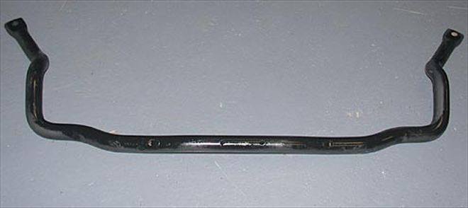
The best way to cure this body roll (roll angle) is to install Sway Bars, both front and rear. The effectiveness of a sway bar depends on its length, as well as its diameter. The longer the swing arm length, the less force the bar can provide with the same amount of movement at its ends. A swing arm with a 6-inch arm length will produce more torsional strength and resistance than a swing arm with a 12-inch arm length: The shorter the arm’s swing, the stiffer the sway bar. Another major contributing factor is the sway bar’s diameter, since material girth mass equals strength. Additionally, the total arm stiffness of a sway bar depends on the rigidity of the frame-mounting surface, as well as the arm’s end links.
When installing your sway bar, its important that it be mounted with the arms parallel to the ground, with the suspension loaded. As the truck turns to the left, the weight is transferred from a neutral load distribution, loading the right swing arm portion of the sway bar, while simultaneously unloading the left swing arm portion. This action is like ringing out a towel: The sway bar’s twisting action is loading in one direction of rotation and unloading in the other. In other words, the sway bar’s swing arm portions are twisting in opposite directions of each other. This is all transmitted by the sway bar end links, connected at the ends of the swing arms by u-brackets with bolts and urethane bushings, allowing them to pivot. The other ends are bolted to your truck’s frame. Shocks
The purpose of Shock Absorbers is to control the compression and extension (oscillation) — of a vehicle’s suspension after hitting a bump or a pothole. To control oscillation in the absence of shocks, the suspension would have to rely on the springs, which have limited oscillative control. If the shocks don’t create enough resistance, the springs will move the suspension too quickly, allowing violently under-damped motion. Too much oscillation, in other words, will cause your suspension to buck like a mechanical bull. If the shocks create too much resistance, however, the motion will be over-damped. Extra-firm shocks have the same negative effect as extra-stiff springs: Your tires cannot consistently follow the contours of the terrain’s surface.
Besides damping, shocks also decrease vibrations and absorb wheel impact. The time it takes for shocks to normalize when travelling over bumps and potholes is referred to as Rebound. Suspension Frequency is the amount of up-and-down strokes a suspension encounters between impact and rebound. For optimal ride and handling, low frequency numbers are desirable. But remember: A frequency number of zero means your body is absorbing the totality of the impact. Can everybody say pelvic fracture? Obviously, proper damping is important.
A basic shock absorber consists of a canister (body), a shaft, and a piston.The piston is attached to the shaft that travels up and down inside the body. To hasten rebound, the shock body is filled with either hydraulic fluid (a petroleum-based oil) or a mixture of hydraulic fluid and gaseous nitrogen (helps dissipate heat build-up due to friction, which may cause foaming, or cavitation — not a pretty thing).
For those of you thinking of raising or lowering your vehicles, please keep the following in mind: When your suspension is dropped, the amount of travel within your shocks decreases. This means you have to either install shorter shocks or add extensions. When lifting your truck, you’ll need to purchase longer shocks with greater throw to compensate for the additional travel.
Weight Transfer and Wheelhop
As performance-minded gearheads, we’re always striving to achieve the maximum horsepower from our engines. Whether it’s an external or internal component, if it improves dependability and horsepower, we’ve gotta have it! But, by creating an ungodly amount of horsepower, we still need to get it to the rear wheels, (where it should be). The more we understand the relationship between engine horsepower, driveline, chassis, and suspension systems, the more we can improve not only the engine horsepower but also the handling horsepower of our vehicles. Our main concern in handling horsepower is that of weight transfer. Under acceleration forward, the static weight is transferred to the rear of the vehicle and rear wheels. The front end of the vehicle will become much lighter. We must take the horsepower being exerted to the rearend and transfer it to the rear wheels without the tires burning off.
One of the most common problems with ill traction is something that most of us have experienced first hand: that joyful phenomenon known as Wheel Hop. The best way to cure this problem is to first understand it. When we mash the throttle, the engine’s horsepower is instantly delivered to the differential. As the horsepower and rpm rise, the driveshaft rotates the differential yoke, which turns to the pinion gear. As the pinion gear rotates, it attempts to climb the ring gear. During this sudden exertion of torque and power the entire rear axle housing is caused to spin backwards, in a counter-clockwise direction. This will cause the leaf springs to distort, which warps the driveshaft’s U-joint out of alignment. During this spring reaction, the suspension is unloaded. This, in turn causes wheelhop. Under a torque load, the axlehousing is allowed to continue to rotate until it meets resistance from the rear leaf springs, which bend and flex into an S-shape trying to snap the axle housing back to its original position. As the power is increased to the differential, the housing is again allowed to rotate back against the springs, the action/reaction of the suspension continuing like a tug of war. During wheelhop, the tires contact patch or traction is lost.
Slapper and Ladder Bars
In the sixties Bill “Grumpy” Jenkins developed the bolt-on slapper bar. This devise helps cure wheel hop. The slapper bar replaces the stock leaf spring pad and is clamped to the rear axle housing. The forward end of the bar is suspended just below the leaf spring eye. When the rear end axle housing begins to rotate during rapid acceleration (launch), the bar also rotates until it contacts (slaps) the leaf spring. The contact area should be directly underneath the leaf spring’s eye, this will eliminate any leaf spring damage. When contact is made with the slapper bar and leaf springeye surface, the bar acts as a lever, taking the energy of the counter-rotation and using it to plant the rear tires into the asphalt. The more rpm, the more leverage strength.
A ladder bar is another traction enhancement device, it serves as an extremely rigid, bridge-type truss which locates the rear axlehousing directly to the chassis. Since the axlehousing is held firmly in place, when torque is applied to the differential, it’s transferred immediately into the ladder bars and the chassis. When using a ladder bar setup to carry power to the chassis, the frontend reacts by rising. This creates rapid weight-transfer, which plants the rear tires, accelerating the vehicle forward
Spindles
Spindles are a cast piece of steel with a machined spud sticking out, upon which the wheel hub and bearings ride. They bolt between the upper and lower control arms and provide a place to mount the brakes and wheels. You can raise or lower your truck with the spindle. Many companies manufacture lift or lowered type units, which, by moving the spud in relation to the center (distance between the ball joint mounts), change ride height. If the spud is moved up it will produce a lower ride height and if it’s lowered the truck will go up. Raising or lowering with spindles will retain proper suspension geometry, so if you’re looking for a couple of inches this could be the starting point. The only issue you might come in contact with on an aftermarket spindle is rim interference. When the spud is moved, the rotating assembly will get closer to the rim. In cases such as this, a larger-diameter rim and tire combo will be needed.
Control Arms (A-arms)
Control or A-arms are a triangular-shaped component used to hook the suspension to the chassis and allow it to pivot. They are made of stamped steel or cast aluminum (stock) or fabricated from steel tubing. Aftermarket A-arms are used to either raise or lower a vehicle and maintain the ability to have your vehicle aligned, by correcting ball joint geometry.