Adding to our 2008 Ford F-250's bulletproofed 6.4L bottom end (assembled in “International Threat Part 2,”), we’re finishing up the Ford Power Stroke’s long-block modifications this month. Much like we did with the rotating assembly, we’re addressing weak points with aftermarket replacements yet retaining factory components that have proven durable in high-horsepower applications. In an effort to stand up to big boost, high cylinder pressure, and 4,000 rpm, our top-end parts list consists of stiffer valvesprings, stronger pushrods, and head studs. The heads, head gaskets, lifters, and rocker arms (albeit cryogenically treated) are genuine Navistar International components.
With the head and block surfaces perfectly machined, we focused much of our attention on the head stud install. While the 6.4L diesel engine has a reputation for being one of the stoutest V-8 diesels ever manufactured, its Achilles heel has surfaced in recent years: head studs torqued to high values have cracked blocks. The problem lies in the center, top fasteners, where little block material surrounds the fastener bore itself. For our power stroke install, we double-checked the cleanliness of each hole, ran a tap through them, and made sure no studs bottomed out in the block.
Stay Tuned! The No-Frills Build Continues:
• Part 4: Dual K16 high-pressure fuel pumps, 200hp nozzles, fuel supply system
• Part 5: T4 single turbocharger mount, S475, up-pipes, exhaust manifolds
• Part 6: Dyno tuning and track testing
| 01.
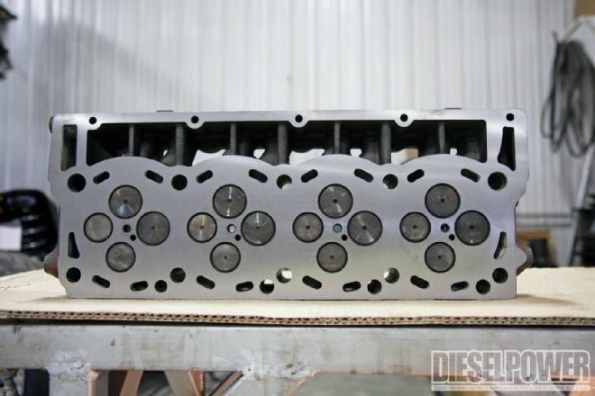
01. As with any engine build, quality machine work is top priority. Once back from the machine shop, we learned that only 0.003 inches of material had to be removed from one cylinder head, and 0.004 inches from the other, in order to resurface them. Most 6.4L heads typically require 0.005 to 0.006 inches worth of machining.
| 02.
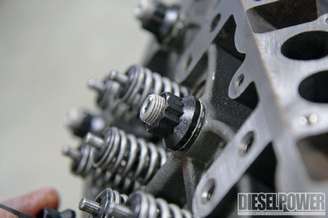
02. These Stage 2 valvesprings from Elite Diesel Engineering eliminate the possibility of valve float (due to high boost, drive pressure, rpm, or a combination of all three). They increase seat pressure to 145 pounds per inch (ppi), are polished for extended spring life, and come with chromoly retainers and keepers.
| 03.
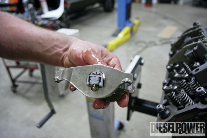
03. While valvesprings can be upgraded in-frame on a 6.4L, it’s much easier to handle the task with the heads off the block. Using a valvespring compressor (arrow), we removed the old springs and installed the Stage 2 Elite Diesel units in less than an hour. Once in, we made sure the keepers were seated by lightly tapping each valve with a hammer.
| 04.
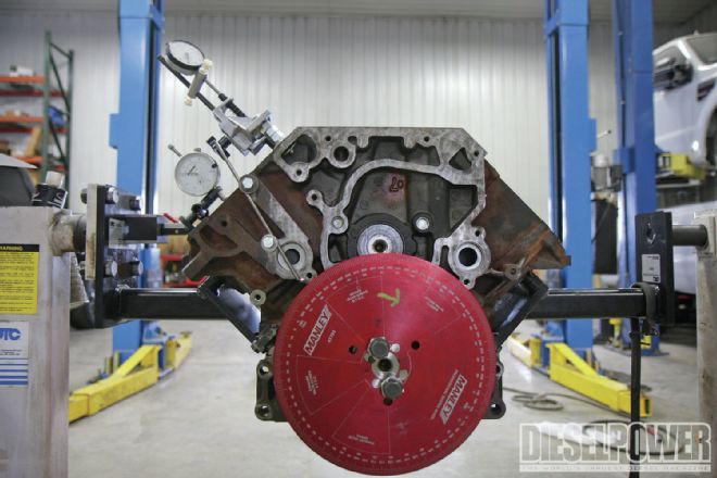
04. As an insurance item, we checked to make sure we had degree’d the Elite Diesel Stage 1X cam (installed in Part 2) correctly with the crankshaft, and that we were within Elite’s specs. Note, Elite ships its cam with the cam gear correctly timed, but it’s worth the peace of mind to find out whether your intake and exhaust valves will be opening at the appropriate interval before the engine ever fires up.
| 05.
05. In this photo you can see where the 6.4L block is notorious for cracking. Cracks occur along a casting line in the lifter valley, on the inside of the number 3 and 5 head bolt bore on either bank -- and right next to two water jackets. According to Swamp’s Diesel Performance, the block’s wall thickness in this area is less than 0.200 inches (0.174 inches to be exact). Once there are cracks, coolant makes its way into the lifter valley and begins contaminating the engine oil. Torquing 6.4L head studs higher than 200 ft-lb has been blamed for fracturing these weak areas of the block.
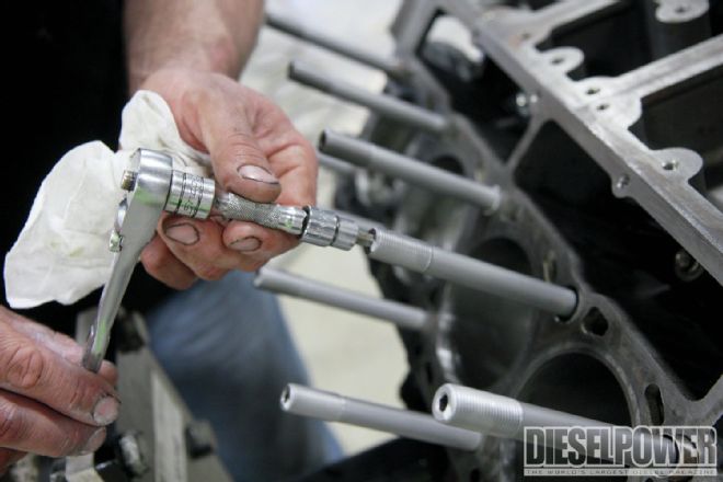
| 06.
06. To make sure the head bolt bores were clean and the threads were properly prepped for the head studs, we bottomed out a 16x1.75mm tap in each hole. Then, compressed air was used to rid each bore of any leftover debris.
| 07.
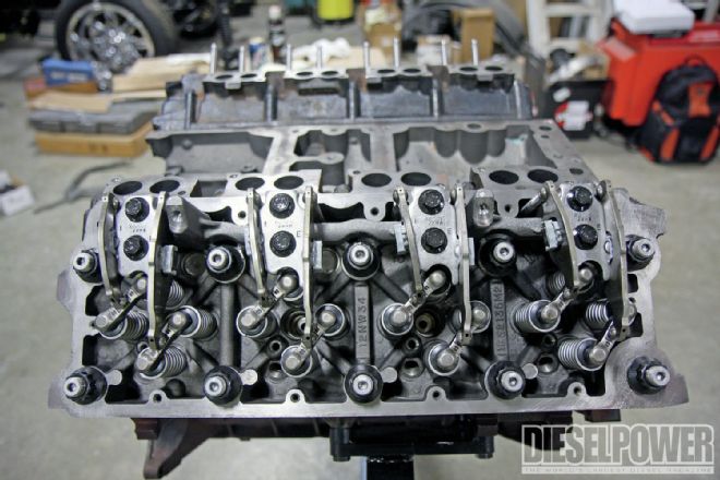
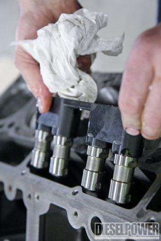
07. After we submersed the new, OE hydraulic lifters in clean, 15W-40 Shell Rotella motor oil, they were installed. Each set of four (Ford PN 8C3Z-6C329-B) came from Ford and included a guide. Once in place, the lifter guide hold-down bolts were coated with Loctite and torqued to spec.
| 08.
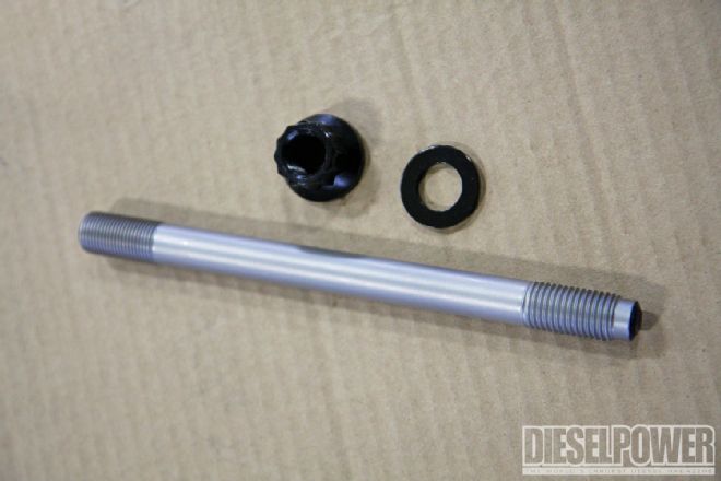
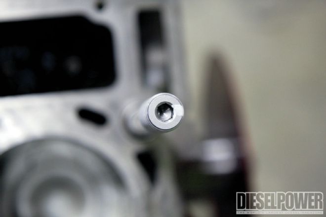
08. Also sourced from Elite Diesel Engineering was a set of A1 Technologies head studs, which will be tasked with clamping the heads to the block. Made from H-11 alloy steel, the 16mm (od) studs have a minimum rating of 240,000-psi tensile strength, and they come with high-strength washers and 12-point nuts.
| 09.
09. Prior to installing the head studs, we took several white rags to the block’s deck surface (and stopped wiping when a clean rag no longer picked up any debris, oil, or discoloration). Then the cylinder head alignment dowels were installed in the block, all head stud threads were coated in clean motor oil, and each was threaded into the block (handtight, until bottoming out). After that, each head stud was backed off a quarter of a turn.
| 10. To know for sure how far we’d backed off the head studs, we marked each fastener with a white dot. This way, we would be able to tell if the studs were spinning during the torqueing sequences and make sure we only loosened them a quarter of a turn.
10. To know for sure how far we’d backed off the head studs, we marked each fastener with a white dot. This way, we would be able to tell if the studs were spinning during the torqueing sequences and make sure we only loosened them a quarter of a turn.
| 11.
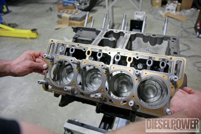
11. With the head studs bottomed out in the block and loosened a quarter of a turn, both factory head gaskets were installed. The four-layer gasket’s part number (International PN 1876484C1) supersedes previous head gaskets for the 6.4L Power Stroke.
| 12.
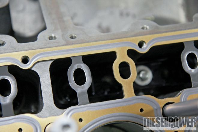
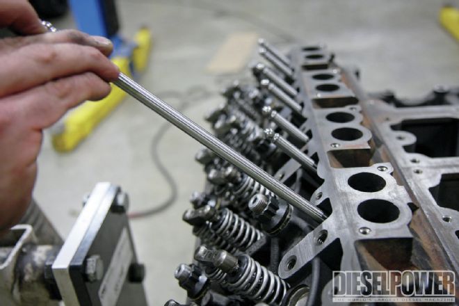
12. Because we planned to run larger diameter pushrods, the pushrod passageways in the head gaskets had to be enlarged to clear them (arrow). We simply used a dye grinder to make them bigger (doing so before the gaskets were installed, of course).
| 13.
13. Next, it was time to muscle the cast iron heads carefully onto the block. From there, the supplied A1 Technologies fastener lubricant was applied to the head stud threads, washers, and nuts.
| 14.
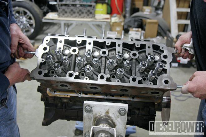
14. In order to keep the head studs from turning, an Allen socket was used to hold them in place while the nuts were handtightened.
| 15.
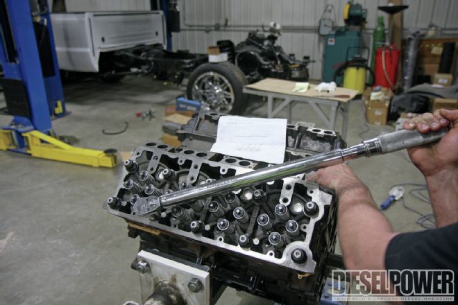
15. Per Elite Diesel’s instructions, the head studs were torqued in two separate phases (to obtain the proper fastener stretch). First, the studs were torqued, center out, to 90 ft-lb. Then the nuts were loosened and the process was repeated two more times. After the third loosening sequence, the nuts were removed and recoated in the A1 Technologies fastener lubricant. The second phase included the final torque sequences, which were 50 ft-lb, 110 ft-lb, 150 ft-lb, and 195 ft-lb.
| 16.
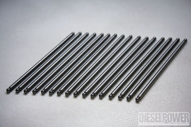
16. To rule out pushrod flex at high rpm and take full advantage of the Stage 1X cam’s added lift, we opted to run these Stage 2 units from Elite Diesel. They’re made from 4130 chromoly, have a 0.145-inch wall thickness, and are a direct complement for the company’s Stage 2 valvesprings. As mentioned earlier, these pushrods have a larger od than the stockers (3⁄8 inch vs. 5⁄16 inch), hence the requirement to enlarge the pushrod passageways in the head gaskets.
| 17.
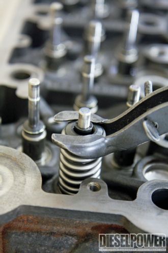
17. Once the Stage 2 pushrods were in, the ends were hit with engine assembly lubricant. The rocker arm bases were installed after that.
| 18.
18. Addressing another weak link in the 6.4L’s valvetrain, we had the factory rocker arms cryogenically treated by 300 Below in Decatur, Illinois. During high-rpm scenarios in which valve float occurs, they can break. According to 300 Below, cryo treatment makes them 30 percent stronger. Between the stiffer valvesprings, stronger pushrods, and cryo’d rocker arms, we think this engine’s valvetrain is more than capable of surviving big horsepower.
| 19.
19. With the rocker arms installed and their bolts torqued to 45 ft-lb, the only thing left to do was perform the same work on the other head, then add glow plugs, injectors, the fuel rails and lines, and the valve covers. We’ll tackle that next time, when we install brand-new injectors with 200hp nozzles, dual K16 high-pressure pumps, and a serious low-pressure fuel supply system.