Last month I showed you the basic floorpan I cut from a sheet of 18-gauge to use as the starting point for the Homebuilt Hot Rod's floor. This time around I'll show you how I handled its installation and the fabrication of the toe-board section. As you'll recall, I started the process by making patterns out of cardboard and then transferred the pattern onto a sheet of 18-gauge. I began by taking measurements fore and aft, both width-wise and length-wise, and then transferred the dimensions to some cardboard I used for a template. I then traced the template onto the sheetmetal and trimmed it to fit the cab as one piece. Well, that worked fine for starters, but then I had to complete the process-which I'll do here. So check out how I went about finishing up the Homebuilt's floorpan assembly. Hopefully it will at least give you an idea of how to tackle a floor of your own when the time comes. Just keep in mind that though my techniques end up working, I don't always go about these chores the way a professional may. Heck, if I were a professional, I'd be building cars on TV, not sittin' behind a PC.
It's getting closer to the road-granted not as quickly as I'd like, but I'm gaining on it.
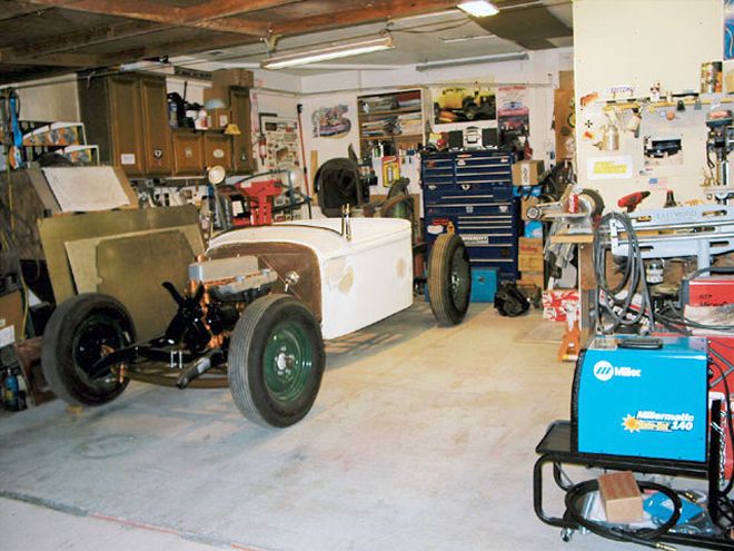
Here's where I left off last month. The one-piece pan was in place and waiting for the toe-board assembly and mounting points.
The first thing I did after cutting the basic pan was measure and cut a shifter hole on the pan. Of course, I measured incorrectly the first time, but I recovered from my stupid mistake by cutting a trim plate to correct/hide my error (don't tell anybody).
It was at this point that I stepped back and considered my next step. Did I want to make the complete floor permanent, or should I make it removable? I thought I'd make the floorpan fully removable, since the brake and clutch masters are located under the floor and I knew I'd want to get under the floor in the future. To accomplish this I decided to split the main pan into two sections-a right and a left.
I cut the pan from front to back, just to the right of the shifter opening; I then realized I'd have to reinforce the new seam in some manner since there were no floor supports under that section.
As usual, I began the task by making yet another cardboard template. I started at the foot pedal area by trimming the cardboard to fit the left side of the cowl and to bridge the gap between the main pan and the firewall. With the template trimmed to shape, I then marked it to match the pedal cutouts in the pan so I'd know where to trim the finished section.
I decided the easiest way to accomplish this would be to punch a string of holes inward of the inner edge of the right-hand section so I could attach a supporting step along the seam.
Here's a shot of the right-hand section in place in the cab. You can see the flange running front-to-back along the inner edge. (If you look closely at the top center of the picture, you'll see my shifter mounted to the trans crossmember ... but that's another story.)
I cut another 3-inch strip of 18-gauge sheet and rosette-welded it (using my new Miller 140 with AutoSet MIG welder, by the way) to the bottom of the right section to act as a flange on which the edge of the left pan would sit.
The next step was to mark the location and drill a string of mounting holes in both the flange of the right-hand floor section and the right edge of the left section of floorpan; this way both sections could be attached to each other once they were in place, basically making it one piece again.
I then took some 3/16 bolts and nuts and ran them through the holes in the flange.
With that done, I reinstalled both sections of the floorpan and went back to work fashioning the toe-board sections.
Back at the toe-board chore, I transferred the template to the sheetmetal and trimmed it up.
I welded the nuts to the bottom of the flange so I wouldn't have to worry about trying to hold the nuts from under the truck while I was trying to tighten them from the top (one of the few moments when I was actually thinking ahead).
I used my Eastwood brake to bend flanges at the top and bottom so it would fit against both the floor and the firewall.
Fast forwarding a bit, I then cut a toe-board section for the balance of the floor that would also act as the small trans tunnel I'd need as well.
I made some filler pieces at the union of the two sections to join them, so the toe-board ended up as one piece. I also opted to bolt the toe-board into place so it, too, is removable. And there you have it-not the prettiest fabrication job, and perhaps not the way you might want it in yours, but you get the idea anyway. See ya next time.
Eastwood Company800-343-9353www.eastwoodco.com
Miller Electric Manufacturing Co.920-734-9821www.millerwelds.com