 Taking time to align your car is worth every minute and ounce of effort. Knowing where your car is pointed and eliminating any errors can save countless hours of frustration and a lot of wasted expense chasing an errant setup. Many handling problems can be traced directly to misalignment of the suspension.
Of all the setup parameters, including moment center location, alignment ranks at the very top of the list. Why? Because when your alignment is off, no other setup parameter changes will compensate for it. The alignment package has a tremendous influence on the way a race car handles.
For example, I recently talked with a Florida asphalt Modified team that I worked with some years ago. This is a winning team that cannot get the car to work the way past cars have worked. I reviewed the moment center design and the setup: The car should have been a rocket ship.
The last question I asked, last only because I thought they would know better, was if they had any Ackermann in the car's steering system. The answer was shocking. On the turn plates it showed about 2 degrees in the amount the wheel is usually turned to get through the turns at their local track. That is a huge amount of Ackermann and added toe-out, as we will explain.
Another example involves an ASA car at Lakeland that absolutely could not get into the corner because it was so loose. The driver/crew chief swore that the car was aligned. The problem was a misaligned rear end, with the right-rear wheel back 3/4 inch too far.
Alignment is a first priority in setting up any race car. It really doesn't take long, and the benefits are as great, or greater, than any other setup task you will perform. If you have not checked the alignment of your car, do it now. Follow along as we explain race car alignment and why it is necessary.
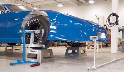
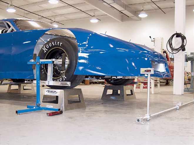
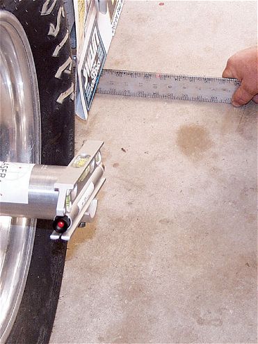
 In the past, it was common to string a car by making marks on the floor. This is a good method for checking rear-end square and can be used to line up the right-side tires. It takes longer than the raised string method, but can be more accurate due to the process of dropping points to the floor with a plumb bob and then making direct measurements to the rear end.
The Elements Of Proper Alignment
A. Toe Settings Proper toe settings at the front and the rear are very important. A set of tires that is not toed correctly will create a lot of drag, much like applying the brakes, and sometimes more efficiently than the actual brakes. The standard of the circle track industry is to toe the front out 11/416 to 11/48 inch. The rear wheels are to be straight-ahead and parallel to each other, having no toe at all.
Some teams desire some amount of toe-out or toe-in at the rear, whether it is desirable or not. Some formula cars are designed to work best with a small amount of toe-in at the rear. These cars are mostly rear double A-arm suspension cars, not straight-axle cars.
One theory claims that the tire contact patch deflection dictates the toeing of one or more of the rear wheels to compensate for that deflection. But it is hard to justify and can probably be best defined as a crutch used to help solve some other setup miscue.
B. Front-to-Rear Tracking The tire contact patches must track straight-ahead from front to rear, and in most cases, we need to line up the right-side tire contact patches. Our final alignment will show the right-side patches are in line with one another, along with the rear end being perpendicular to that line.
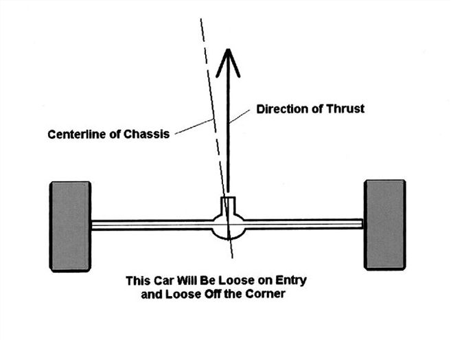 In this example, the rear end is pointed to the right of the centerline of the car. This will help free up a tight car, but will produce a severe loose condition under throttle application. The loss of bite off the corner will hurt the lap times more so than what might be gained from freeing the car up.
C. Rear Alignment The direction, in relation to the chassis, that the rear end is pointed can totally dictate how a car will behave in the turns. For example, on turn entry, if the rear end is pointed to the right of the chassis centerline, no amount of setup tuning will prevent the car from being loose. That looseness will stay with the car throughout the turns, especially ruining the turn exit. If the rear end is pointed to the left of the centerline of the chassis, the car will be tight through the middle and off the corner.
There should never be any reason to misalign the rear end. It should always be perpendicular to the centerline of the chassis and to the right-side tire contact patches, which are themselves inline.
D. Ackermann Adjusted The last alignment priority, and one of the most important, is making sure you have very little Ackermann, which is the creation of additional front toe as the wheels are turned. On most 1/4- to 1/2-mile racetracks, we need very little Ackermann to make sure the wheels are tracking inline with the radius of the turn for each wheel.
Calculations show that for circle tracks with fairly large radii (much more than was used to design our passenger cars to turn the corner at the stop sign), a very small amount of added toe is needed to properly align the front wheels to their individual radii.
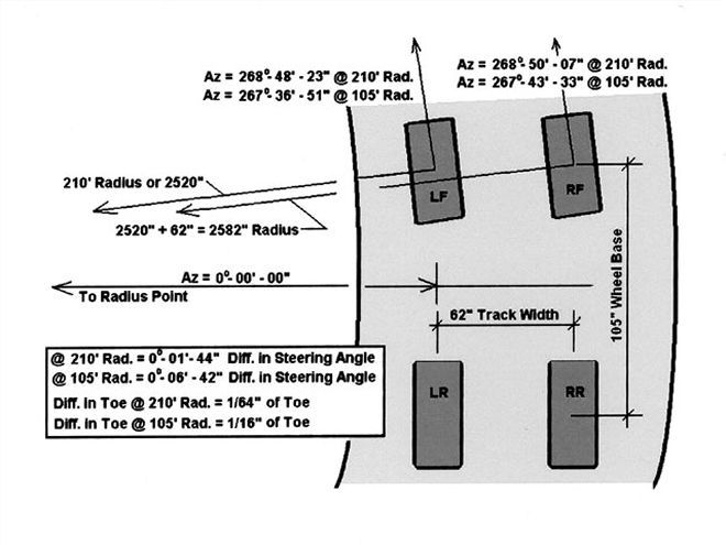 To discover exactly how much Ackermann is required in a typical stock car, we used a very accurate coordinate geometry software program to calculate the steering angle difference between the two front tires needed for a 11/44 and 1/2 mile racetrack. We then translated the angles into decimals of inches of toe.We can see that for a 1/2-mile track we would need only about 1/64 inch (or 0.03 degree) of additional toe, so the tire would follow the needed track due to the difference in radius between the front wheels.For a "tight" 1/4-mile track, we need slightly more toe again, or about 11/416 inch (or 0.11 degree) of additional toe. These numbers represent fractions of degrees of Ackermann, not whole degrees. Remember, each degree of Ackermann is a full 1/2 inch of toe.
The true amount of Ackermann needed for a 1/2-mile racetrack is 1/64 inch of added toe, or about 0.015 inch. We usually set 1/8 inch of static toe, or 0.125 inch, so there is plenty of existing toe-out to compensate for the Ackermann needed.
On a tighter 1/4-mile track, we will need a whopping 1/16 inch, or 0.063 inch, of added toe in order for the wheels to track correctly. This is still well within the initial 0.125 inch of static toe-out we set in our cars.
For your information, 1 degree of Ackermann is equal to 1/2 inch of additional toe-out. Some teams have run 2 degrees or more of Ackermann, expecting the car to turn better. Would you set your car up with 1 inch of static toe-out? I seriously doubt it. But this issue of Ackermann keeps rearing its ugly head, even after we have explained it several times in the past.
Steps to Take in Aligning the Car
There used to be only one reliable way to align a race car and that was by using a string and either measuring to the tires at hub height or at the floor by measuring from right triangles that were created on the floor. That is still a viable way to do it and necessary for the lower budget race teams.
A quicker and more accurate way to align the car in all areas is to use a laser system. The key to maintaining accuracy in a laser system is to check the tool to make sure the beam is truly tracking at right angles to the mounting device. The units we have used in the past are the True Laser Track and the Real Square(tm) Laser Wheel Alignment System. Both of these systems allow for checking the accuracy of the laser beams. This must be done each and every time we use the tool to check alignment.
The laser systems attach to the wheel hubs (Wide-5 or 5-on-5 hubs) and are pointed at targets or measuring scales. For the "analog" method, we used a nylon string from the local hardware store. We will go through the process using both methods so you can see how to perform each step.
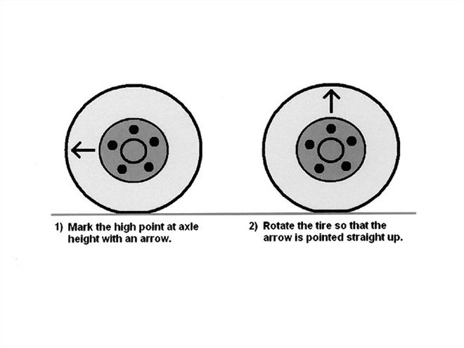
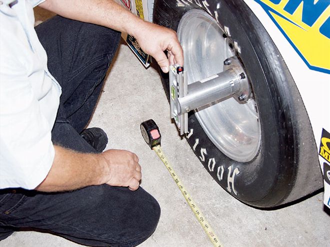
Step 1: Wheel Runout Check Check both the front wheels and the rear wheels for runout. This means that as the wheel rotates, the outer edge of the tire wobbles slightly. We must compensate for this slight distortion by finding the extreme high spot at a point equal in height to the hub height. We can simply use a jackstand to hold the tape steady and rotate the tire, noting the distance from the stand. Once we locate the high point, we mark it with an arrow and then rotate the tire (be it front or rear) so the arrow is at the top, pointing straight up.
Now, check the toe at the rear end. Use toe plates or toe bars for the analog method and the laser systems for a more accurate assessment. Even small amounts of toe-in or toe-out are not acceptable. Each person must hold the plates steady so that the measurements are consistent. Measure several times to ensure accuracy.
When using the laser systems, attach the laser to the hubs, remembering to thoroughly clean the surface of the hub. Make sure there are no protruding threads from the bolt holes. It is recommended that you go over the hub surface with a flat file to eliminate any bulges or protruding edges of metal that would cause the laser to not be aligned properly.
Follow the manufacturer's recommendations for setting up the laser systems. Remember that the accuracy of the measurements is directly related to how closely you follow the directions and how carefully you read the system. There is a logical progression to alignment, and each company has put a lot of thought into the methods. The results, if properly applied, will be the same.
 The True Laser Track System sends a single laser beam to the ground and to targets placed at the front and rear of the car. The system can check wheelbase, alignment, Ackermann, toe, and more.
Step 2: System-to-Frame Setup Once the rear wheels have been toed straight-ahead, square the laser system to the frame. Most car builders will align at least one framerail parallel to the intended centerline of the chassis. It may be located on the right side or as the weight box on the left side, next to the driver. You can also align the laser system to the centers between the front and rear clip rails closest to the main framerails.
This setup can also be done using strings. We will set up a "box" with strings on each side and at the front and rear. We use plumb bobs to make marks on the floor off the outside of the framerails or the front and rear clip rails. For perimeter cars, or cars with no offset in the chassis, we can split the measurement between the clip rails to find the centerline of the chassis.
For offset chassis, we could use a straight rail or we could split the clip rails. Measuring between the marks, we can split the distance in half and place a mark at the halfway point, or at the centerline of the car.
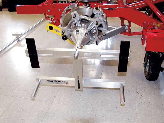 The Real Square(tm) Alignment System uses scaled bars attached to a fixture that bolts directly to the hub. After the lasers are set up and aligned with the chassis, the wheel alignment and toe can be read on the scaled bars. Ackermann can also be checked with this system, along with other parameters.
Step 3: Center the Steering Box Center the front steering rack by turning the steering wheel lock-to-lock and back half the number of turns from full lock in either direction. Once mid-rack (or mid-box with drag link steering) is found, lock the steering shaft with two vise-grip pliers.
We want to make sure the steering is centered and the wheels are pointed straight-ahead. Once the steering box has been set to center, adjust each tie rod so that the right and left wheels are pointing straight-ahead. With the laser systems, this is done quickly and accurately.
With the string method, run a string down each side of the car at hub height and parallel to the centerline you have established. Then, simply measure to the sidewalls of each front tire with the tape measure, and make both front and rear sidewall measurements of each front tire equal by adjusting the tie-rod length. We can set our race toe after we have aligned the car.
Step 4: Right-Side Tire Contact Patch Alignment Once the front wheels have been adjusted to point straight-ahead and parallel to the centerline, we need to align the right-side tire contact patches. We do this by using our laser systems as described in their user manuals.
Adjust the Panhard or J-bar length so that the right-side tire contact patches are in line, or if your desire is to offset these, set the desired amount. This means that we either have both right-side tires lined up or at least know what our offset is.
When using the string method, we need to compensate for the camber of the wheels, which moves the tire contact patches out. At the hub height, if we line up the tire sidewall, the RF tire contact patch will be outside that line due to the negative camber present in the RF wheel. The rear wheel may also have camber set into it. Look at the chart to estimate how much to compensate for the cambers. Subtract the compensation amount from the offset read at the wheels to find how far from the string the wheels need to be in order to line up the right-side tire contact patches.
 The offset to the frame measurement can be taken by using a laser or a string. The string is a must for a low-budget team, but the laser systems are much more accurate and do more alignment tasks in less time.
As we adjust the rear end side to side, there is a possibility that the rear-end alignment will change as the rear end moves laterally. That is why we do the right-side alignment first. We will now need to check to make sure the rear end is perpendicular to the chassis centerline and if not, adjust it.
Step 5: Rear-end Alignment Once the right-side tire contact patch alignment has been completed, we can then square the rear end. The rear end should always be set perpendicular to the centerline of the car as well as to the right-side tire contact patches.
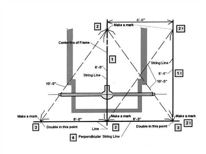
We do this by creating a line that is perpendicular to the centerline we have already established. Using a simple 3-4-5 right triangle with the lengths doubled, we can measure off the centerline to establish our line to measure to the rear end.
Step 6: Setting Front Toe It's time to set the static toe at the front wheels. We can use toe plates to do this. Remember to be careful and accurate, and measure several times to be sure of the numbers. Adjust the left-side tie rod to set your toe. Leave the right side alone.
Roll the car and recheck the toe setting. Remember that for toe-out, the front measurement will always be more than the rear measurement. If you are using a string or laser, as opposed to toe plates, to check your toe-out, the opposite is true. The front measurement from the laser/string would be less than the rear measurement. I know a crew chief who got this backward too many times.
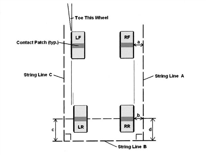
 This is what we should end up with after aligning the rear to the right-side tire contact patches. Measurements "a" and "b" should be equal, as well as dimensions "c" and "d."Once the rear end has been toed straight-ahead, aligned perpendicular to the chassis centerline, and the right-side tire contract patches are lined up, we will deal with the front toe and Ackermann issues.
Step 7: Ackermann Measurement It is now time to measure for the amount of Ackermann in the steering system. This is best done accurately with the laser system. However, the analog method would use strings and can also tell us whether we have unwanted Ackermann or not.
If using a laser system, follow the manufacturer's suggestions and recommendations for measuring for Ackermann. If you do not have a laser system, you can use strings. Here is how you do it.
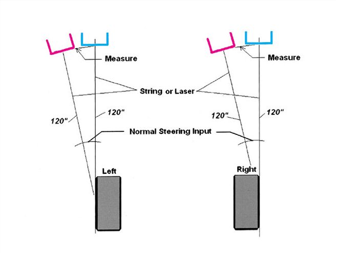
Start by pointing the front wheels straight-ahead. Pull a string along the outside of the tires at the tire bulge at about the spindle pin height. Go 10 feet in front of the car and make a mark on the floor, with the string aligned with the sidewall (I use a piece of wide masking tape and a permanent marker). Do this for each front tire.
Then, turn the steering wheel about the same amount it is turned on the track when you're going through the turns. Again, string the front tires and make marks at 10 feet out in front of the car. The distance between the two marks for each wheel should be the same for the left-front wheel and the right-front wheel if there is no Ackermann present. If those distances are different, there is some amount of Ackermann or reverse Ackermann present.
 The tire contact patch is offset from the center of the wheel at hub height when we add camber to a wheel. The chart shows how far offset the contact patch center is related to the wheel center at hub height.
A greater measurement on the left indicates Ackermann (gain in toe-out), and a greater measurement on the right indicates reverse Ackermann (loss of toe-out). A 1-inch difference equals about 1/4 inch of Ackermann, or added/loss of toe. So, if you can get your differences to around 1/4 inch (where the left side is more), you should be good to go. A recent car we checked had a 3-inch difference, or almost 3/4 inch of added toe in the turns. That's way too much.
Conclusion This whole process of aligning your car should take only about an hour or two if there are several team members helping. That is very little effort expended to make sure your car will track correctly and that misalignment will not interfere with your car's performance.
Repeat this entire process often, especially after kissing the wall or being involved in a crash. Once you are convinced that your car is aligned, you can then concentrate on the other important aspects of your chassis setup.
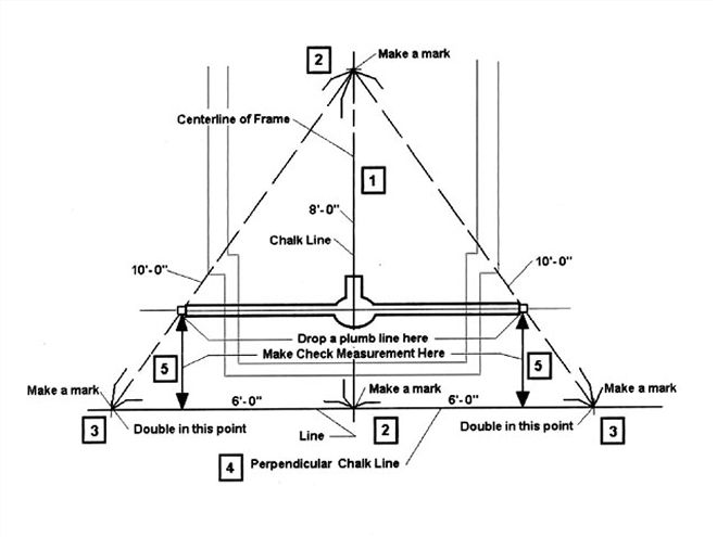
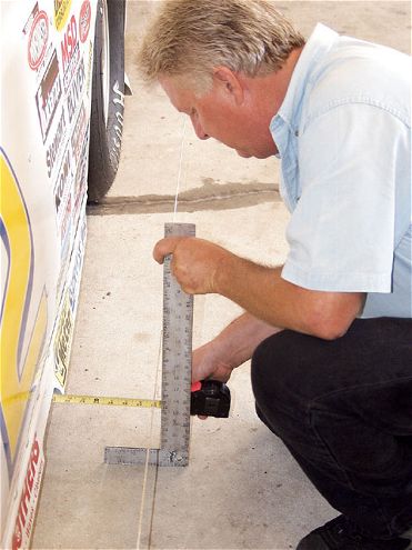
Here, we see the layout for the process of setting up to square the rear end. Note that the lines formed by the intersecting marks are right triangles. Take your time and measure very accurately. Remeasure if you feel that everything is not right once you pull the rear string line across the outer points of the triangles.
Laser systems are the best tools to use to check for the presence of Ackermann. If you do not have one of those, you can use strings to project the alignment of each wheel out in front of the car.