OK, so you checked off the option box for the 6L80E automatic when ordering up your new fifth-gen. Unlike your buddies in the local Camaro club that insist on shifting manually, after an evening of navigating the urban jungle on cruise night at least your left leg still works. You can even run more consistent e.t.’s at the dragstrip, too. Indeed, these are great perks to rub in the face of your TR-6060-equipped counterparts, but it doesn’t change the fact that the L99 packs 26 fewer horsepower (400 vs. 426) than the LS3. Sure, that’s hardly a big difference, but it gives the manual boys bragging rights, nonetheless. While both 6.2L small-blocks are essentially identical, the bulk of the hp gap is attributable to the L99’s active fuel management (AFM) and variable valve timing (VVT) systems, which shut down half the cylinders under light loads and continually alter camshaft phasing to improve fuel mileage. While the VVT tables can be reprogrammed to enhance performance, GM utilizes it to boost fuel mileage instead. Moreover, both AFM and VVT require GM to dial back on the cam lobe profiles, and in the case of the L99, the specs measure out at an incredibly miniscule 195/201 degrees of duration at 0.050 with just 0.500/0.492-inch valve lift. As with all Gen IV small-blocks, cam swaps are worth some serious hp in the L99, but there are some unique factors that must be taken into account. Fortunately, none of these challenges is difficult to transcend.
Rumors and myths run rampant regarding the intricacies of a VVT cam swap, but for owners of L99 Camaros there are three options. The most obvious choice is upgrading to a cam that’s compatible with both AFM and VVT. This involves limiting valve lift to roughly 0.540 inch and keeping the duration short enough to where extreme valvespring pressure isn’t necessary. That’s because AFM relies on application-specific lifters that can’t handle aggressive lobe lift, and excessive valvespring pressure can compromise the ability of the VVT system’s hydraulically actuated phaser to control camshaft timing. At the extreme opposite end of the spectrum, a second option is eliminating both the AFM and VVT systems with standard LS-style lifters and a non-VVT single-bolt camshaft and timing set, which allows running as much lift and duration as the cylinder heads and short-block can support. Unless plans call for turning 7,000-plus rpm and pushing the limits of the stock bottom-end, however, perhaps the ideal compromise for many street/strip machines is eliminating AFM while retaining VVT. After all, in the hands of a skilled tuner, VVT is a great power-boosting tool. That’s exactly what we witnessed as the crew at Advanced Racing Dynamics in Houston installed an off-the-shelf COMP Cams 222/236-at-0.050 hydraulic roller grind into a mostly stock L99 Camaro. The result was a solid 41hp gain at the rear wheels.
According to ARD’s Owen Priest, the decision on whether or not to keep AFM or VVT hinges upon each particular application. “We’ve built supercharged cars that make 700 rear-wheel hp that still have AFM and VVT. That’s because blower motors don’t need a lot of valve lift,” he explains. “However, in naturally aspirated cars we typically get rid of the AFM system because the lifters are prone to failure at anything beyond 0.540- to 0.550-inch lift. When AFM is enabled, it creates an exhaust drone, which a lot of people don’t like. As for the factory VVT system, we’ve pushed the lift as high as 0.600 inch, but after that it’s best to go with an LS3 valvetrain conversion.”
Although ARD knocked out the cam install in one day, the average DIYer should plan on setting aside a full weekend to finish the job. Even so, it’s a small price to pay for the huge bump in power a simple cam swap will deliver.
Parts List Item PN Price COMP Cams camshaft 156-403-13 $435 COMP Cams phaser limiter 5456 $60 Manley valvesprings 221438-16 $347 Manley pushrods 25735-16 $147 Fel-Pro head bolts (x2) ES72220 $74 GM LS3 lifter valley cover 12599296 $130 GM LS3 lifter buckets (x4) 12595365 $36 GM lifters 17122490 $53 GM head gaskets (x2) 12610046 $86 GM balancer bolt 12557840 $5 Total: $1,373
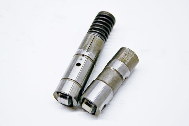
01. The heart of the L99’s AFM system are collapsible lifters (left) that are used on cylinders 1, 4, 6, and 7. Compared to a standard lifter (right), the AFM units feature a two-piece body in which the inner portion of the lifter slides inside the outer sleeve. When AFM is activated, hydraulic pressure is fed through an orifice in the lifter body that causes its retainer pin to unlock. Valvespring pressure then forces the AFM lifter to collapse, allowing the outer sleeve of the lifter body to slide around the inner portion of the body instead of transferring reciprocating motion to the pushrod. Once AFM mode is deactivated, an internal spring on the bottom of the AFM lifter’s inner sleeve pushes it back upward, and the retaining pin locks back into place.
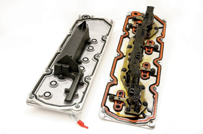
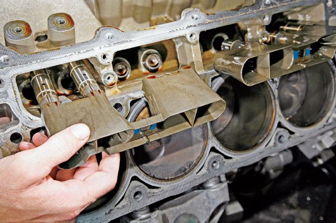
02. The brains of AFM operation is a lifter oil manifold assembly (right) positioned beneath the lifter valley cover. The LOMA taps into the oil system and feeds hydraulic pressure to the lifters in cylinders 1, 4, 6, and 7. To make room for the LOMA assembly, GM relocated the knock sensors from the lifter valley to the sides of the block when the Gen IV was introduced. Deleting the AFM system requires replacing the L99 valley cover with an LS3 unit.
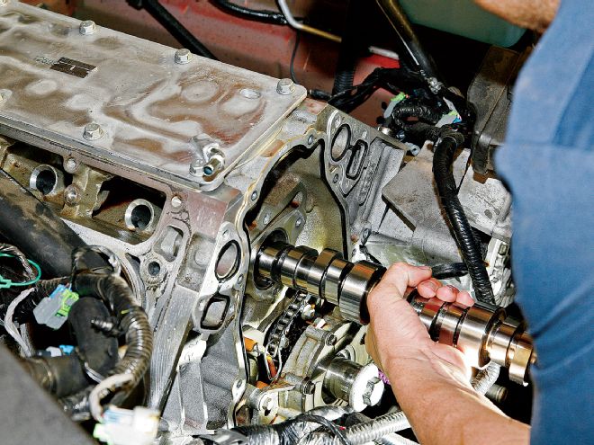
03. Eliminating AFM allows running a much more substantial camshaft. The COMP 222/236-at-0.050 hydraulic roller cam installed in our test subject provides a big bump in duration over stock, along with 0.566/0.578-inch lift and a 114-degree lobe separation angle. As with all VVT cams, oil is routed from the Number 2 cam journal, through the center of the cam core, and then to the cam bolt. Although you can get away with merely swapping out the AFM lifters on cylinders 1, 4, 6, and 7 with standard LS units, ARD elected to replace all 16 of them. The AFM lifter buckets must also be replaced with LS3 buckets.
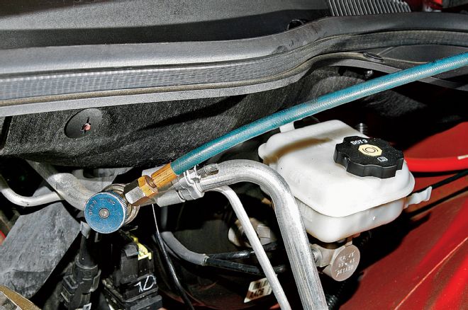
04. In addition to draining the oil and coolant, ARD prefers to start by discharging the A/C refrigerant (via a refrigerant recycling machine) in preparation for removing the condenser. Although it’s possible to swing the condenser upward, thereby eliminating the need to discharge the system, this method runs the risk of breaking the hard lines.
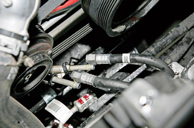
05. At the front side of the engine, the A/C, power steering, and transmission cooler lines need to be disconnected before removing the radiator and condenser. While there is a disconnect tool that’s supposed to make the job easier, ARD says it’s quicker to hold the retaining nuts with a 15mm wrench while removing the clips with a flat screwdriver.
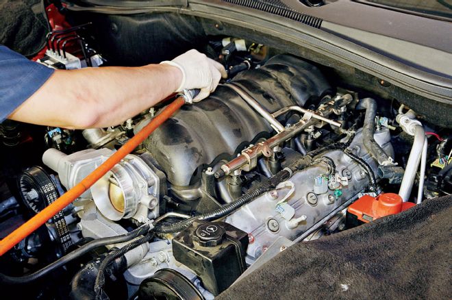
06. After removing the coil packs, engine shroud, and air-intake assembly, next on the list is the intake manifold. Before unbolting it from the heads, a bevy of electrical connectors need to be unhooked, including the injectors, MAF sensor, throttle body, MAP sensor, and EVAP solenoid. The fuel line and brake booster hose must be disconnected as well. With the 10mm bolts removed, ARD lifted the intake manifold off of the heads.
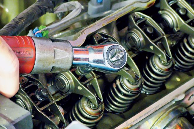
07. Before the cylinder heads could be unbolted, ARD removed the valve covers, rocker arms, rocker stands, and pushrods. The header bolts were removed as well.
08. Accessing the timing cover requires first removing the water pump. Before doing so, ARD removed the serpentine belt along with the two heater hoses from the passenger side of the water pump. The upper and lower radiator hoses were disconnected as well.

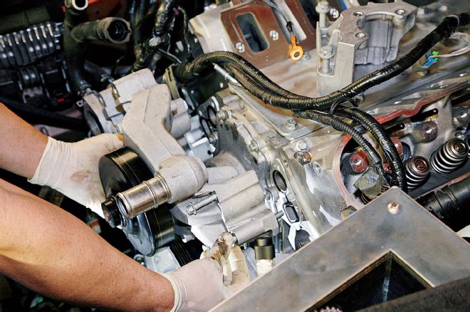
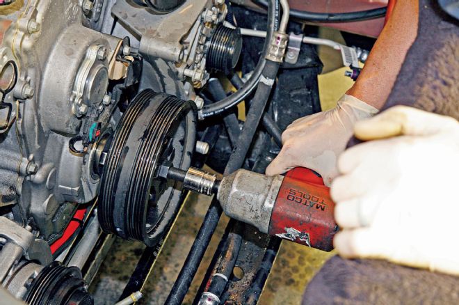
09. To finally remove the heads, the headers and power steering pump (driver side) must be unbolted. Reaching the bolts on the pump requires clocking the power steering pulley in just the right spot in order to fit a socket and extension through it.
10. With the heads out of the way, ARD unbolted the lifter buckets from the block and pulled them out along with the lifters. A telescoping magnet may be necessary to coax some of the lifters out of their bores. Note how the buckets for the AFM lifters on cylinder 1 (left) feature internal ribs that help center the taller lifter assemblies.
11. Even before the stock cam was removed from the block, ARD swapped out the L99 lifter valley cover for the new LS3 unit. Minimizing the time the lifter valley is exposed to the elements reduces the likelihood of contaminants entering the oil system.
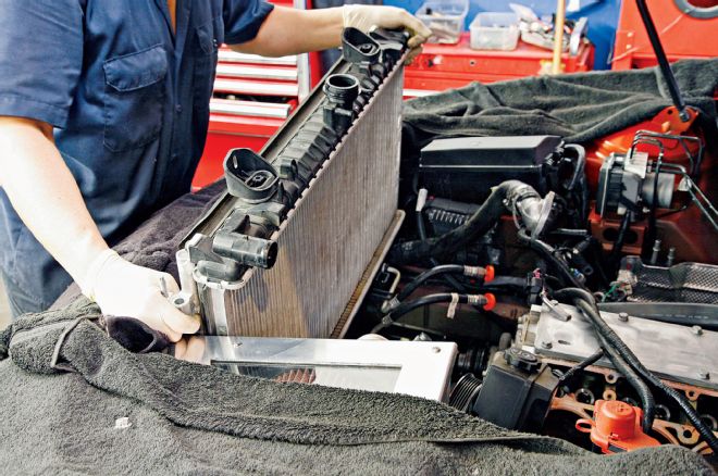
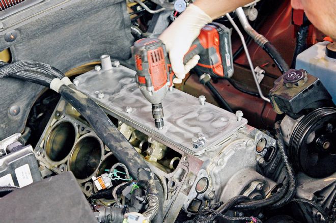
12. Removing the harmonic balancer bolt is a job best left for an impact wrench. To make room, ARD pulled out the radiator and A/C condenser as a single unit after removing the cooling fans. The fans attach to the top of the radiator with two bolts, and the radiator attaches to the core support with two bolts as well.
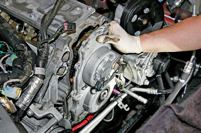
13. In order to provide adequate clearance, the alternator bracket must be detached from the driver side of the block before unbolting the timing cover. VVT timing covers are easily distinguishable by their big upper hump. This houses an electric solenoid assembly that interfaces with the camshaft position sensor and engine management system to precisely alter camshaft phasing through pulse-width modulation.
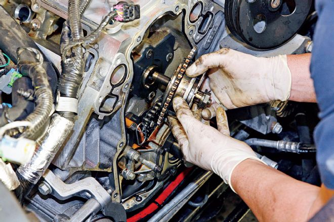
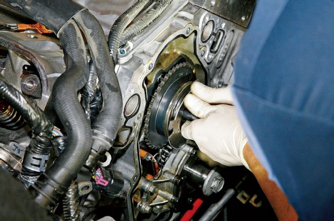
14. The cam phaser assembly is built into the timing gear and attaches to the cam with a single bolt. Since the timing chain and crank gear will not be replaced, the oil pump doesn’t need to be removed. During normal operation, an electric solenoid mounted behind the timing cover pushes on the front of the cam bolt, which doubles as an oil control valve. This controls the flow of oil into the phaser assembly, thereby manipulating valve timing.
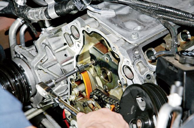
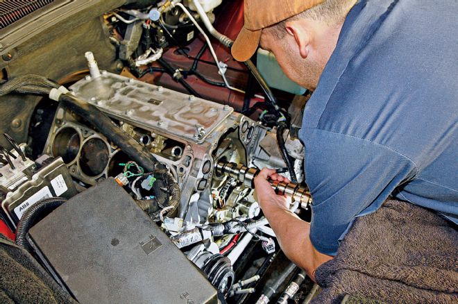
15. Four Torx bolts hold the cam retainer plate to the block. After removing them, the cam can be pulled out. Getting a firm grip on the cam is extremely important, since accidently nicking a cam bearing can seriously impede oil flow and pressure.
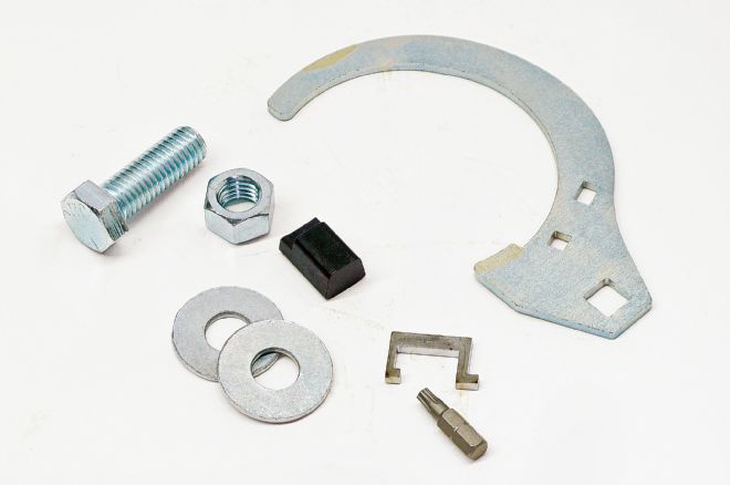
16. The factory VVT arrangement allows for a jaw-dropping 52 degrees of movement. While this is fine for the tiny duration stock camshaft, it introduces the potential for piston-to-valve interference with longer-duration aftermarket grinds. COMP has solved this problem with its phaser limiter kit, which limits cam movement to 22 degrees.
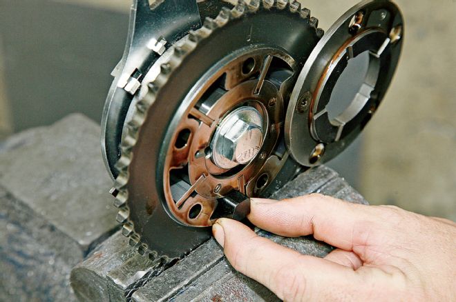
17. The L99’s phaser assembly is essentially a simple rotor-within-a-stator design. Oil is diverted outwards from the cam bolt to the space between the rotor vanes and the stator to control cam phasing. The actual phaser limiter is a small piece of metal that wedges between any one of the rotor vanes and stator. The other pieces of the kit simply allow for disassembling the phaser and help hold it in place. Removing four of the five Torx bolts allows swinging the phaser cover out of the way without completely detaching it.
18. Gently rotating the new camshaft while inserting it into the block can prevent the lobes from getting hung up on the cam bores. As the cam slides farther into the block, it’s not a bad idea to thread a long bolt into the cam snout to increase leverage, which will assist in holding it steady.
19. After re-attaching the cam retaining plate, it’s time to bolt the phaser assembly and timing chain back up. Before doing so, ARD lined up the arrow engraved into the cam gear with a dot engraved on the crank gear. This properly positions the camshaft in relation to the crankshaft.
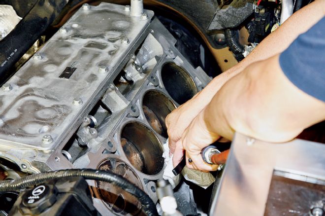
20. To prep the block for the re-installation of the heads, ARD cleaned the deck surfaces with a Scotch-Brite pad. Likewise, coolant was blown out of the bolt holes with compressed air to ensure accurate torque readings.
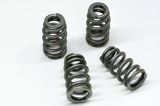
21. To handle the additional lift of the COMP camshaft, ARD installed new Manley beehive valvesprings onto the heads. They have 150 pounds of installed pressure and 375 pounds of pressure over the nose.
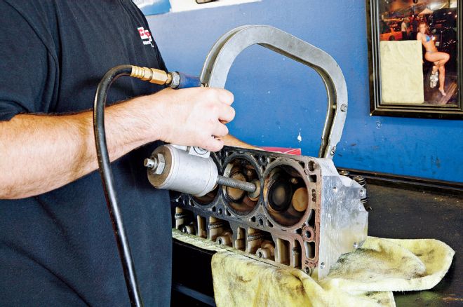
22. Using a pneumatic valvespring compressor, ARD made quick work of the spring swap. The process is very straightforward and involves compressing the spring, removing the valve locks and retainers, and then the spring itself. ARD verified the installed height on the first couple of springs, and since they checked out just fine, the rest were a drop-in-and-go affair. Afterward, the deck surfaces were cleaned, and the heads were power-washed.
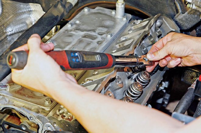
23. The factory head bolts are torque-to-yield units that are not reusable. After laying down a new set of GM head gaskets, ARD used a fresh set of stock replacement head bolts, which call for a very specific three-stage tightening process. According to the GM manual the bolts are first torqued to 22 ft-lb. The bolts are rotated another 90 degrees in the second stage using a torque angle meter, followed by another 70 in the third stage. Rocker arms are much simpler, since the valve lash isn’t adjustable. Simply torque down to 22 ft-lb and call it good.
24. With a few exceptions, re-assembling the balance of the engine and accessories is the exact opposite of the removal process. Of particular note is the balancer. It’s imperative to get the installation process correct to avoid having the bolt back out. Since the stock LS7 bolt is longer than that of a standard LS engine, ARD uses it to start the process of pulling the harmonic balancer back onto the crank snout. After the LS7 bolt has bottomed out, ARD tightens the balancer on the rest of the way with a new stock replacement bolt. ARD torqued it down to 37 ft-lb, then tightened it an extra 140 degrees.
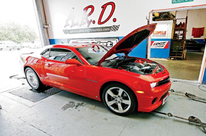
25. After re-installing the rest of the bits and pieces, ARD topped off the fluids and got to work on the tune. As is typical with most cam swaps, the drop in manifold pressure caused the L99’s computer to freak out and dump in extra fuel on the initial post-cam dyno pull. Consequently, ARD leaned out the air/fuel ratio from 11.1:1 to 13.0:1 using EFI Live software. Total ignition advance was set at 27 degrees. With the exception of a cold-air induction system and a set of long-tube headers, the L99-powered fifth-gen was stock before the cam install and laid down 365 hp and 384 lb-ft on ARD’s Dynojet. After the cam swap and custom computer tuning, those figures jumped to 406 hp and 374 lb-ft. That’s not too shabby for a day’s work, especially considering that the L99 still idled smoothly and maintained excellent street manners.
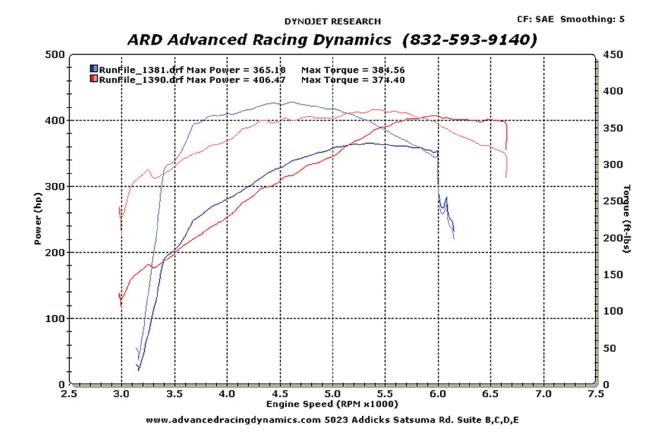
26. Longer-duration cams generally sacrifice some low- and mid-range grunt in order to increase top-end power. To fatten up the torque curve, ARD advanced the camshaft a few degrees using the VVT tables in the stock computer. While the larger cam gives up 5-10 hp between 3,000 and 5,200 rpm, it absolutely crushes the stock cam after that point. The stock cam starts fading after 5,400 rpm, but the COMP unit pulls hard to 6,700.