While installing an engine and trans into a chassis or car where it didn't originally belong isn't rocket science by any means, there are certainly right and wrong ways to do things. You'll nearly always want the engine to be located centrally in the car, unless you're building a cramped race car and need to offset the transmission for driver clearance, for instance.
Any carbureted engine should be mounted with the carburetor base level. But level with what? Level with the ground at ride height, which means you have to set the vehicle up at its intended ride height and level it side to side before even starting to mount the engine. Ride height may also be on a front-to-rear rake so take this into account when preparing the frame, or car if the body is on the frame. If you don't have the wheels and tires you'll be using, you'll need to know their overall diameter to ascertain the rake and ride height.
We knew what size wheels and tires we'd be using on the F-100 in this article, however, we set the frame on jackstands 2½ inches higher than ride height to enable the engine crane to fit under the crossmember. We then measured from datum points on each framerail to the floor and leveled the frame side to side. Additional shims were required between the frame and the jackstands to get the frame perfectly level, using a bubble level.
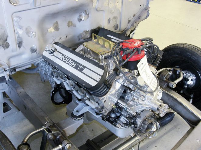
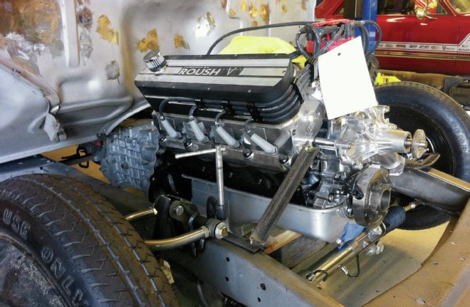
Once all this was done, we were finally ready to drop the engine in place and start working out our mounts. The Roush small-block Ford going in the F-100 fortuitously had a flat bottomed oil pan, meaning we were able to easily support it with blocks of wood during set up, but we also fabricated a pair of temporary stays to support the engine in place once we had it level and where we wanted it, with the transmission bolted to the block, and the carb base level in both directions. Other factors came into play at this point, such as making sure there was ample room to fit a fan between the engine and radiator (we installed the radiator to check), that there was clearance between the rear of the driver-side cylinder head and the firewall, and that there would be room for a steering shaft to clear the oil filter on the small-block Ford.
We should mention here that the pinion on the rearend should be set at the same angle as the trans tailshaft, so if the latter is 3 degrees downward, the pinion will point 3 degrees upward. However, as noted in last month's article on shimmy cures, the driveshaft should not be perfectly straight from trans to rearend, as the U-joints will run dry and fail. Some angle is advisable in the U-joints, but ensure the pinion and trans tailshaft are at equal angles.
Once all of the above was checked and correct, we used a transmission crossmember and engine mounts from Chassis Engineering to install our engine and trans. The crossmember is supplied over-long, and is available in varying amounts of drop. We selected the 4-inch dropped version, which worked perfectly in our application, and likewise the engine mounts, though they required some modification to fit our very wide framerails. As we stated at the beginning, such an installation isn't the most complicated fabrication job, but it's easy to get the measurements, angles, and geometry wrong. The fun part comes when trying to route headers and steering through the same space!
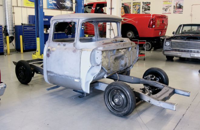
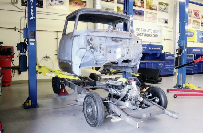
1. Here's our subject, a '56 F-100 big window. However, what we're about to do is the same regardless of the vehicle, as the steps to installing an engine and trans are identical.
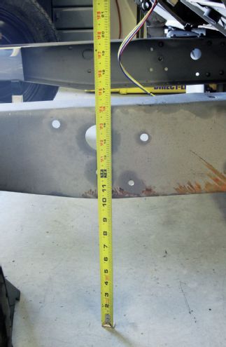
2. Once the frame was set at the desired rake, we measured from datum points on the side rails to the floor and leveled the frame side to side.
3. Side-to-side leveling required shims between the frame and jackstand. Ideally a frame would be set up on a frame table, but we don't have one. Irrespective of how level the floor is, the frame needs to be level side-to-side, hence the shims.
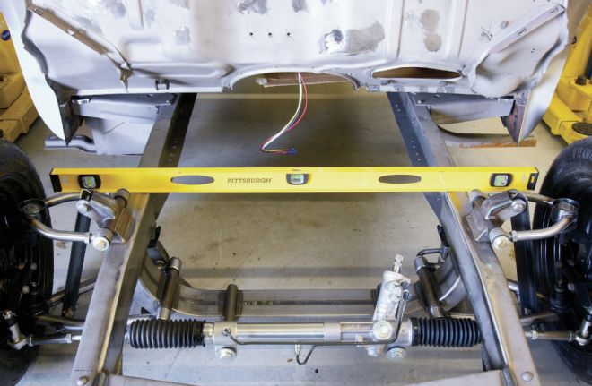
4. A bubble level was used to ensure the frame was level. We repeated this at the rear of the frame.
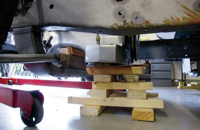
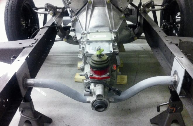
5. The engine was lowered into position. A number of factors will determine where it can be mounted, namely clearance between the pan and crossmember, clearance for the steering, and interference with the firewall, unless you cut this out to set the engine back. Once we determined where our engine would sit, it was supported on blocks of wood.
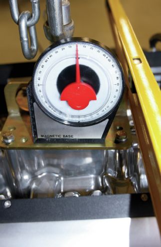
6. A magnetic angle finder was placed on the carburetor base and the blocks of wood added or subtracted until the base was level, meaning the engine itself was angled down toward the rearend by approximately 3 degrees.
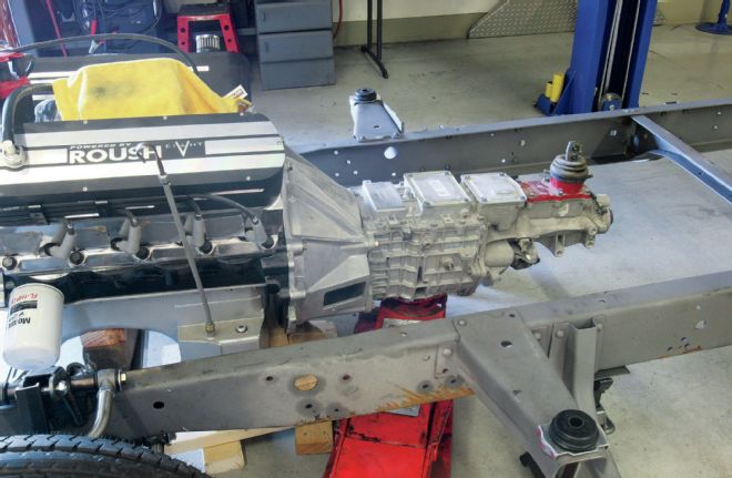
7. We next bolted the transmission, a Tremec TKO 600 five-speed, to the engine with assistance from a floor jack.
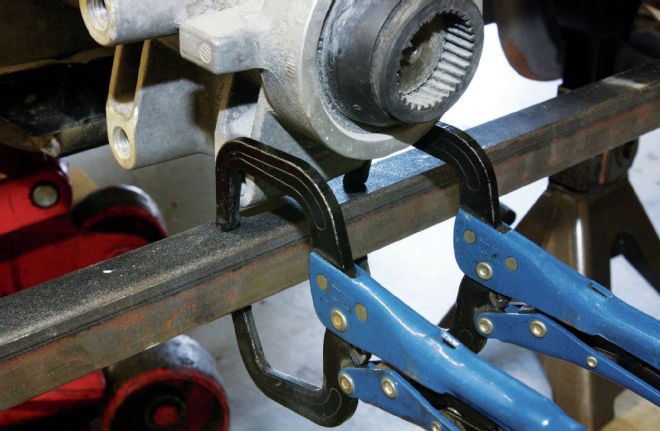
8. We clamped a length of 1-inch box section across the underside of the framerails, measured to find the center, and used clamps to ensure the tailshaft of the trans didn't move from this position.
9. Next we measured from the crank pulley boss to each framerail to centralize the engine.
10. A little adjustment was required to ensure the engine was both central in the frame and level side-to-side, but once it was...
11. ...we added these temporary angle iron brackets from the heads to the frame to ensure nothing moved while we fabricated the mounts.
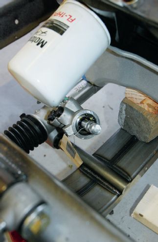
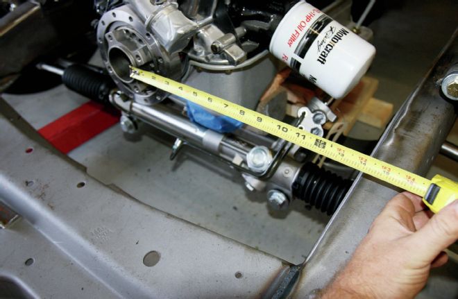
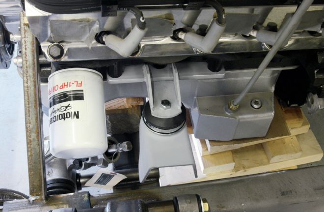
12. We had been a little concerned about clearance between the steering shaft and the oil filter, but our fears prove unwarranted, as can be seen.
13. We elected to mount the transmission first, and here's where access to the Direct-Lift two-post lifts in our Tech Center was invaluable, as we could raise and lower the body as often as required, with minimal effort.
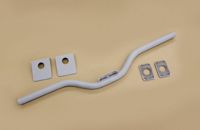
14. Chassis Engineering can supply transmission crossmembers in varying degrees of drop or no drop at all. We opted for the 4-inch dropped version, as the trans mounting pad was just slightly below the bottom of the framerails. The two plates on the left are boxing plates, while the pair on the right are for use if you wish to bolt the crossmember in place.
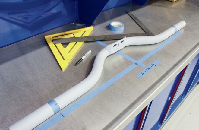
15. The crossmember is supplied over-long and needs to be cut to length. We measured the distance between the inside of the rails (33¾ inches in our case), marked the center of the crossmember using tape as shown, then merely measured half the overall width from the center out to each required cut.
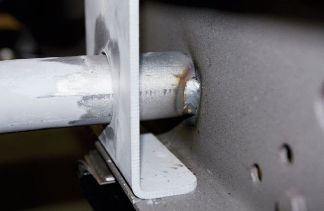
16. With the crossmember bolted to the trans, and the boxing plates in place (but not welded to the tube) it was tacked to the inside of the chassis rails.
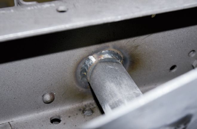
17. The plates were slid back along the tubes to allow access to fully weld the crossmember to the rails...
18. ...prior to welding the boxing plates in position. The crossmember is now fully welded to both the framerail and the boxing plate.
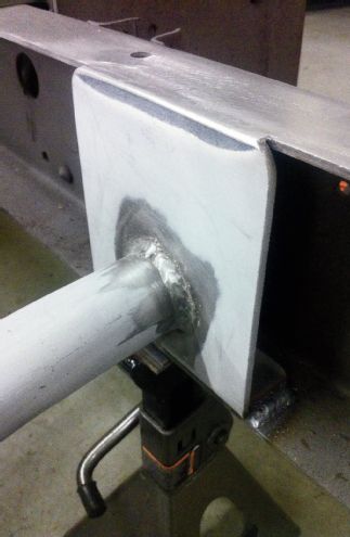
19. The finished trans crossmember install. Yes, we'll be boxing the remainder of the chassis at a later date.
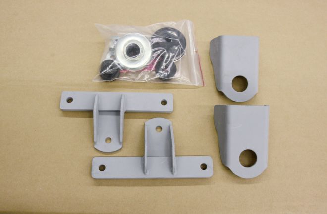
20. Chassis Engineering also supplied these small-block Ford engine mounts, the rubber cushion set, and chassis brackets.
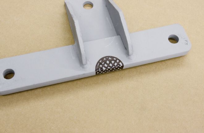
21. We had to remove a section of steel from the driver-side mount to clear a plug on our particular block. This was done using a holesaw and file.
22. We knew the width of our F-100 chassis was going to be a problem when using chassis brackets designed for cars, deciding to simply add 1¾ inches to each bracket.
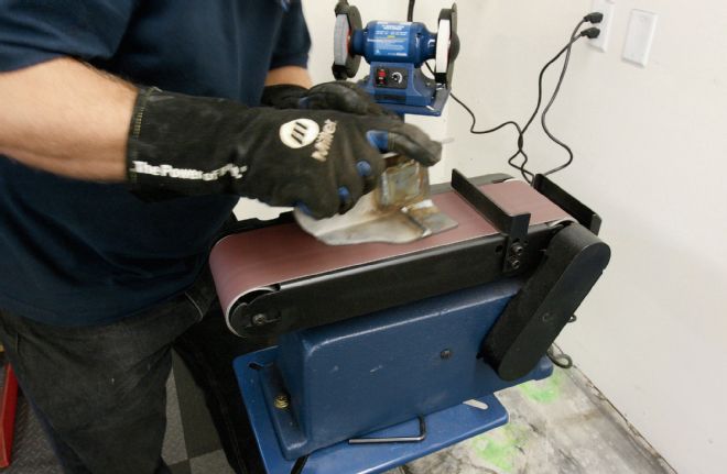
23. We extended the brackets using 3⁄16-inch steel, then sanded them to shape on the Eastwood belt sander in our Tech Center, prior to sandblasting.
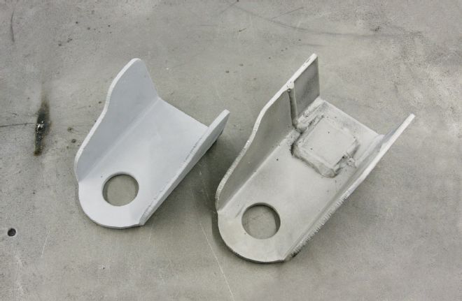
24. As you can see, we added a strengthening plate to the underside of each bracket, rather than simply butt welding them.
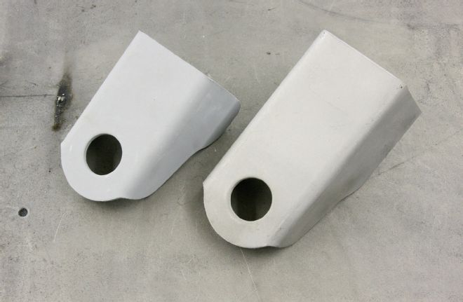
25. From the topside you'd never tell they didn't come that way!
26. One final check to ensure nothing has moved, and we're ready to weld the brackets to the frame.
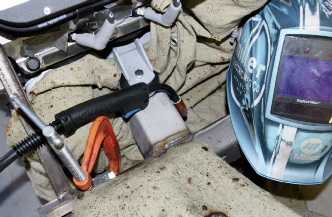
27. Using the optional 220V supply rather than 110V, our Millermatic 211 was more than capable of welding the brackets in place. Note that we used fire retardant blankets from Harbor Freight to protect the suspension, steering rack, and engine whilst welding.
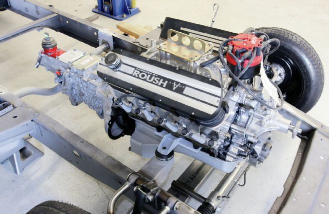
28. With the engine and trans mounted, we can now move on to headers and steering, then pull the motor to fully box the frame.