Venting a typical V-8 engine isn't a complex affair. A breather atop each valve cover is usually all that's needed. Of course, replacing one with a PCV valve to introduce a bit of vacuum into the system and to redistribute the unburned hydrocarbons back into the engine via the carburetor or throttle body yields a cleaner and much more environmentally friendly solution. Supercharged applications, however, can be a bit more finicky. Increased pressure in the crankcase can cause blow-by when using a traditional push-in style breather, covering that trick engine compartment with a fine mist of fuel-oil. Adding a PCV valve is a good idea, until a boost situation kicks in, at which time the internal check valve is forced shut, rendering the valve moot. At this point, instead of drawing fresh air into the breather and vanquishing the crankcase pressure through the PCV valve, the internal pressure is vented out the breather, possibly resulting in another oily blow-by situation. This usually happens when the engine is under load or at high rpm, which is when pressure builds up quickly and needs to be relieved the most.
The extreme solution to prevent all of this is to install a vacuum pump that continuously draws the pressure out of the crankcase. For most modest horsepower street engines, however, a vacuum pump is overkill, though it probably wouldn't hurt since drawing out the vapors and relieving any internal pressure is a good thing. What isn't a good thing is drawing too much out of the crankcase, which can be a problem in an engine that builds up significant crankcase pressure and is equipped with a vacuum pump. In this situation, the system can draw out more than just leftover hydrocarbons and vapor, but engine oil as well, requiring some sort of catch can to retrieve the gathered fluid.
It was with this in mind when it came time to design the crankcase ventilation system for our supercharged LS engine. I knew it was going to be important to let the engine breathe, but I also wanted to design a system that wouldn't fill the engine compartment with hydrocarboneous byproduct. And since proper ventilation is key to improved ring seal, oil scavenging, and windage, I wanted to be sure our supercharged LS had plenty of opportunity to breathe freely.
You'll recall a few months back when we dressed up our engine that we're using PML finned valve covers from Speedway Motors. These feature a 1-inch hole on the top of each designed to accept a push-in breather or PCV valve. Originally, my plan was to use a pair of PCV valves with the internal valve removed, one in each valve cover, plumbed to a Summit Racing breather tank on the firewall. With the valves removed, the PCV valves simply act as 90-degree elbows. This setup would be the "inlet" side of the crankcase venting system, while a traditional PCV valve mounted in the valley cover and connected to the intake would act as the "outlet" or recirculation side of the system. Fresh air would be drawn through the breather tank and down through each valve cover then out the valley of the engine, via the vacuum signal on the intake side of the PCV valve.
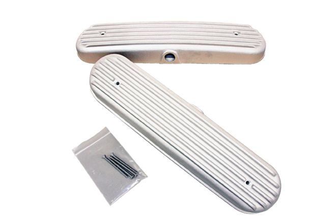
1. Here are the PML valve covers that we're using on the LS engine. Note the 1-inch hole at the top of each for a breather/PCV.
2. My initial idea of using a PCV, sans valve, would have worked perfectly. I just didn't like the possibility of blow-by occurring, especially since the valve covers and intake are as-cast pieces, which are especially hard to keep clean given their porous nature.
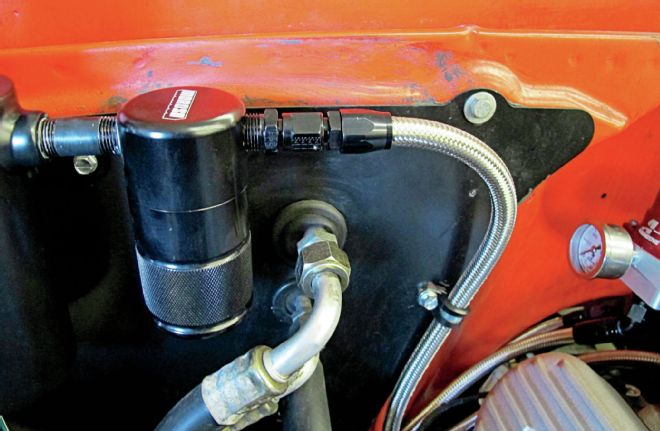
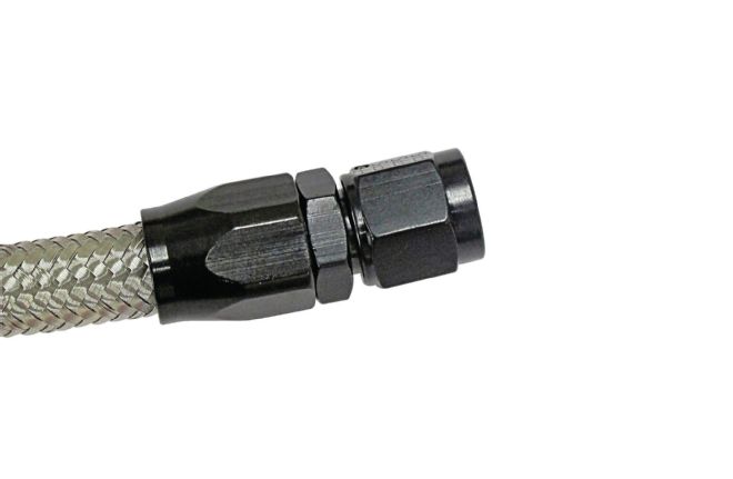
3. After whittling a small adapter out of aluminum and a little machine work, I came up with this nifty deal. The adapter mates to the valve cover via three #8 fasteners and accepts an Aeromotive ORB-06 AN fitting. A similarly sized and branded stainless braided line runs from each valve cover…
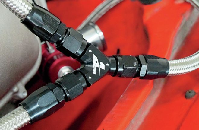
4. …to a "Y" fitting at the back of the engine.
5. From the "Y" fitting, a single AN-6 line runs to one side of a Summit Racing breather tank. This tank allows the engine to breathe freely while containing any oil that may be drawn up through the system.
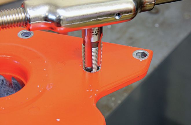
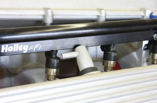
6. The second part of the crankcase ventilation system is related to the valley cover. Later-model LS engines come equipped with a PCV valve grommet location, but our LS327 crate engine did not, so it was necessary to drill and tap one.
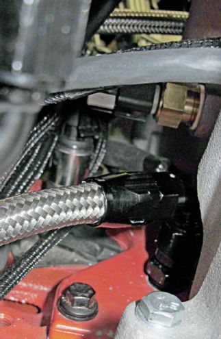
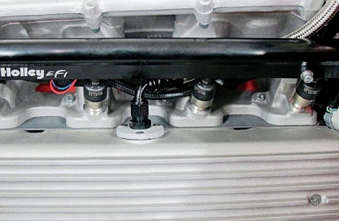
7. Once again, AN lines and fittings were used to connect the valley cover breather line…
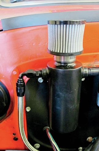
8. … to a Moroso air/oil separator. LS engines are notorious for drawing oil into the crankcase ventilation system, especially from the valley area of the engine so we opted to run the fumes through an air/oil separator before mating it to the breather tank, allowing the pressure to evacuate the system, sans oil.
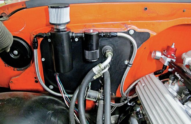
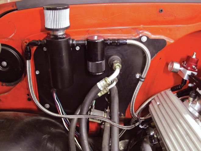
9. An overall shot of the system gives you a good idea how it all works. Basically, the valve covers vent through the breather tank on the left while the valley cover vent passes through the air/oil separator before venting out the breather tank as well.
The plan, though simple in its form, gave me a moment for pause since a push-in style breather or PCV valve still allows for a little blow-by at the grommet. Since I didn't want to deal with an oily mess as much as I could help it I decided to shift gears. The other problem is the aforementioned fact that when the engine makes boost, the PCV valve in the valley cover would be forced shut, thereby decapitating our crankcase ventilation system. After consulting a few engine builders much wiser than I, it was decided to forego a PCV valve entirely and allow the valley cover to vent to a catch can, just like the valve covers would now be.
This system would be fairly simple, but would rely on the pressure in the engine to relieve itself, since there wasn't a way—vacuum pump aside—to draw the vapors from the engine. It did however, have the benefit of three different outlets, ensuring that any pressure that could be trapped internally had a way out. I also came up with an alternative to the push-in PCV idea after messing with the Aeromotive fuel system mentioned elsewhere in this very issue, which I think will solve the blow-by dilemma that a traditional push-in breather/PCV can suffer from.
At the end of the day, I'm pleased that our engine is properly ventilated and sealed so as to not blow oil and vapor all over our engine compartment. Though it added a few extra components under the hood, I opted to live with them given the improvements to our setup they'll no doubt yield.
Easy AN Assembly
When it comes to assembling AN lines using braided hose, having the right tools is key. We found this Koul Tools AN Assembly Tool on Summit Racing's website. After building the fuel lines without one, we thought it a must-have for anyone who's going to equip their vehicle with braided hose.
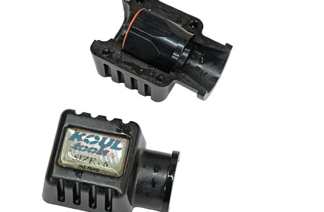
10. Each tool is size specific. Here, we'll be assembling AN-6 lines. First, a socket is placed inside one half of the assembly tool.
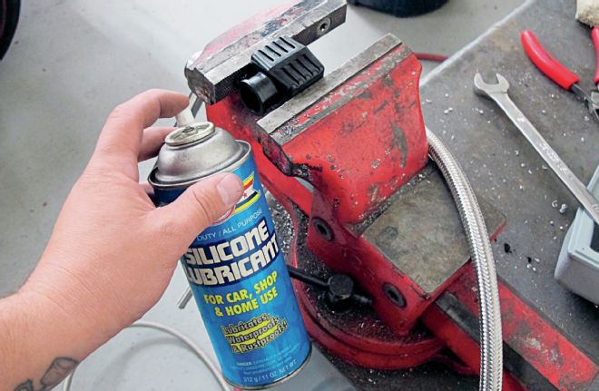
11. Then the two halves are assembled and placed in a vise. A little silicone spray will help the assembly.
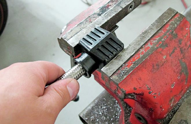
12. Next, the braided hose is pushed into the assembly tool. A little "twist o' the wrist" ensures it slides all the way home.
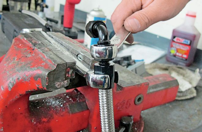
13. Next, the socket and hose are removed from the assembly tool and attached to the insert.
14. And there you have it, one AN fitting assembled the "Koul" way!
An Alternative Oil Fill
With the new crankcase ventilation system complete, it was painfully obvious that I would have to come up with an alternative method to filling the engine with oil. Equipped with push-in style breathers, it's a simple task of pulling a breather out of its grommet and adding oil. With our ventilation system "hard lined" to each valve cover however, it's not so simple. I didn't want to have to remove the AN line every time a little "top off" was due as that would require carrying an AN wrench in the truck as well as a funnel. The solution needed to be simple and easy, requiring nothing but a quart of oil and a free hand.
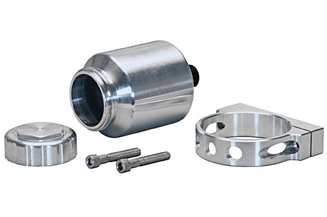
15. Looking no further than the existing clutch master cylinder, I made a quick phone call to the guys at Wilwood to see if they offer a matching stand-alone reservoir. It turns out, not only do they, but they also offer a slick billet mounting bracket.
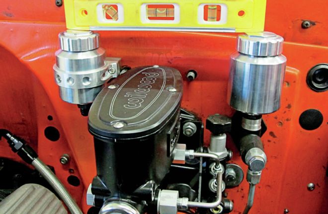
16. The mounting location only needs to be higher than the valve cover so that gravity will kick in when it comes time to add oil. I decided to mount the Wilwood oil fill cylinder on the opposite side of the brake master, effectively flanking it in a reservoir sandwich.
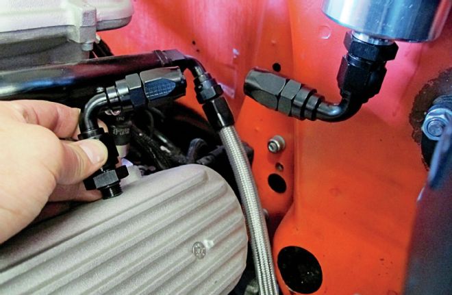
17. The outlet on the reservoir is 3/8-24, so it's a simple matter of mating an AN-6 elbow before figuring out how to run the line from there to the valve cover.
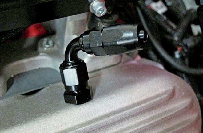
18. Another 3/8-24 fitting/AN adapter tapped into the top of the valve cover and mated to an AN-6 90-degree elbow will act as the inlet side of the line.
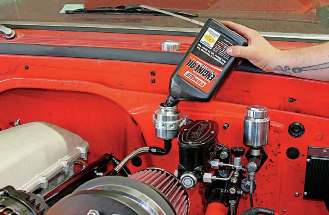
19. With a short section of stainless braided hose assembled to both fittings, we now have a trick oil fill setup that makes quick, easy, and most important of all, clean oil filling.