Ask the average performance enthusiast about the Ford's modular family engines and you'll usually hear a barrage of preconceived and misguided notions: The engines are too small. Those things don't make torque. You need a blower to make power with one of those. The bore is too small for real horsepower. Ford blew it when it phased out the good old Windsor small-blocks. The opinions go on and on, but the reality is that the mod motor, introduced in 1991, has been one of the most successful and innovative series of V-8 engines in production history.
Notable for its single or dual overhead cam layout, the mod has been produced in two-valve, three-valve, and four-valve variations, with iron and aluminum blocks, in a staggering range of displacement and horsepower output. It is safe to say that the mod has been offered in a broader range of permutations than any engine in history. There is little debating the mod's success as a production engine. Still, outside of modifying late-model vehicles, suspicion of the mod seems to linger in the hot rodding world.
When we revised the rules for the 2013 AMSOIL Engine Masters Challenge, one of the changes from previous competitions was to remove the prohibition on four-valve engines. We wondered how many would take note of this revision and take up the mod as the basis for a completion build. From a classic engineering standpoint, the advantage of a four-valve layout has been documented since the early part of the 20th century. Still, we had to wonder how common misconceptions might influence the acceptance of the mod engine in our competition. After all, this was a contest of normally aspirated power—one in which low-end torque is a major contributor to score—and finally, there was the hurdle of a 400ci minimum displacement. This is not the normal venue of the mod Ford.
 To serve as a foundation, Kaase started with a production Ford M54A aluminum block as a base. The stock crank was replaced with a Bryant billet 4.700-inch stroke unit. That huge stroke length played a major role in making this the biggest engine of its type—ever.
Jon Kaase of Jon Kaase Racing is an engine builder known for innovative thinking and exceptional engine-building talent. Kaase saw an opportunity in the four-valve Ford. "I started thinking about it right after the rules were announced last year at the press conference at the PRI show. It just looked like if you could make it big enough, it would be an interesting project. I thought it could be very good, but I wasn't sure, since I didn't know that much about them or what parts existed. I started to do some research because I didn't have any history with that engine whatsoever."
Job one was to explore the possibility of increasing the displacement to meet the 400ci requirement. Kaase explains, "I really didn't know how much stroke you could put into one, since nobody really had taken these engines to this kind of displacement. I had to see if big displacement was physically possible, but in the end it turned out to be pretty easy."
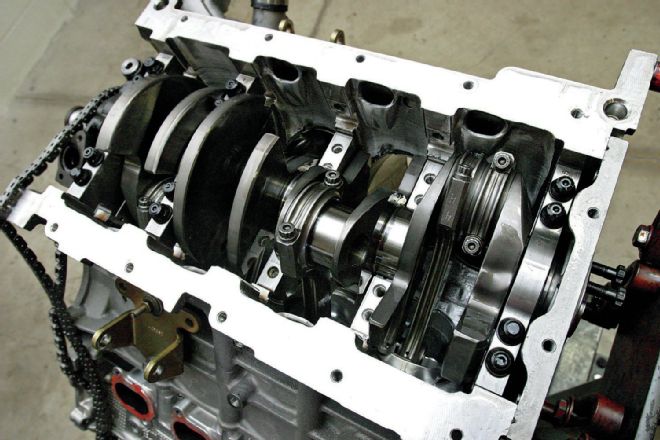
Kaase began by looking at block selection, considering both the iron and aluminum blocks available. Determining the iron blocks to be more limited in bore size, Kaase went with an aluminum 5.4 production block as the basis. He elaborated on the block, "The aluminum block has Siamese cylinders and does not come with a sleeve in it. It comes with a thin plasma coating as the liner in the cylinders. I bored it out, designed some thin 0.050-inch wall sleeves for it, and ended up with a bore size of 3.720 inches." Kaase had a custom billet crankshaft cut by Bryant, using the OEM journal diameters and a 4.700-inch stroke. Filling the bores are custom Diamond pistons built from a model made by Kaase for this application, with Eagle 6.658-inch rods connecting the internals. The combination yielded a displacement of 409 ci, making it the largest known engine of its type ever built.
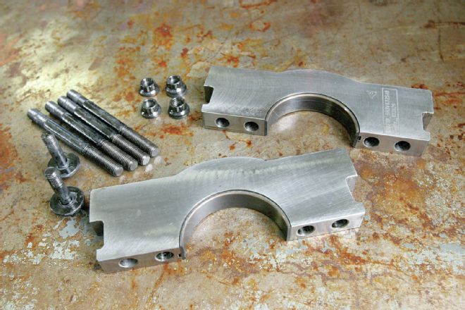 Factory six-bolt cross-bolted main caps are standard equipment for these blocks, giving bulletproof bottom-end strength. Kaase added ARP fasteners throughout.
Exotic Top End
Clearly, the defining component of the engine is the four-valve DOHC cylinder head arrangement. Ford had several variations of these four-valve heads, with these being the Ford GT–style castings. Kaase actually acquired this set from Roush Yates as takeoffs from a Daytona Prototype endurance-racing engine. The heads were already CNC ported, and Kaase actually acquired two sets, giving him a set of heads to experiment with. As he tells us, "I worked on one of the sets, putting a little bit bigger intake valve in it. That is the set of heads I ended up running, but I really didn't see much improvement. To be honest, I did hardly any headwork, almost nothing. I did put the bigger valves in, but the other heads made every bit as much power."
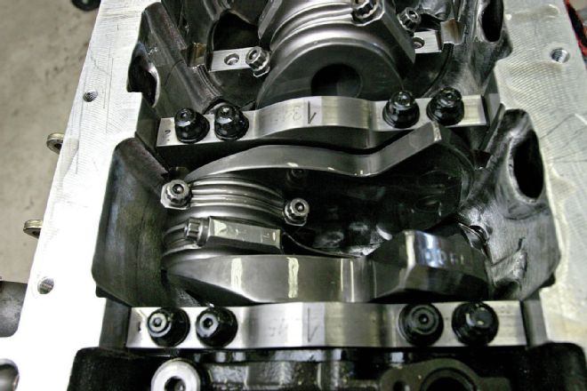 Due to the robust installation, which ties in the whole lower structure of the aluminum block, the factory steel caps provide plenty of strength.
The heads and cams were essentially a team, and optimizing the combination required unique considerations with the DOHC arrangement. Unlike a conventional pushrod engine, the DOHC engine opens the door for a wide range of variables and adjustments, with separate intake and exhaust cams allowing experimentation on centerline angle individually. Kaase described some of the theory and testing: "With all the valve area they have, at about half-lift there is a lot of valve opening area, so these engines will run about 20 degrees less camshaft. If you can run a lot less camshaft, it would seem to reason that it would make a lot more torque down low. With the very long stroke and the short camshaft, I figured it would be very good down low if it had the right manifold. Really, these factors influenced my decision to try the four-valve in the competition."
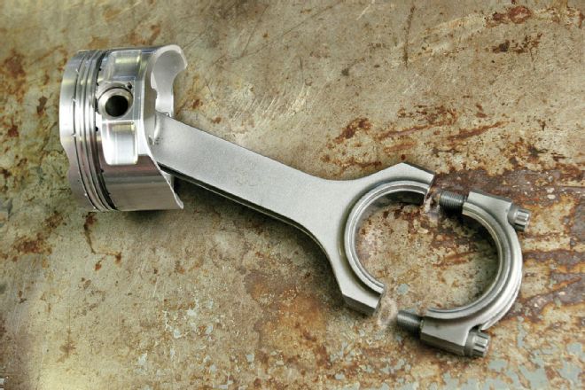 Kaase retained the stock rod length but opted to upgrade to Eagle H-beam rods. The pistons are custom units modeled for the application by Kaase and manufactured by Diamond.
Kaase continued, "I talked to Comp Cams and they helped me out with ideas on the duration. I had two different sets of cams, and in the end had one set reground, so I had quite a few variations to try out. I tried a lot of different things, and it is basically trial and error. I started out with the biggest cams, and I had those cams in every possible position, with wide lobe separation, narrow separation, way advanced, way retarded, just everywhere, because they are easy to move. It was pretty consistent that the intake wanted to be at around 98 degrees centerline, and when I finalized everything, the exhaust was the same; it wanted to be at 98 degrees. You can say I was at 98-degree lobe-separation angle and zero advance. One observation I made from the EFI cam sensor, which reads in degrees, is that from 3,000 to 7,000 rpm, the cams will retard about 5 or 6 degrees. You couldn't ask for anything better than that. It is just what you want."
While the four cams seem exponentially more complex, Kaase tells us, "It wasn't that hard. For this contest, the intake lobe is going to want to be between 92 and 100 degrees. That will work the best, especially with a compression ratio limitation. With 11.5:1 compression, the engine still produced about 240 to 250 psi cranking compression, which helps down low. At the same time, the later you open the exhaust, the better off you are going to be down low. So having the exhaust in at 98 degrees, it opens late and that helps you. It wasn't that hard to figure out; I knew about where it wanted to be, and that's about where it ended up. On these kinds of engines, especially with their good exhaust flow, it wasn't going to need a lot of exhaust cam. Initially, I had less exhaust than intake, but I ended up with them both the same."
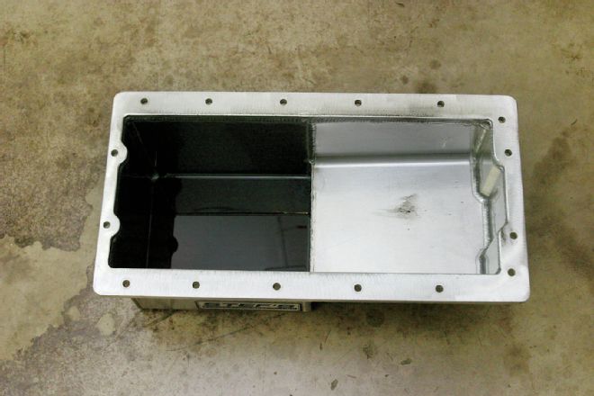 With the engine’s excellent factory oil control system, including the drainback provisions and windage tray, the custom Stef’s oil pan is a very simple design.
Nothing really outlandish was needed in the valvetrain, as the factory Ford components proved to be excellent. As Kaase explained, "The rockers have a roller wheel and 1.8:1 ratio and it really works out well. I never had any trouble with the hydraulic adjusters. I tried shimming them and making them almost solid, and it really didn't matter. They worked fine no matter how you did it. In the end, I just ended up removing the limiters and running them as original. I never had a bit of trouble as you might have with a hydraulic. With these engines, the spring loads are much more modest than we are used to with the larger valves of a pushrod engine. I used Comp Beehive springs with loads of 115 pounds on the seat and 280 pounds open. If you look at the valves, they really weigh very little and they have titanium retainers on top of that, so the relatively light spring loads offered all the control required in this operating rpm range."
The induction system consisted of a factory 2000 Mustang Cobra R intake manifold with an Accufab throttle body. This rather rare intake manifold is a two-piece unit, with laid-over individual runners enclosed in a separate plenum housing. Kaase found this intake to offer the broadest powerband. "When I first got it running, I had a four-barrel intake manifold, and the engine made as much as 2 hp per cubic inch. The thing is, for the EMC competition, you need to have very good low-end torque to score well, so it goes to show that even with everything else going for you, with one wrong component, it still will not give the power curve you want. We had to give up a lot of that upper-end power to make it better down low."
Kaase continued, "The manifold is a two-piece design that is hard to find, especially the tops. On the bottom, I ported it a little bigger, but I don't know if that really mattered because I started out with it unported, and when I ported it, it didn't really help. It is pretty small, but it still makes pretty good power. The biggest thing I did to it was shorten the runners a little bit, because they were really close to the sides of the top cover. There were a few places where the entry to the runners was half an inch from the top cover. I cut about an inch or more off the runners and angled them back. I made radius entry rings out of aluminum plate to give the runners a good entry. The shorter runners really helped from about 4,000 rpm and up, mostly because the stock runners were just too close to the top cover wall."
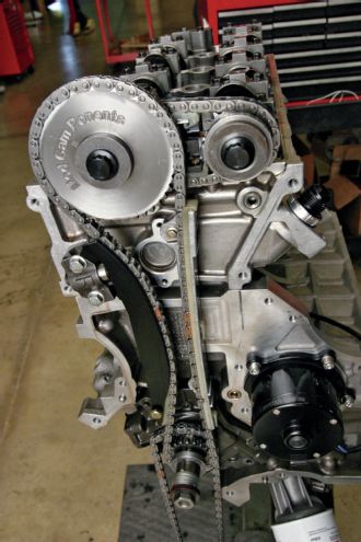 The DOHC mod uses a long chain from the crank to drive the cams at the top of the heads. Kaase tells us this arrangement actually pulls a few degrees of cam timing out at high rpm, which is a benefit to high rpm power.
The induction development continued with the fuel injection, as Kaase details: "The other thing I did is experiment with the injector position. When the injectors were in the original position, there was only about 5 lb-ft of difference, but 5 lb-ft is the difference between a win and loss at the AMSOIL Engine Masters Challenge. With the injectors in the stock position, it was easier to get the tune correct, and you could see it was clean in the plenum. When I moved the injectors up the runners like I ran them, you could tell it had more standoff, and you could see the fuel staining in the plenum. It was much harder to tune, and I had to really chase the fuel curve for each cylinder through the rpm range, with the greatest difficulty being below 4,000 rpm. We tried it with the injector at the mouth of the runner, but it didn't work out well. The pulses would throw the fuel out of the port and it would go everywhere."
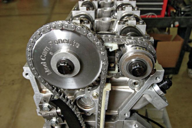 A short chain linked from the exhaust cam drives the intake cam. This layout allows the centerline of each cam to be adjusted independently, which also allows the lobe-separation angle to be altered.
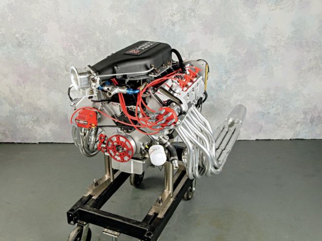
While the Kaase mod motor is an extraordinary piece in just about every aspect, the crowning achievement has to be the unique "16-pipe" exhaust headers. The system takes advantage of dual primary tubes from each cylinder, a setup we confess to have never seen on any V-8 engine. Kaase tells us, "I got the idea looking at a Buell V-twin racing motorcycle. At first glance, seeing the four pipes, I presumed it was a four-cylinder, and looking closer I realized it was a twin. It was a system that I felt could be put to use on the Ford four-valve. I had only built one set of headers decades ago, but something like this was interesting enough to try. My first set was based on the idea of using a long and a short primary on each port, looking to produce a wider tuning window, but it didn't really work out compared to a conventional header. The final design proved to be functional in testing, showing advantages at certain rpm points compared to a more conventional header. Actually, there were quite a few further variations I would have like to have tested, but the time was not available. You could play around with something like this forever."
Power Play
There's no doubt that a Kaase mod motor is an unusual engine combination. With a displacement bigger than any other V-8 mod motor, a huge stroke and tiny bore, four cams, 32 valves, 16-pipe primary headers, a factory intake with injectors shooting up toward the plenum, all based on a stock Ford block and heads, and turning an essentially factory valvetrain, this thing was an enigma. At the 2013 AMSOIL Engine Masters Challenge, Kaase's radical mod held a crowd of onlookers simply slack-jawed at its sight. That astonishment continued as the engine went into the dyno test cell and began spinning out power. At the bottom end, the numbers were staggering, with more than 600 lb-ft of torque on the dial at just 3,400 rpm. That, folks, is an outstanding level of torque at peak for an engine of this displacement. The dyno's strain gauge kept stretching up to a peak of 666 lb-ft at 5,100 rpm. The resultant specific output of 1.63 lb-ft per cubic inch is unheard of, especially considering an 11.5:1 pump-gas engine. Convinced that a four-valve mod can indeed make torque?
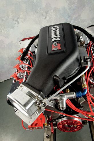 Delivering the airflow to the heads is a rare 2000 Cobra R intake manifold, which is a two-piece design incorporating a removable top plenum cover.
On the power side of the equation, 720 peak horsepower was recorded, equally impressive considering the engine was built for the broadest possible power curve at the EMC competition. Kaase had already seen well over 800 hp in pre-event testing with a combination favoring top-end output. Still think you need a blower to make power from one of these mod Fords? Think again. Frankly, the Kaase mod gathered up all of those preconceived notions about these modern Fords and annihilated them in an incredible display of pure engine power, taking his fifth AMSOIL Engine Masters Challenge Championship in the process.
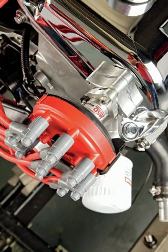 While these engines typically run coil-on-plug ignition, Jon selected a distributor retrofit run directly from the camshaft.
BY THE NUMBERS 409 Ford Modular Four-Valve Bore 3.720 inches Stroke 4.700 inches Displacement 409 cubic inches Compression ratio 11.4:1 Camshaft Custom Comp Hydraulic Roller Valve lift 0.625 inch Duration 230 degrees at 0.050 Rocker and ratio Comp 1.8:1 Piston rings Total Seal 0.043 x 0.135 3 mm Piston Diamond Forged Block OEM Production Aluminum 5.4 M54A Crankshaft Bryant Rods Eagle 6.658 inches Cylinder head Ford GT Chamber Volume 59 cc Intake valve diameter 1.510 inches Exhaust valve diameter 1.260 inches Intake manifold Cobra R EFI FAST DFI Header Kaase 16-Pipe Ignition MSD Damper Innovators West
ON THE DYNO 409-Cubic-Inch Ford Four-Valve Jon Kaase Racing Engines DTS Powermark Engine Dyno Tested at UNOH RPM Torque Horsepower 3,000 515.1 294.2 3,100 556.2 328.3 3,200 576.2 351.1 3,300 592.7 372.4 3,400 608.2 393.7 3,500 616.3 410.7 3,600 615.6 421.9 3,700 615.3 433.4 3,800 621 449.3 3,900 631.5 468.9 4,000 643 489.7 4,100 652.3 509.2 4,200 658.1 526.2 4,300 657.9 538.6 4,400 654.6 548.4 4,500 651.3 558 4,600 649.7 569.1 4,700 651.5 583.1 4,800 655.3 598.9 4,900 660.1 615.9 5,000 664.3 632.4 5,100 665.9 646.6 5,200 665.2 658.6 5,300 658.9 664.9 5,400 652.8 671.2 5,500 645.9 676.4 5,600 639.5 681.9 5,700 633.7 687.7 5,800 627.2 692.7 5,900 622 698.8 6,000 617.3 705.2 6,100 612.1 710.9 6,200 606.2 715.6 6,300 599.3 719 6,400 590.8 720 6,500 580.3 718.2 6,600 567.5 713.2 6,700 552 704.2 6,800 536.2 694.3 6,900 519.7 682.8 7,000 505.6 673.8
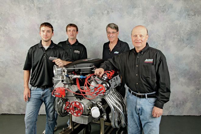 Kaase and the crew from Jon Kaase Racing took the four-valve mod motor to an unprecedented fifth AMSOIL Engine Masters Challenge victory.