You most likely know that fuel tanks need ventilation in order to allow the fuel to continue to pump without causing a vacuum. This can either be through the gas cap itself, or via some sort of breather tube. The latter is usually routed up higher than the tank, before exiting below it, in order to prevent spillage if the tank is overfilled, or possible siphoning.
My lakes-racing Model A roadster pickup uses an Aeromotive 6.2-gallon aluminum fuel tank, with an internal 340-lph Stealth fuel pump. It has four ports: the ORB-8 outlet, an AN-8 return line port, and two AN-8 vents with rollover valves. I'd plumbed the latter two with oversize rubber tubing and hose clamps as a stop-gap measure when I first raced the car, but figured I'd do the job properly this time around, using AN-8 fittings and 5/8-inch braided hose to match the rest of the fuel system.
I also needed a pair of actual vents, rather than simply leaving the hoses open to the atmosphere. Eddie Motorsports came to the rescue with a cool pair of stainless steel marine vents. Designed for boats, they can accommodate a thick hull, and can also be bolted through sheetmetal, as in our case. They're designed for 5/8 rubber hose, so we welded some 1/2-inch OD stainless tubing to the ends, which would accept adapters to fit stainless braided hose.
Speaking of braided hose, this is a good opportunity to give a brief overview on how hose ends should be attached to braided hose, and show a simple tool that makes assembly a breeze. Just remember to use a little grease for lubrication, though try to keep it out of the fuel lines. These are vent lines, but we still blew them clear of debris using an air line after assembly. This step is even more important with actual fuel lines!
 1. Koul Tools (available from Speedway Motors) make quick and easy work of assembling AN hose ends. This kit (PN 681) covers AN-6, -8, and -10.
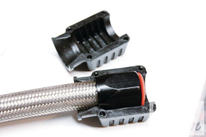
 2. The nut part of the hose end that the braided hose fits into is placed in the funnel. Disc spacers are provided to ensure the nut is a secure fit (arrow).
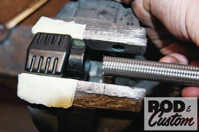
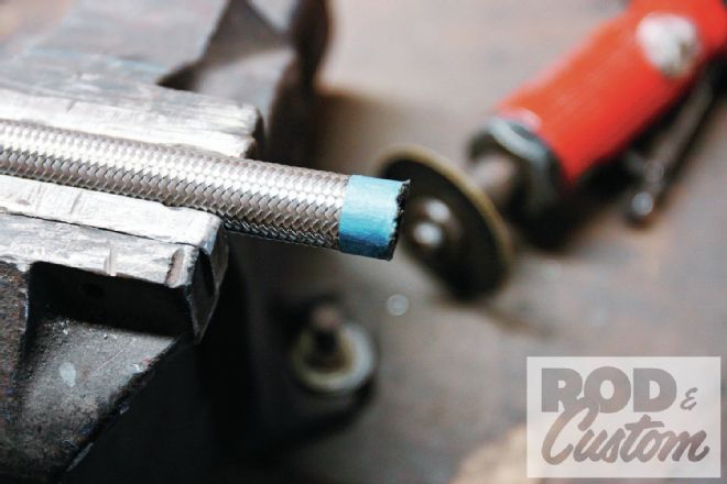 3. Tape is placed around the braided hose while it is cut to length, to prevent frayed strands, which would make the following steps harder. We used a cutoff wheel to cut the hose.
 4. With the funnel assembled in a vise, and the entrance lightly greased, the hose (once the tape is removed) is twisted into place until it bottoms out in the nut.
 5. Voíla! The hard part’s done, with no frayed braiding and no punctured fingers!
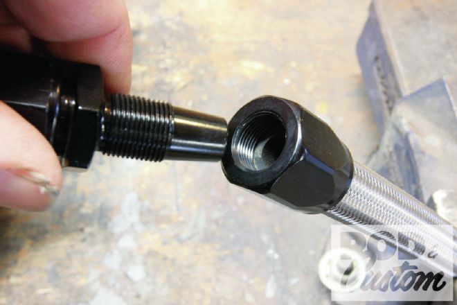
6. Assembling the hose end; the tapered section fits inside the rubber inner hose, which you can see bottomed out in the nut (arrow), and as the thread is tightened the taper causes the hose to expand inside the nut, ensuring a leak-proof and secure seal. Again, lubricate the joint prior to assembly.
5. Voíla! The hard part’s done, with no frayed braiding and no punctured fingers!
6. Assembling the hose end; the tapered section fits inside the rubber inner hose, which you can see bottomed out in the nut (arrow), and as the thread is tightened the taper causes the hose to expand inside the nut, ensuring a leak-proof and secure seal. Again, lubricate the joint prior to assembly.
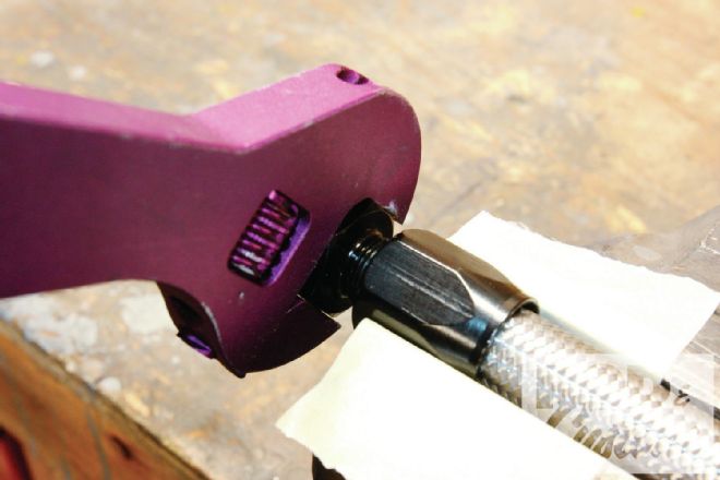 7. Specialist aluminum wrenches are available to prevent scratching anodized AN fittings, though we used this aluminum adjustable wrench from Speedway. Aluminum vise jaws are also available, though masking tape will also prevent scratches.
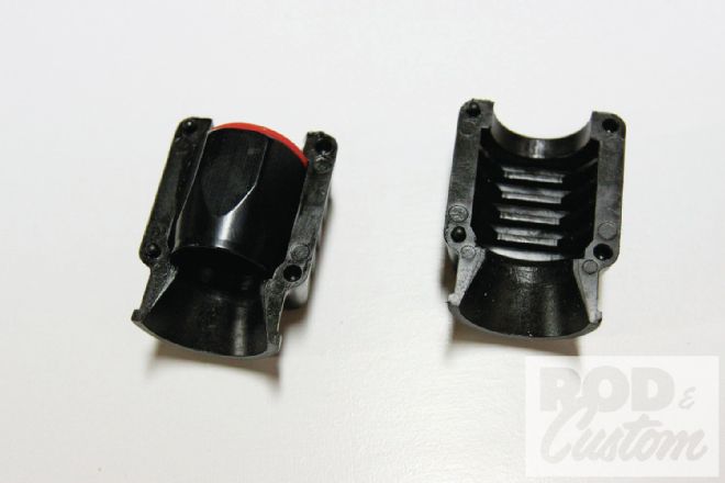
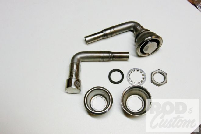 8. At the other end of our gas tank vent hoses, we’re using a pair of these stainless steel flush-mount vents, designed to accept 5/8-inch rubber hose. We welded short lengths of 1/2-inch stainless tubing to them to accept hose fittings. The upper vent is assembled, the lower shown in its component parts. They’re available from Eddie Motorsports.
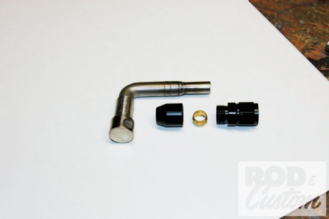 9. While the majority of our AN hose ends came from Aeromotive, we sourced the fittings to attach the braided hose to the vent from Summit Racing. These aluminum fittings use a screw-together compression fitting that is compatible with low-pressure applications, designed for aluminum tubing. However, as this is a vent application, we’re happy with using them. If fuel is ever in these lines, the car is upside down and the tank’s rollover valves will have failed!
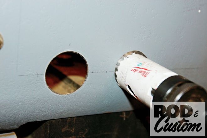 10. A couple of 1 3/4-inch holes in the pickup bed side courtesy of a holesaw …
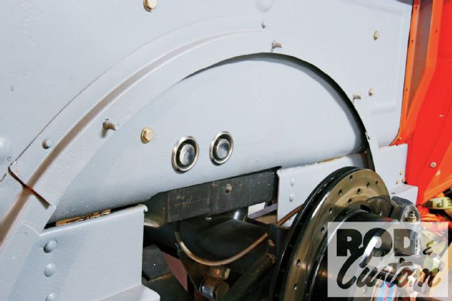 11. … and the vents are mounted. We chose this location behind the right rear wheel as it’s as far from the driver as possible without running braided hose to the very rear of the truck, and shouldn’t get salt flung into the vents, thus blocking them.
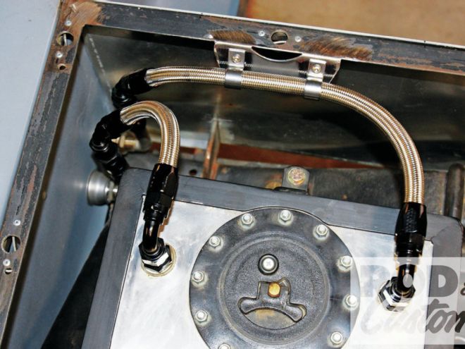
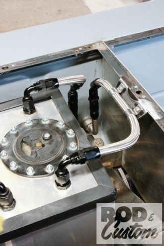
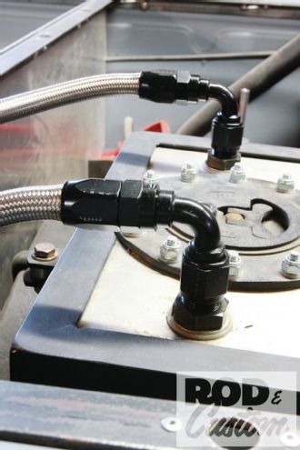 12. A pair of 90-degree AN-8 hose ends connect the braided hoses to the rollover valves in the 6.2-gallon Aeromotive tank.
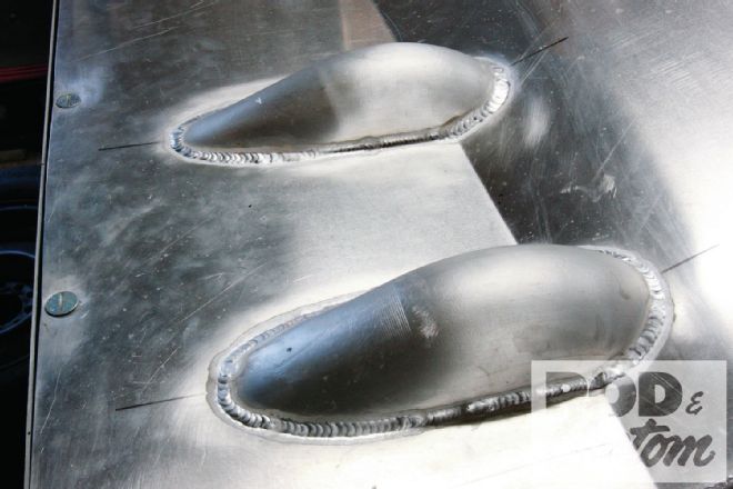 13. These blisters in the tonneau cover allow space for the hoses to exit the rollover valves and pass down behind the tank.
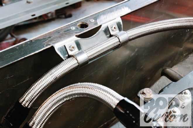 14. The longer of the two vent hoses prevented the tonneau from sitting flush with its mounting flange, so to route it lower and prevent chaffing in the future, this bracket was fabricated and welded in place. There are 5/8-inch stainless clamps from Kugel Komponents to secure it in place.
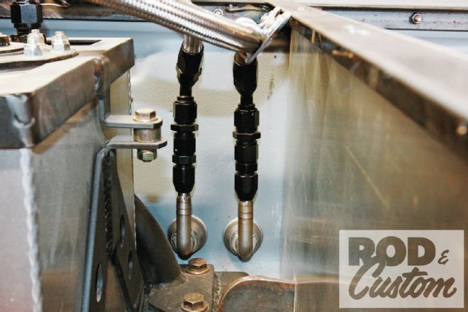 15. The braided hose attaches to the vents by 45-degree hose ends, adapters, and the compression fittings. Male compression fittings would have meant using fewer parts, but we had these “in stock”. We’ll rectify the unequal lengths (we mistakenly cut the stainless tubing on the vents to different lengths) when it all comes apart for paint.
 16. Tidy, functional, and another job off the list!