At Circle Track, we're all about helping you do more for yourself. But sometimes that's just not realistic. That's not casting doubts on the intelligence of our readership. Just like your mom, we believe you can learn to do anything yourself. It's just that many things necessary to go racing require expensive equipment that's simply out of the budget of most hobby-level racers.
This is especially true when it comes to the expensive machining equipment required to cut, plane, and hone the cylinder heads and engine block to spec, making it ready for assembly. The machinery required to perform those tasks properly is prohibitively expensive, requires a serious commitment in terms of shop space and supporting equipment, and takes a lot of time to learn to operate properly. So, we'll leave that to the professionals and enjoy going racing instead.
But that doesn't mean there aren't things you can do to make sure your machine work is being done properly. Better than that, we're going to show you how to make sure your cylinder head machinist isn't just doing an adequate job, but superior work. After all, this is racing, where everyone is striving to be the best of the best, not rebuilding the motor in a work van.
Many things necessary to go racing require expensive equipment that's simply out of the budget of most hobby-level racers
The area we're tackling today is the machine work done on the cylinder heads to give the valves a proper home. Both the intake and exhaust valves have an incredibly tough job, operating at seven- to eight-thousand rpms (or more) for extended periods with cams that are more aggressive than ever before—and getting more aggressive every year. Now add the fact that the valves most racers are using use the maximum diameter with the minimum stem size the rules will allow (usually 11/32-inch for typical Saturday night racing rules) to get the most amount of flow through the engine with minimum weight, and you can see why a ruined engine thanks to a dropped valve is an all-too-common sight in circle track racing.
If you're a regular reader of Circle Track you will probably recognize the name "KT Engine Development." We've worked with KT Engines for years because its engines win races and the company is confident enough in its abilities that it doesn't bother blowing smoke.
While working on other stories at KT Engines, we've noticed cylinder head specialist Kevin Troutman goes about the process of prepping cylinder heads a little bit differently than most other shops. We've pestered him for a while to share his process, and it may cost us a lunch or two, but we finally broke him down. It's all about making sure each valve is at the same depth on each head and uses minimal spring seat shims. That sounds simple enough, but the difference here is Troutman is much more concerned with the valve location at the bottom of the heads (the combustion chambers) than the top, where it's much easier—and more common—to measure.
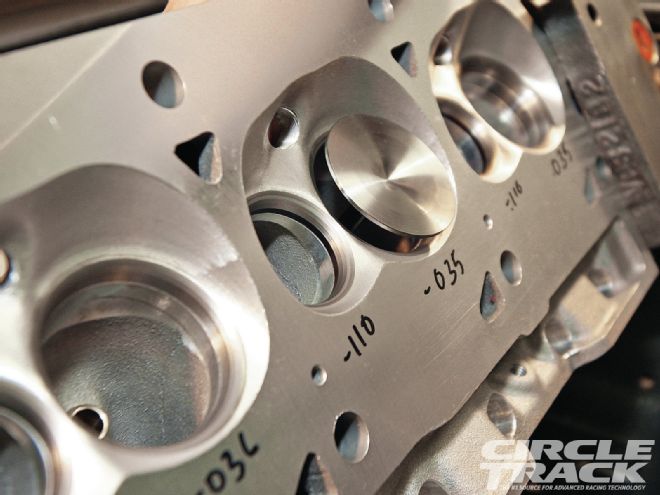
 ▲ A quality valvetrain is about more than just lashing the valves. It begins with precision machine work to create a good working environment for the valves.
This story is all about showing you why. Now you can check with your engine builder/machinist to make sure he is taking the same steps to ensure maximum precision. If your machinist isn't already doing this you can encourage him to begin, or better yet, find someone who is because then you know you're dealing with an outfit that refuses to take shortcuts.
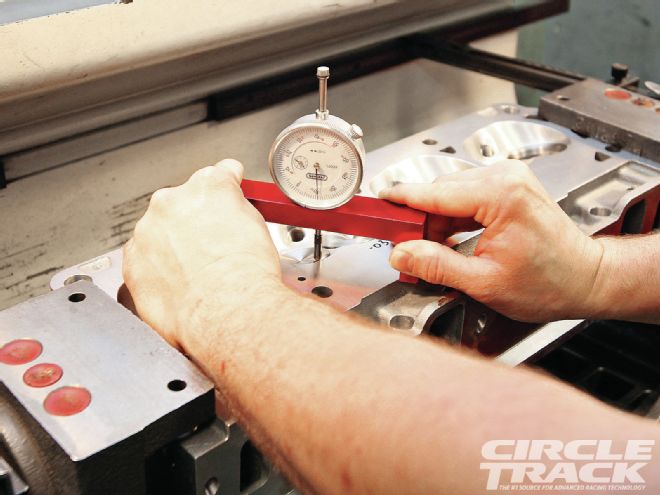
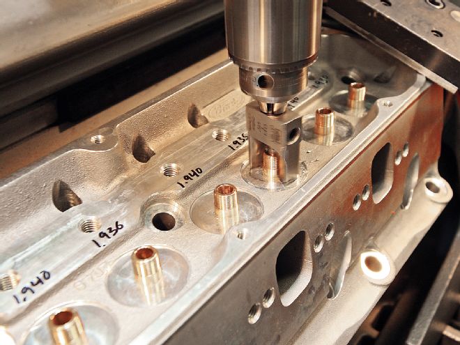
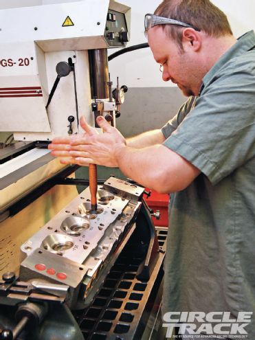
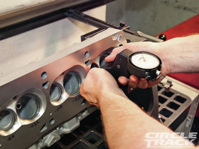
[1] Immediately after cutting the seats KT Engine’s cylinder head specialist Kevin Troutman measures the valve heights from the combustion chamber side of the head. That’s because the most important part of the valve, he says, is the face and not the stem. For example, engine builders almost always check their piston-to-valve clearance at the No. 1 cylinder. But if that valve is high compared to one of the other 15, then one of the valves you didn’t check can be dangerously close to the valve, which can lead to engine damage if the motor goes into valve float. The only thing required to check your valve heights on this side of the head is a dial indicator in a deck bridge
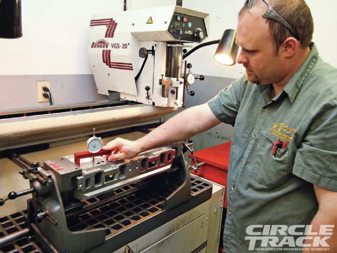
[2] If the cylinder head hasn’t been freshly decked, make sure to zero out your bridge gauge on a surface you know is completely flat. Even if the engine has never overheated, if the cylinder head has been on a running engine the heat can start the warping process.
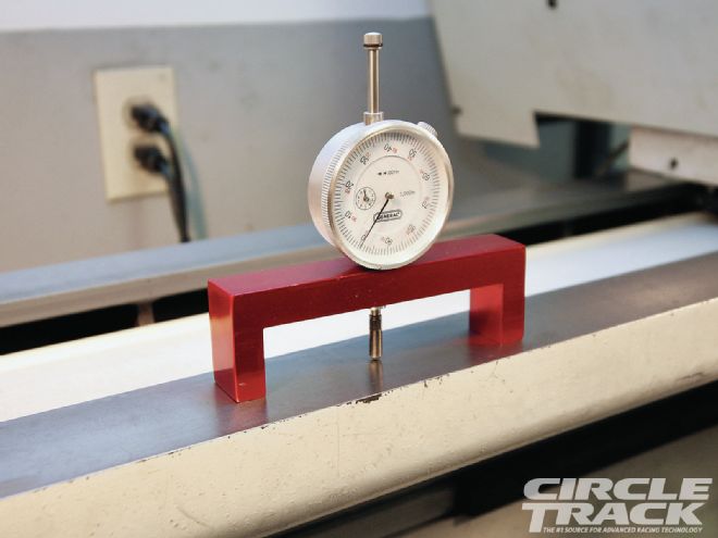
[3] Place the deck gauge so that both feet are on the deck of the block and the dial indicator is over the edge of the valve that’s on the tall side. On both a Chevy or Ford this will be the edge of the valve closest to the intake port. Make sure you use only one intake valve and one exhaust to eliminate any variables. Move that valve from chamber to chamber as you make your measurements. If you are checking behind your engine builder and the head is already assembled, it’s OK to measure the valves that are already installed.
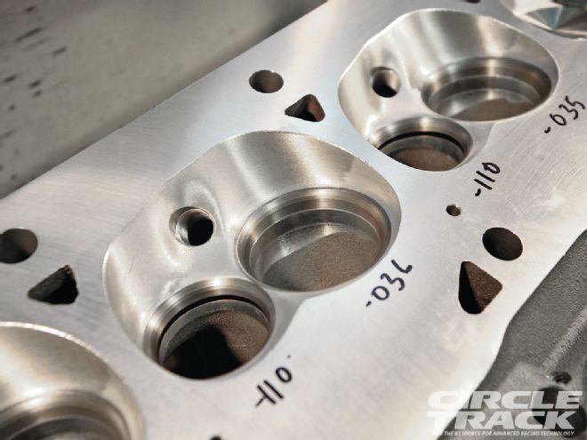
[4] Troutman marks the reading he gets next to each valve seat. The actual height isn’t important, it’s the variation from valve to valve that matters here. Ideally, all the intakes would be within a thousandth of an inch or less, and the same would go for the exhausts. If one valve is sunk lower than the rest, Troutman says there really isn’t much that can be done short of installing a new seat insert. But if a valve is too tall (sticks into the combustion chamber) more than the rest the seat can often be cut a little deeper to even things out. This is important because a valve that’s too high will serve to make the combustion chamber smaller, and if you are pushing the limits of minimum chamber size it can make your engine illegal.
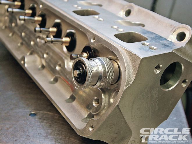
[5] Now that Troutman knows how the valves stack up on the combustion chamber side, he flips the head and measures the valve stem height.
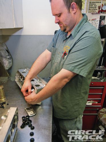
[6] Before measuring the valve stem height, the spring seats must be in place, but you don’t want any shims underneath.
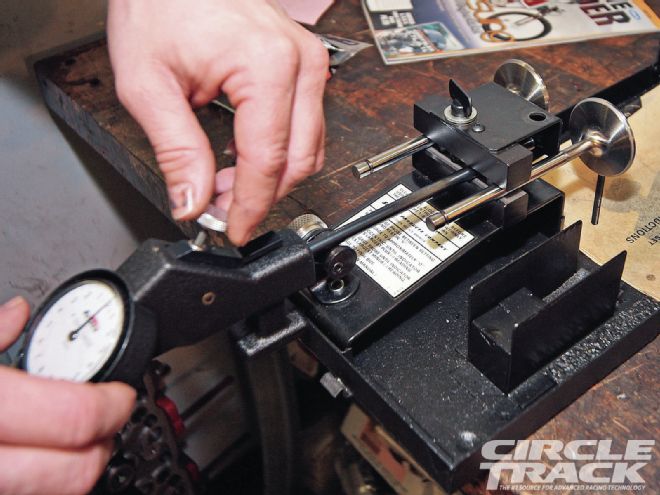
[7] A valve stem height gauge is a simple tool that makes accurate measurements a snap. You must make sure you are using the same retainers and locks that you will be using in the final build in order for your measurements to be accurate.
[8] Like on the chamber side, Troutman records the height of each valve, this time from the lock to the spring seat. Now, because he knows how deep the valve is sitting in the chamber, he can determine if any variances are because of the valve seat height or because of the height of the spring seat and can cut the seats accordingly.
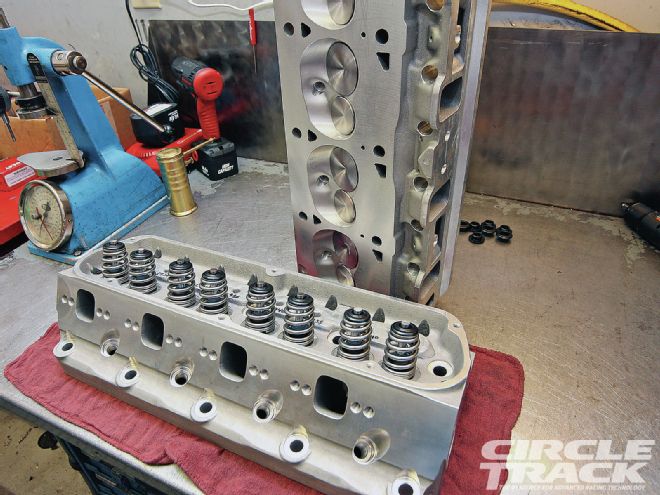
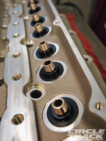
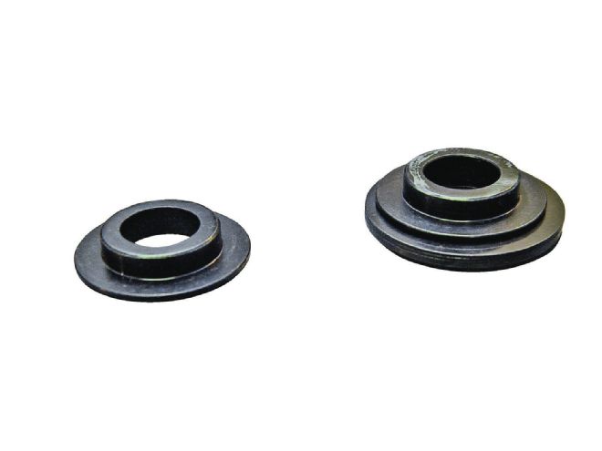
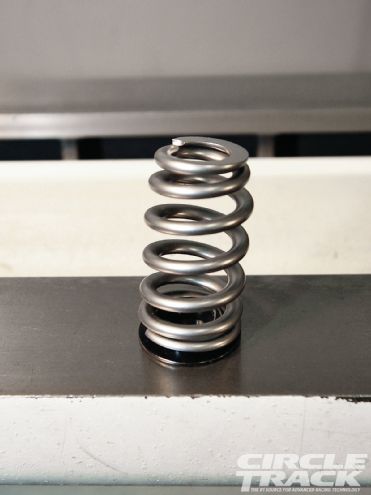
[9] The point of all this is to be able to minimize or eliminate the use of any shims underneath the spring seats (right). Shims are a band-aid that serve only to help achieve the correct valvespring installed height. The problem is that shims create a couple of compromises that can harm the valvetrain. First, stacking shims weakens the foundation that the valvesprings sit on. It allows more spring “wobble” which hurts the spring’s ability to maintain proper valve motion at high rpm levels. Second, shims serve as a heat insulator. One of the biggest enemies to spring life is heat, which is generated every time the spring is compressed. Besides oil splashing the spring, the only other way to remove heat from the spring is through the head to be carried away by the coolant flowing through the water jacket. Shims help hold that heat against the spring. And finally, cutting shims can often mean using a shorter valve stem, which cuts overall weight and also helps stabilize the valvetrain.
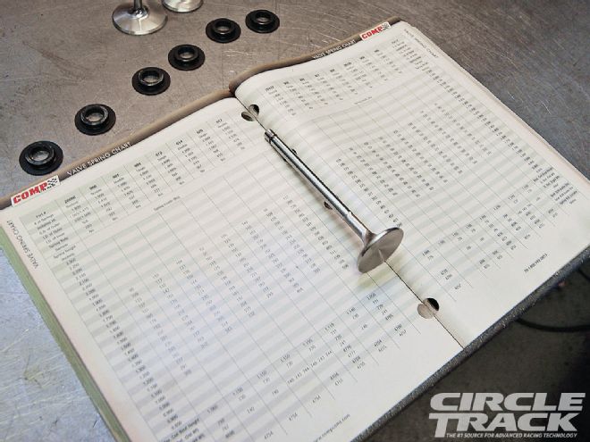
[10] Notice that we haven’t talked about valvesprings yet. That’s because Troutman says the valvesprings shouldn’t be chosen ahead of time and the valvetrain made to fit them. Instead, all works together. Many spring manufacturers publish the specs of all their valvesprings in their catalogs, as Comp Cams has done here. Now that he knows the valve stem height, Troutman can choose the spring that has the correct rate to create the correct seat pressure at the spring’s installed height along with the optimum open pressure. Troutman says Comp offers enough springs that he almost always can find the right spring to meet the needs of the engine and almost never has to resort to shims to make the installed height fits the spring’s requirements.
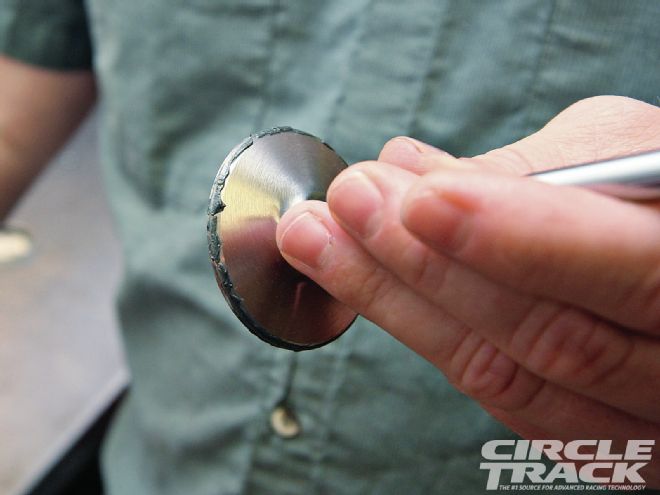
[11] You should also check and make sure that the spring seat you are using also works as a locator. If it is right, the spring will be a snug fit over the locator on the spring seat. The picture shows how the fit is snug enough to hold the edge of the spring up on its own.
[12] Entire articles can be written on seat angles alone, and we won’t touch on them much here. But before beginning final assembly, Troutman laps the valves. The first step is to apply a small amount of lapping compound to the valves around the seat area.
[13] Troutman spins the valve in its seat. The slight abrasiveness of the lapping compound helps provide a better seal by smoothing away any tool marks left by the cutter while it also shows the area where the valve meets the seat.
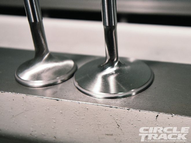
[14] After the valves have been lapped, you can see exactly where the valve contacts the seat in the combustion chamber. Notice it is approximately in the center of the seat face. Some engine builders try to gain a little extra flow by moving the seat area to the extreme edge of the valve. But this means that when it comes time for the rebuild, recutting the seat will drop the valve into the port, which will hurt performance. So to help maintain peak performance over the course of a season—or even longer—you must plan ahead.
[15] Besides sealing the combustion chamber, the area where the valve contacts the seat is also the primary way heat moves from the valve into the head where it can be swept away by the coolant flowing through the jackets. The seat area should be at least 0.040-inch wide for the intakes and 0.060 for the exhausts(they will grow slightly as the engine is run). But be careful that the mating area isn't too wide. Besides hurting flow, a seat area that's too wide will spread the loading provided by the spring over a larger area. Troutman says he's seen occasions where a seat that's too wide will allow a piece of carbon or trash to damage the seat, while a narrower seating area will create enough pressure between the valve and the seat to break up any carbon before any damage occurs.
[16] Finally, a note about valve guide clearance. With an 11/32-inch diameter valve stem, a good rule of thumb for the valve guide clearance is to be between 0.0015- and 0.002-inch. If you are running cast-iron guides, go for the larger end of the range at 0.002 to avoid galling or sticking. With bronze valve guide inserts you can go for the tighter side. Generally, you don’t want any more than 0.002 clearance because that will allow the valve extra movement in the guide which will beat up the seat.
[17] To avoid valve stems galling in the guides from the extra heat, some valve manufacturers will actually make the exhaust valve stems a few tenths of a thousandth undersized. Because of this your machinist should always set up his measurement tools and measure all the intake guides, then recalibrate and go through the exhausts separately.