Many of us have Chevy 350 engines installed in our trucks that produce relatively good power. The 350 is a great replacement/transplant for the stock straight-six and for some of the earlier V-8s. Look around and you can find a 350 in every junkyard, some worse off than others, but my point is that they are everywhere.
From the '60s on up to the late '90s, 350 Chevy engines were produced to go in cars and trucks by the hundreds of thousands, not to mention the many crate engines that were built. So I ask the question, does your small-block feel like it could use some more power? Are you wanting some added ponies under the hood, but don't want to go through the trouble of pulling the engine and/or messing with the bottom end?
How about bolting on some new parts like a distributor, heads, cam, lifters, and tune your carb to make that V-8 sound like a V-8? It's not that hard of a job; just a little intimidating at first glance. The hardest part is making sure all the parts jive with each other. That's where companies like Summit Racing come in with their great website and tech support.
Depending on what internals, cylinder heads, intake, exhaust, camshaft, and carb your 350 has really determines how much power it will or can make. Let's be honest with ourselves, do we need an 800hp small-block? Yeah that would be cool, but to answer that question, 800 hp has its place in something, but for the most part a mild street driver is anywhere from 290-600 hp.
If you start getting into the 600-plus area, then you start looking at blowers and turbos with a big price tag. This is when you have to ask yourself what you will be doing with the truck. Will you be driving on the street 100 percent of the time? Or will you want to drag race or autocross? Generally we build our trucks to have good times with, to be reliable when we are out on the road, doing a burnout or two, and getting on the gas when we merge on the freeway. To do all that, you don't need a big-horsepower dyno number when a mild 350 will get the job done.
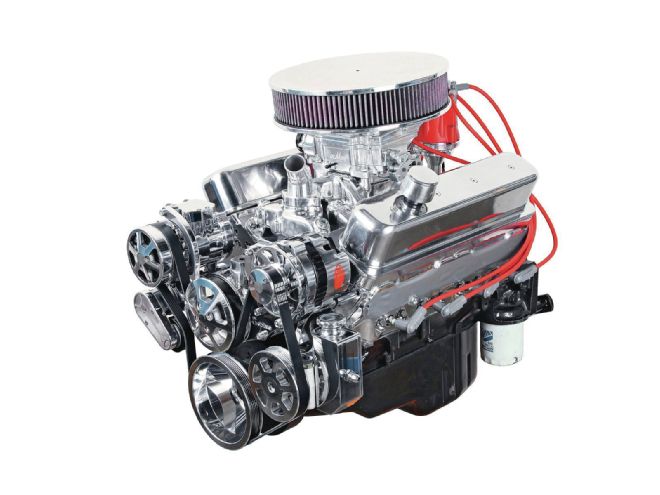
Let's talk about the engine we are going to test for you guys. It started off as a replacement Chevy ZZ4 crate engine that was rated at 330 hp at the flywheel, but we would like to bump that horsepower rating with some bolt-on parts. The stock heads that came on our small-block are referred to as 906 heads; they have 170 runners with 64cc combustion chambers and perform well, but leave room for huge improvements.
We called Summit Racing and told them what we wanted to do and they recommended using a set of Trick Flow 195cc intake and 62cc combustion chamber heads. The heads we ordered came cast and we decided to have the engine parts polished including the heads. For the cam parts we called Comp Cams' tech line and they suggested a cam and lifter combo for our application below. The engine went together well. Check out how we made 417 hp with bolt-on parts.
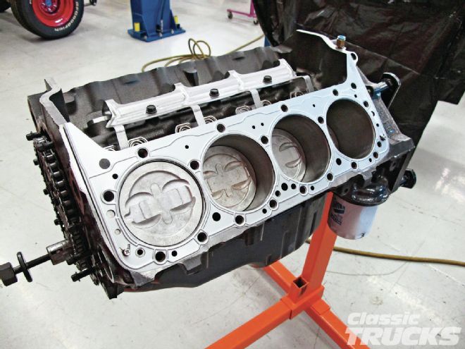 01. Starting off with ordering cylinder heads, you need to either find out what the combustion chamber size of the old head is or figure out what piston you have in the small-block. Most Chevy-style pistons can be identified through one of the many Chevy engine-building books or looking it up online. These particular pistons (part number 12361371) have -12cc dish and were 0.030 below the deck of the block.
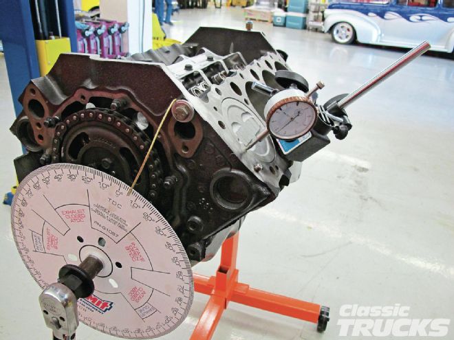 02. Since the engine was apart I took the opportunity to find out where top dead center (TDC) of the piston is; this way I could pull the cam out and install it at TDC. Shown is a Summit Racing degree wheel that I used to find out how far down the piston was in the hole at (TDC). It is important to see how far the piston is in the hole because it can be too high and hitting the valves or too low and lose compression. This also helps make sure the crank balancer has not spun.
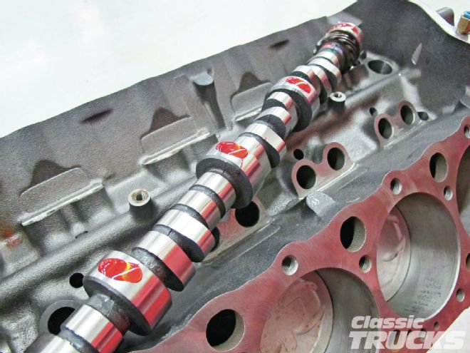
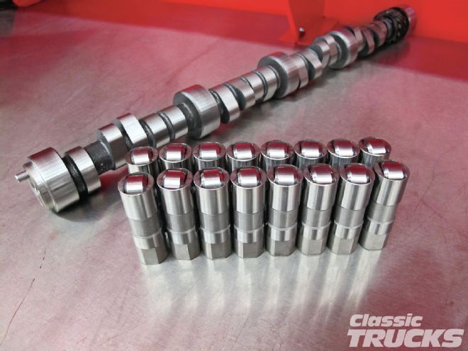 03. To hop up our 330hp test engine I used a Comp Cams hydraulic roller camshaft (part number 08-423-8) with new Comp Cams hydraulic roller lifters. The cam specs out at 224 intake and 230 exhaust at .050 of lift. Comp advertises that this cam has a great powerband at 1,900-5,600 rpm and that is just perfect for our mild street engine.
 04. I started the build by removing the cast-iron heads, intake, balancer, and timing cover. This way I would have access to the lifters, camshaft, and timing set. This small-block is what they call a Gen II hydraulic roller cam. It has guide plates for the hydraulic lifters, so that the roller part does not spin in its bore.
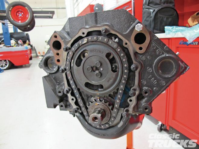 05. With the timing cover removed, the three bolts holding the camshaft can be removed. Notice the cam alignment pin is facing toward the No. 1 cylinder and the timing set dots are pointing toward each other. This is TDC on No. 1 cylinder.
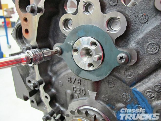 06. After sliding off the cam gear and chain, the cam trust plate was removed. On Gen II Chevy 350s this plate replaces the cam thrust button and keeps the cam from wanting to come out of the engine under load.
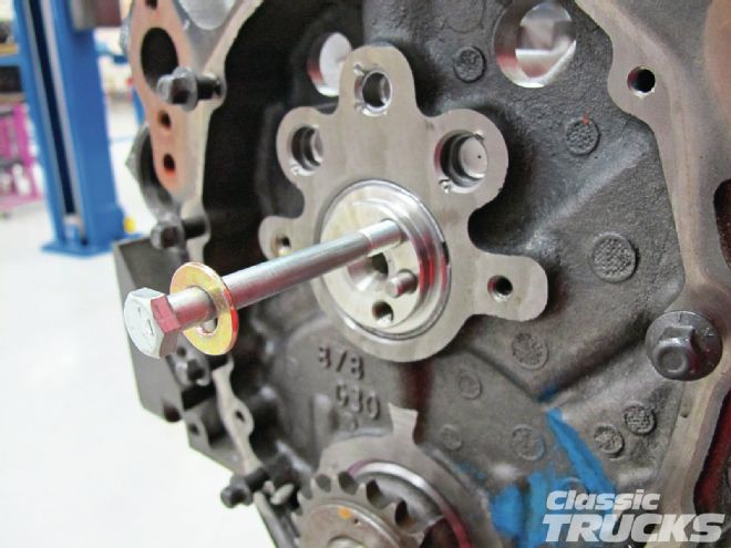 07. Using a long bolt, the cam was removed from the engine. Carefully remove the cam as you can scratch the cam bearing inside the engine if you force it out.
 08. I used assembly lube on the cam to help protect the cam and cam bearings during initial startup. A coat of assembly lube on the cam lobes will also help if you are not going to degree the cam. The thick assembly lube can give you false readings on the dial indicator when degreeing the cam. It is recommended that when done degreeing the cam that assembly lube is placed on the lifters and cam lobes before starting the engine.
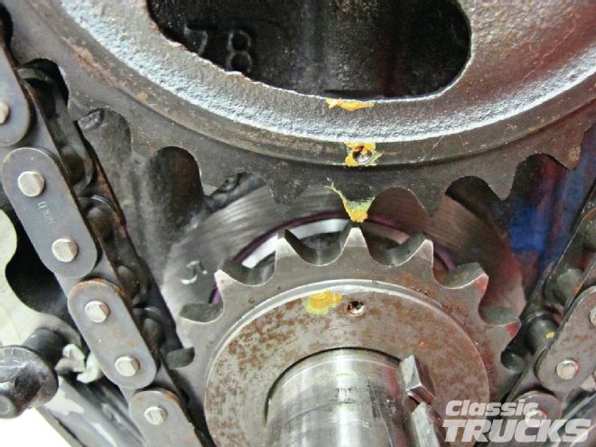 09. With the cam installed, make sure that the alignment pin is pointing toward the No. 1 cylinder and both the dots are pointing toward each other. Another indication that the timing is correct is to look at the crankshaft keyway. The keyway should also point to No. 1 cylinder. I ordered a new double roller timing set from Comp Cams (part number 3136), but forgot to get a larger timing cover from Comp. The double roller chain will hold up longer without stretching versus the stock chain.
 10. Since we set our camshaft at factory
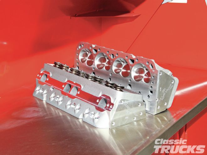 11. I used a set of aluminum Trick Flow heads (part number TFS-30400006) that helped increase the horsepower numbers and reduce the total engine weight. I ordered the Trick Flow heads from Summit Racing along with most of the other engine parts. The heads are 195cc intake runners with 62cc combustion chambers. Since we looked up the piston dish, around (-12cc) and the depth of the piston in the bore when at TDC (-0.032), I was then able to calculate what the compression ratio was roughly going to be by entering the numbers in a compression calculator I found online. I calculated the compression right at 9.6:1 with a 62cc head and a 0.015 Fel-Pro head gasket.
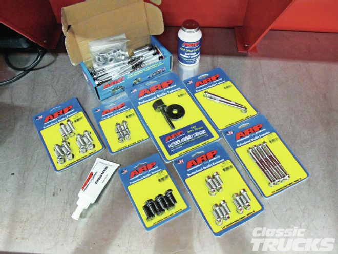 12. With the head degreased and the block cleaned up I placed the head gasket on the engine. New ARP polished six-point bolts were ordered to not only clean the engine up a little, but more importantly to hold the bolt-on parts in place.
 13. The bolts' threads were then covered with ARP Ultra Torque lube to help with torqueing the heads down. I also put a dab of Ultra Torque lube on the bottom of the bolt head and washer so that they would slide off one another and not cause a false bolt torque reading.
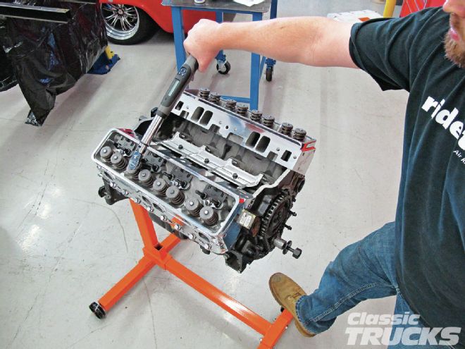 14. The heads were tightened down in stages of 50 lb-ft, 60 lb-ft, to the final torque of 70 lb-ft. I also printed a head bolt tightening sequence photo that I found online. This way I couldn't forget what bolt was next.
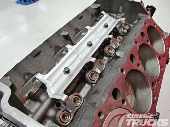
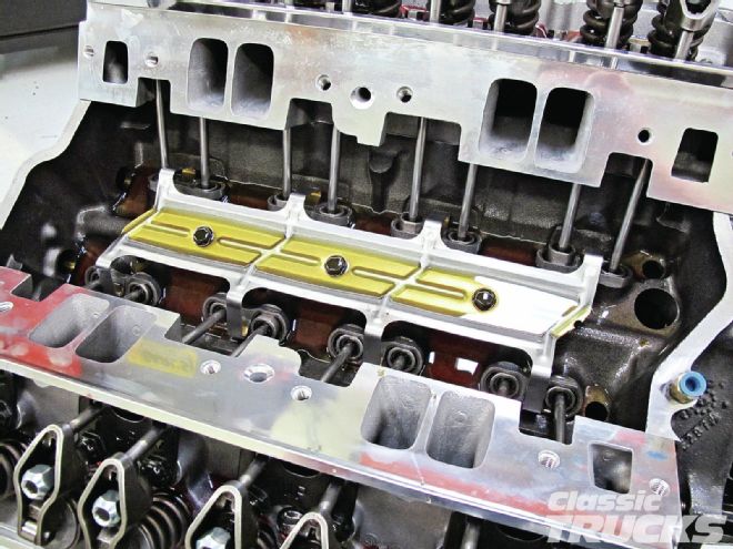
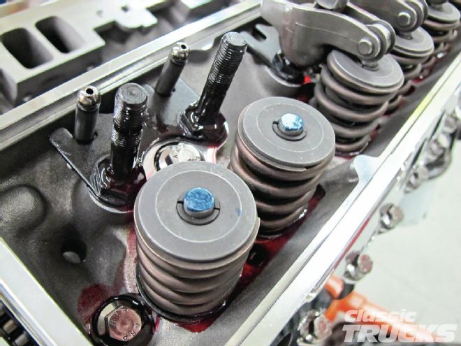 15. Next I mounted the studs that hold the rockers and guide plate for the pushrods. Make sure to install a set of pushrods in the guides before torqueing down the studs. This way you can make sure the pushrods are not binding on the guides.
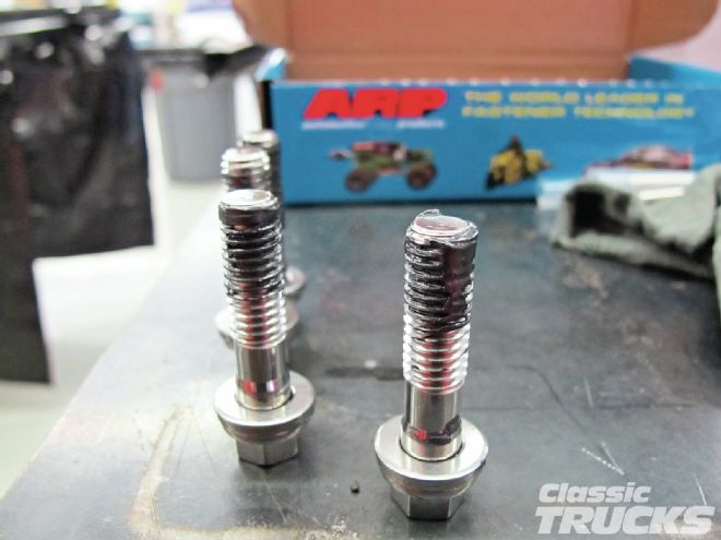
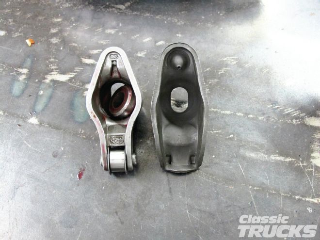 16. Our test engine got an upgraded Comp Cams rocker arm that has a roller tip in the end. Notice the difference between the stock rocker on the right and the Comp Cams rocker on the left. The Comp Cams rocker looks similar, but the roller tip frees up wasted energy caused by friction on stock stamped rocker arms.
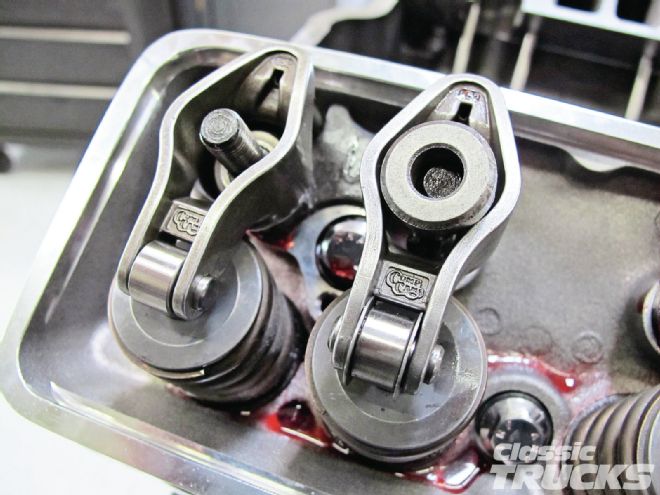 17. On the left is a Comp Cams rocker that has no guide plates on the rollers. The right one has guild plates. I ended up using the roller-tip rockers that had no guilds, since the lifters already had guilds and I felt they were not necessary in this application.
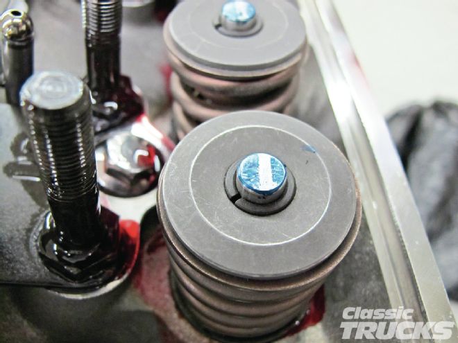 18. Using a permanent marker or dye, I marked the top of the valve and installed the intake and exhaust push rods on one cylinder. Notice the top of the valve has the paint removed from the center and toward the right side of the valve tip. When I hand spun the engine over with the pushrod and rocker installed, the top of the rocker took off the paint where it was moving. This indicates that the top of the rocker is not centered on the top of the valve. I used a Comp Cams adjustable pushrod (part number 7905-1) and repeated the steps. The correct pushrod length was determined to be (part number 7809-16) 7.266 inches long.
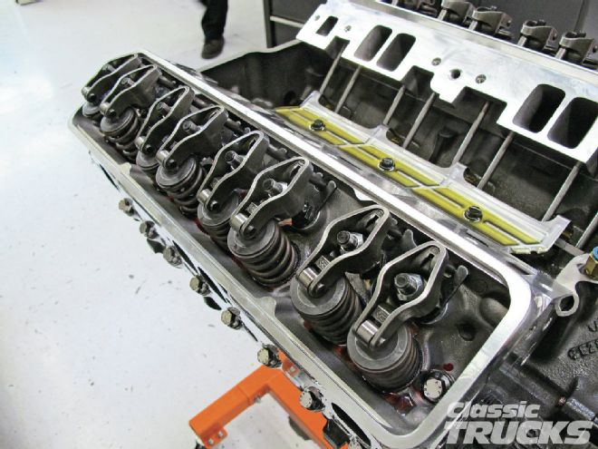 19. I waited a few days for the Comp Cams pushrods to show up and now the rockers were checked one more time to make sure I got the pushrod length correct. Now adjusting rockers is no big deal and in fact it is easy as making sure that both valves are closed and then tighten the rocker nut until the pushrod is at zero lash. Zero lash means that the pushrod will no longer move up and down, but will spin free when twisting. Then rotate the ratchet to 12 o'clock and tighten it to 6 o'clock. This puts a preload on the lifter, but not enough to hold the valve open at high rpm. Repeat these steps on the rest of the rockers by rotating the crankshaft and positioning the valves so they are closed and not opening or closing.
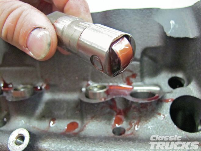
 20. Comp Cams engine break-in oil was then added to the lifter valley so that I could prime the engine using a Summit Racing oil pump priming tool. This way, when the engine is started, the new lifters would be primed and the crankshaft, cam, rockers, pushrods, and other moving items would be protected with oil.
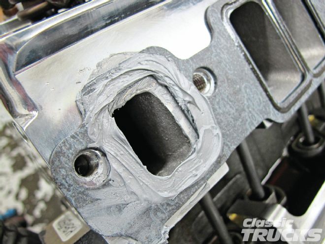 21. The intake was ready to be bolted on, but before that I took some extra time to properly seal the intake gaskets. I really like using gray silicone on anything with oil, water, or fuel to help seal gaskets. I ran a small layer of gray silicone on the underside and top side of the intake gasket water passage. A 3⁄8 bead of gray silicone was also used to seal the lifter valley to the intake manifold.
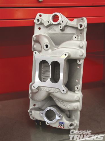 22. An Edelbrock 7501 Performer RPM Air-Gap was used to help promote great airflow inside the intake and make great usable power from 1,500-6,500 rpm. I ordered the satin finish because we were going to paint the engine gloss black, but decided to go with the polished look instead.
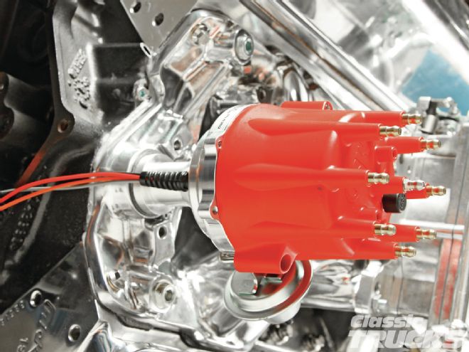 23. An MSD Pro Billet distributor was added to the engine to ensure we had plenty of spark at all times. The only drawback to the Pro Billet distributor is that you have the extra expense of an MSD controller, but have the advantage of dual spark. If you don't need or want an MSD ignition controller, then you could use an MSD ready-to-run distributor, which installs similar to GM's HEI units.
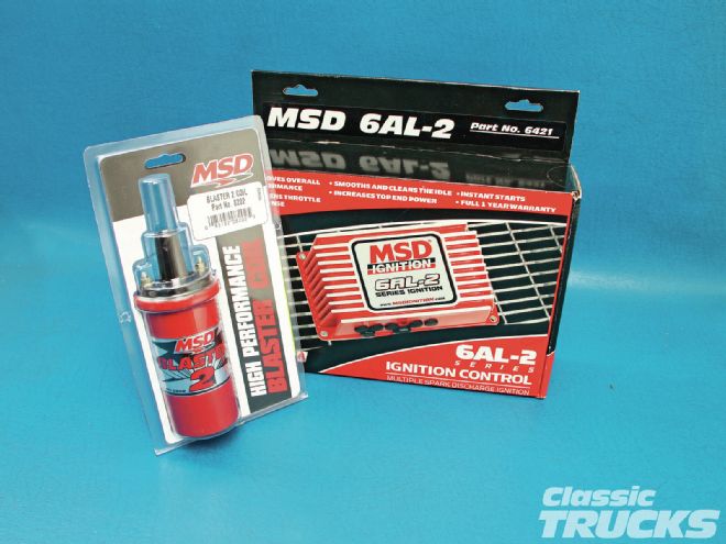 24. I used an MSD 6AL-2 ignition controller with a MSD Blaster 2 coil to control the spark. I've heard positive stories about this setup helping out with low-rpm idle quality and getting full spark at high rpm.
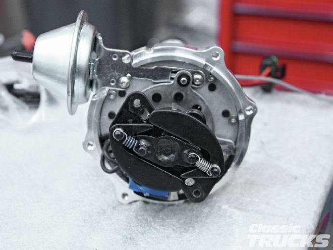 25. The MSD distributor came stock with the big springs installed on the mechanical advance. Those heavy springs might be too big for our application and we want the timing to go from initial to full (total timing) a little faster. Example: Total timing is measured by revving the engine to 2,500-3,500 rpm or wherever the timing stops advancing and checking the timing at full advance. In this case we wanted 35 degrees total timing. Now by reducing the spring sizes on the mechanical advance we can speed up the time it takes for the mechanical advance weights to go to full advance or total timing at 35 degrees.
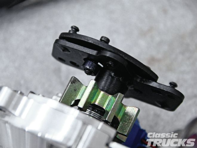 26. Now I hope you followed me on the total timing because this is where it may get a little confusing to some people. On the underside of the MSD distributor there is a small, black bushing. This bushing can be swapped to a different size to switch the amount of advance that the mechanical advance can travel. Example: Installing a bigger black bushing will limit the amount of mechanical advance travel to 18 degrees total advance from initial timing. You can look at it like this, if we set the total mechanical advance to 35 degrees we could play with the amount of travel from initial timing with bushings. For instance, 35 degrees total equals 17 initial with black bushing, 35 degrees total equals 14 initial with blue bushing, 35 degrees total equals 10 initial with silver bushing, and 35 degrees total equals 7 initial with red bushing. Initial timing is the timing while the engine is idling.
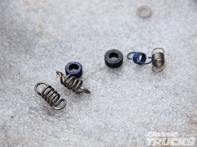 27. Overall weight of the vehicle can affect how fast timing can come on. For example, the lighter the springs, the faster the timing goes from initial to total timing. Too light of a spring on a heavy truck can ramp the timing up too quick and cause a pinging noise or what is know as detonation. In this case, switching one light spring for a slightly heavier spring might solve the detonation by allowing the rpm to be higher before the mechanical advance reaches total timing.
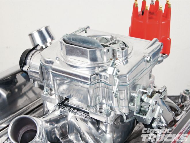
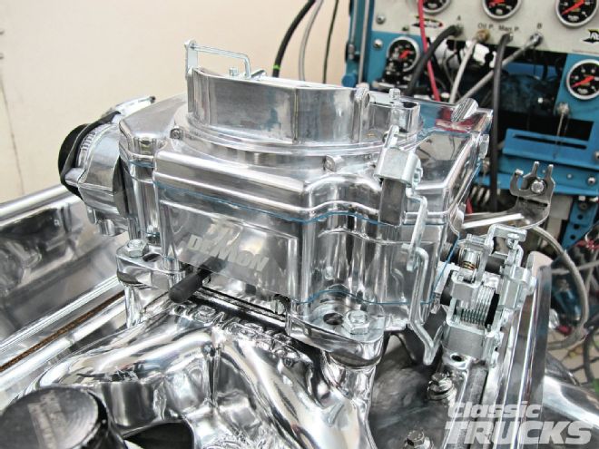 28. I used a Demon 625-cfm Street Demon carb on top of our test engine. I've got to say that I was not intimidated by this carb at all because it was very easy to change jets to lean or richen the mixture. Not to brag, but I was able to change the secondary jets in eight minutes while the carb was on the bench.
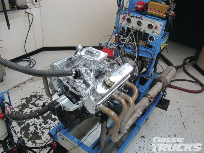 29. We warmed the engine up and ran the engine through a preprogramed break in procedure because of the new lifters and cam, etc. We set the timing to 35 degrees total and also set the idle speed at 750-800. Demon recommends 5-6 psi of fuel pressure for the Street Demon carb. We lightly accelerated to simulate a cruise condition 2,500-3,000 rpm and the air/fuel ratio was around 14.0; that's great for light throttle cruise conditions. After the engine warmed up, idle was adjusted again and we were ready for a full dyno pull.
 30. To change the secondary jets the carb has to be removed from the engine.
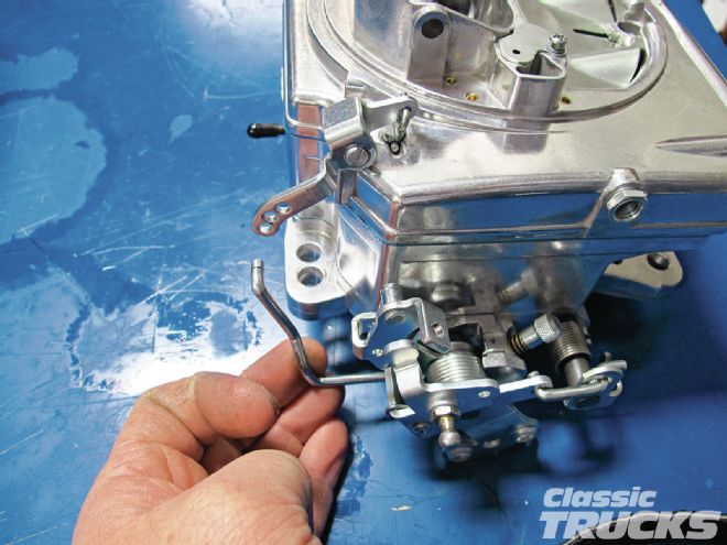
 31. Start by removing the accelerator linkage and choke linkage.
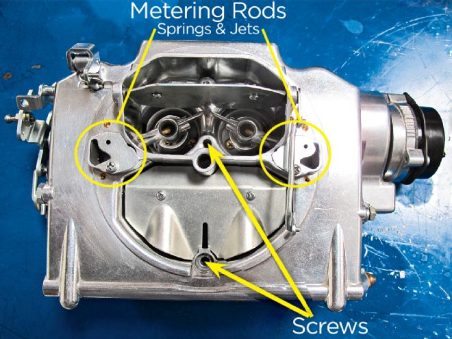 32. Then remove the two bolts on top of the carb here and then flip the carb over. Fuel will come out so make sure you have a catch can or a large stainless bowl to catch the fuel. Six bolts hold the rest of the carb together from the bottom. Then the carb should split apart, but do not pry on any surface of the carb. If the carb sticks together then you can use a small soft rubber hammer or the plastic handle end of a screwdriver to gently tap the exterior of the carb. Note: make sure you have all the bolts out before taping on the carb. Metering rods and springs can be adjusted from the top of the carb to help tune the primary side.
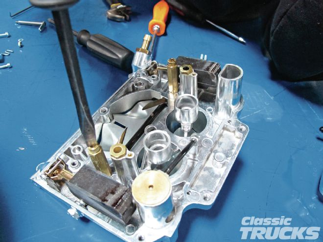 33. The top of the carb will separate from the base and look like this. A large screwdriver is used to remove the secondary jets. Because the engine was running slightly lean at wide-open throttle 13.5-14 air/fuel ratio, we wanted to give the engine more fuel when accelerating. We went from an 80 secondary jet to an 82 secondary jet and retested the engine. Turned out by changing the secondary jets we were able to add more fuel while at wide-open throttle and drop the air/fuel ratio to a richer and safer 12.5-13.
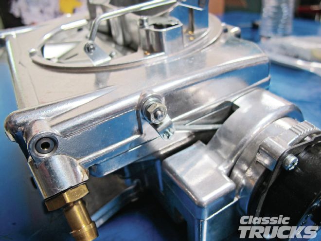
 34. Idle jets can be adjusted to lean or richen the mixture for better idle. A secondary air valve is used to blend the transition from primary to secondary. In other words it will fine-tune the fuel ratio between primary side (idle-cruise) to the secondary side (slightly off cruise to WOT). Idle adjuster can open and close the throttle blades to set the desired idle speed of the carb.
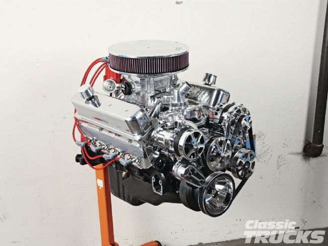 35. The last thing I did was install an Eddie Motorsports polished front-runner kit to finish off the sleek, shiny look. Now all I have to do is get out the polish and spend some time polishing this bad boy.