With the engine block for our 455-based stroker mule engine completely machined, Craig Wise of RaceKrafters will now work on the rotating assembly, which includes the crankshaft, connecting rods, pistons, rings, and rod bearings. Our mule will enjoy all new internal parts thanks to a stroker kit sourced from Butler Performance that consists of a forged 4340 Eagle crankshaft, Eagle connecting rods, Butler-designed Ross forged pistons, and Total Seal rings. Thus, many of the procedures that would be required to retain used parts do not apply, especially since the Butler Performance assembly comes balanced already.

Since many Pontiac hobbyists may choose to refurbish the stock parts during a rebuild, this article covers the procedures in-depth that would apply to a new or used rotating assembly. This way the readers can have a full understanding of what is required to properly prepare a rotating assembly for a Pontiac engine. Also note that for a proper engine build, the new parts need to be checked and reworked for the exact application. You cannot just take an engine part out of the box and slap it in place.
So, is it better to buy new or retain an original Pontiac part? If your engine is all-original, the crankshaft and rods are in good shape, and you’re doing a stock or mildly modified build, you can have the machinist perform the proper tasks for them to remain in service. The sticking point often is that the labor charges come very close to the cost of a new, mass-produced connecting rod or crankshaft. But keep in mind that the new parts will require some expense to become ready to install. For example, a new or used crankshaft will need to be balanced.
The greatest price disparity will be found with the connecting rod choices. You can rework the old rods and retain the press-fit wristpin (stock replacement cast pistons and the TRW/SpeedPro replacements are not cut for floating pin-locks). The upside is that your engine will still have original Pontiac parts. Talk it over with the machine shop and have it provide a ballpark price once it confirms your parts are usable. If, however, you plan to make substantially more power and use floating wrist pins with high-performance forged pistons, forged rods are usually a better investment.
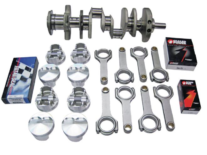 1 Here’s a rotating assembly from Butler Performance to build a stroked 455. It features a 4.250-inch-stroke, Eagle 4340 forged steel crank with 3.25-inch mains, Eagle H-Beam 6.800-inch forged rods, forged Ross lightweight pistons (4.155, 4.181, or 4.211 bore size), 0.990 Ferrea forged and tapered pins, file-to-fit rings, rod and main bearings, and was internally balanced. The price is $2,049. We’ll get into a deeper description of the individual parts in the upcoming assembly article.
The following steps are what is required for a proper rotating assembly to be installed in your engine.
Crankshaft
One of the first places the machine shop will inspect on a used crankshaft is the keyway that holds the harmonic damper. If the damper bolt was not torqued properly, the crankshaft sprocket will be driven by the key instead of the bolt friction. In addition, if the flat washer under the damper bolt is distorted or dished, it should not be reused.
 2 After a careful visual inspection, the piston dimensions are confirmed. The diameter is measured at the skirt with a micrometer.
The machinist will visually inspect the snout threads for damage. If any exists, a determination will need to be made if a repair can be accomplished by chasing the threads or installing a thread repair insert kit. The flywheel flange bolt holes will be checked. The crankshaft will be cleaned, and the threads chased or a repair kit will be required, and the rear main oil seal surface will be examined for wear. Wear sleeves are made for most if not all Pontiac engines.
After the visual inspection, the crankshaft main bearing journals and crank pins will be measured with a micrometer. The crank pins are the area that attaches to the connecting rods. If all looks good, the crankshaft may then be mounted in vee blocks to check for bend, snout trueness, and flywheel/flexplate flange runout.
When examining a crankshaft, the shop will also check for anything that looks abnormal. Any nicks, dents, or pits in the journal outer diameter must not exceed 0.005-inch or have raised metal. Any journal outer diameter score marks must be at least 0.125-inch from the fillet tangent point, a maximum of .010-inch wide, and circumferential, not axial.
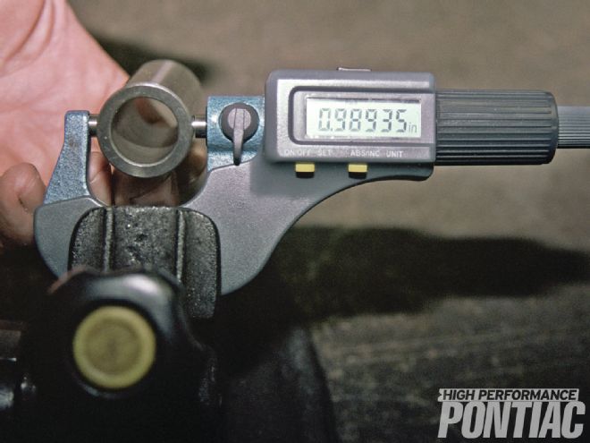 3 The wristpin dimension is recorded and will be used for small end clearance and piston pin-bore sizing.
Many do not realize that in a running engine, the crankshaft is constantly bending and flexing as the cylinder gas load is applied and the direction of the pistons change. Over many years of use and miles, it’s possible that the crankshaft will develop minute cracks or fissures that will eventually lead to failure. This is especially true with Pontiac engines, since many of the engine parts we are using can be 40 or more years old.
 4 An experienced machinist will be very comfortable with a dial bore gauge. Before taking any measurement, the bore gauge needs to be set up in a special fixture.
Keep in mind that as the horsepower of an engine is increased, the cylinder pressure goes up in lock-step. Also, more rpm results in more load on the crank. A crankshaft that functioned fine with small cracks in a 250hp engine will fail almost immediately in a 500hp application. For this reason, the crankshaft should be Magnaflux-inspected for any problem areas.
The cleaning procedure for a used crankshaft is not complex and is often nothing more than a good soaking in a parts bath, such as a Safety-Clean machine. A shop will then use an application-specific brush or an old-fashioned pipe cleaner to flush the oil holes in the journals.
Machine shops will measure the crankshaft using a micrometer. Each rod journal, along with all of the main journals, will be measured for taper, out-of-round, and undersize from wear or a previous rebuild. The micrometer is generally used to measure at defined locations on the journal. Rod journals will experience the most wear on the underside. The term flat crank is often used to refer to a crankpin that is out-of-round because of underside wear. An out-of-round or tapered condition of 0.001 inch or more requires the crankshaft to be reground.
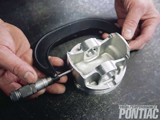
 5 When measuring a piston pin bore, the operator needs to have a gentle touch with the tool to take an accurate reading.
Occasionally the bearing journals will develop an hourglass or barrel-shape. The maximum limit for this condition is 0.001 inch for a production engine and almost zero for a performance application.
Most newer Pontiac engines use a combination of a grooved upper main bearing and a plain or non-grooved lower bearing. This can create the need for the journal to be reground. If the crankshaft journal has a ridge that exceeds 0.0003-inch, the journals will need to be reground to a standard dimension. If the ridges are not removed, it can stress a new set of bearings and cause them to fail shortly after the Pontiac is started and run for the first time.
Crankshaft alignment refers to its straightness. The recommended method is to use V-blocks and a dial indicator. Alignment from journal to journal should be within 0.001 inch. The overall deviation must not exceed 0.002 inch of variation. Runout of the crankshaft snout and flywheel face cannot exceed 0.001 inch.
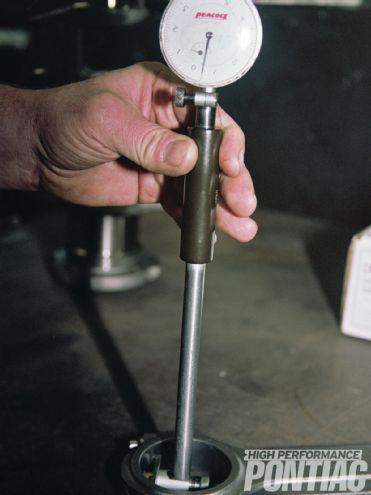 6 Craig used a dial bore gauge calibrated to the proper dimension to check the big end on every new connecting rod.
When machinists check for taper and out-of-round, they compare the micrometer readings they get with the specification size chart for the crankshaft to determine if it has been ground undersize already. The usual undersizes to which bearings journals are ground are 0.010, 0.020, or 0.030 inch. Bearings are commonly offered in these undersizes to fit reground crankshafts.
Most machine shops do not possess crankshaft-grinding equipment. This service is usually sublet to a specialty job shop that does nothing but crankshaft repairs and remanufacturing.
The process is accomplished with a grinding stone that is held to extreme accuracy. If the crankshaft journals are tapered, out-of-round, or have any imperfection, then it will need to be reground. It is customary to grind off the minimum amount of material to keep the crankshaft strong. If a crankshaft is referred to as “10 under on the rods,” that means it was ground 0.010-inch undersized. Once a crankshaft is ground, bearings that have an outer diameter increased the amount of material removed are required to take up the difference. A crankshaft that was ground 0.010-inch under would use a bearing that has an outside shell diameter of 0.010-inch greater (thicker) than stock. The inner diameter will remain the same.
There are two schools of thought on crankshaft regrinding. Some shops don’t bother to take any measurements and just cut the crankshaft 0.010 inch. I don’t believe this is a good practice, since this not only slightly weakens the crankshaft, but induces an additional thermal stress from the grinding process. In addition, if the engine ever experiences an oiling failure, there may not be enough material left to reuse the crankshaft because of the unnecessary cut. Don’t be afraid to use a cut crankshaft though. It’s a very acceptable procedure when necessary.
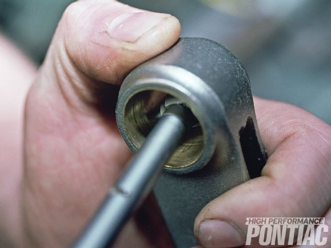 7 The tool needs to be reset to then confirm the small end size. The Eagle rod is bushed for a floating pin. The tip from the bore gauge rests gently on the bushing. Note the crosshatch finish on the pin bore.
Before a crankshaft is put back into service, it should always be micro-polished whether it was ground or not. All journals, filet radii, and seal surfaces should be polished to a 15 micro-inch finish.
Most Pontiac crankshafts have a knurl on the journal for the rear main seal, since it originally was a rope design. Many engine builders like to polish this off for use with a neoprene seal. However, once the knurling is removed, the engine must always retain this type of rear main seal.
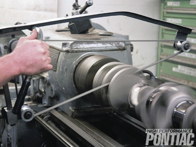
The crankshaft is spun in a machine and rotated in the same direction it operates, while a polishing belt that resembles emery cloth is held against the journals operated by an electric motor. The polishing cloth needs to pull the material away from rotation. Polishing is done to prepare the journal surface for proper contact with the bearing material, and also so the oil will be able to work properly and form the necessary oil wedge that separates the bearings from the journals.
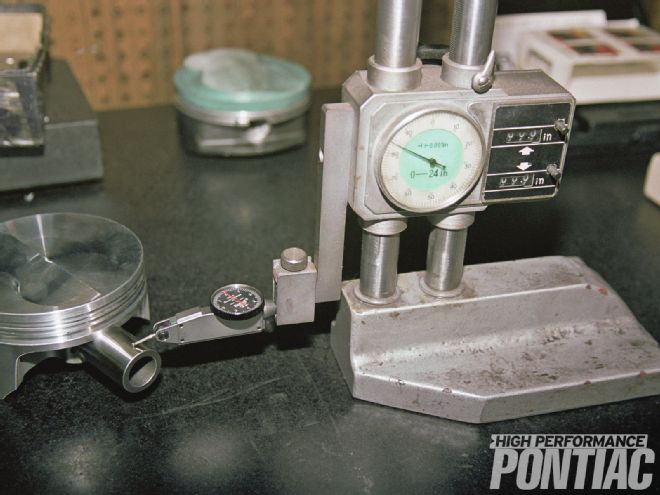
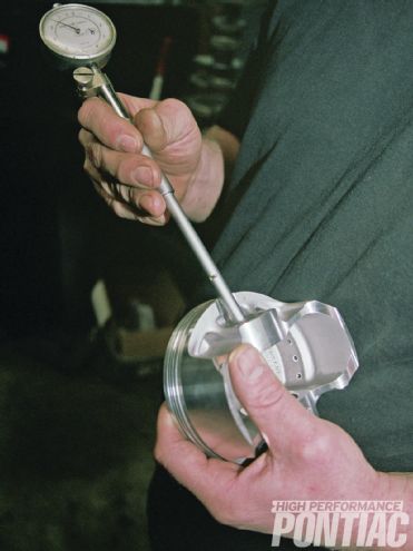
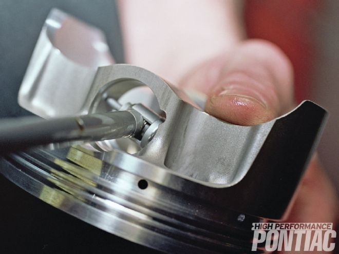
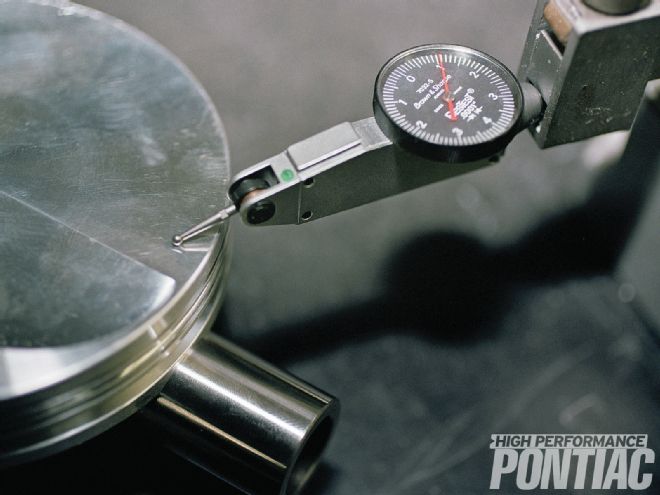 8 A special fixture is required to confirm the pin location (compression height) of the piston. Craig checks every piston to make sure there is no variation in manufacturing. There wasn’t.
Connecting Rods
A connecting rod is one of the most abused and least respected parts. Most enthusiasts don’t realize the load and stress that it experiences. For example, the connecting rod must support four to five tons of pressure during combustion. Also, the rod is required to reverse its travel many times per second. This load and stress, when combined with engine heat and cooling cycles, will eventually deform the end of the rod that attaches to the crankshaft.
The connecting rod consists of the rod itself and the cap that embraces the crankpin journal of the crankshaft. Where it attaches to the piston is called the small end; where it attaches to the crankshaft is the big end.
Connecting rods are checked for stretch and concentricity of the big end. Since a loss in concentricity or elongation is greatest in the vertical direction, the two are impacted simultaneously. To measure the big end of the connecting rod, several methods can be used:
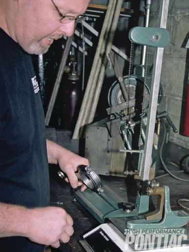 9 A rod holding fixture is used to weigh each end of the connecting rod to determine the mass separately.
Specific bore gauge—This tool has two rigid and one floating pin on the rear of the gauge. The floating pin is adjusted to fit the rod being tested. When the gauge is properly adjusted to fit the rod bore, the machinist rotates the gauge around the bore. The dial reveals out-of-roundness in thousandths of an inch.
Conventional dial bore gauge— Using this tool, the rod is measured in both directions. The difference in readings reveals the elongation.
Inside micrometer or telescoping gauge—A series of measurements are taken across the bore to determine the size and roundness. If the connecting rod big end is elongated, it will cause the rod bearing insert assembly to be out-of-round when installed, and lead to premature engine failure and spun bearings.
A common mistake that many shops and enthusiasts make is not reconditioning the connecting rods. The piston needs to be removed from the small end for this. Depending on the wristpin design—either pressed or floating—this procedure varies. To remove a floating pin, the connecting rod small end will have some style of locking clip that needs to be removed. Once the lock is taken out, the pin will slide out of both the piston and the rod.
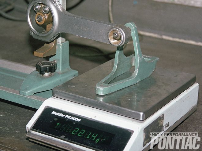 10 The big end is weighed first. The rod is then turned around and the small end mass, which would be considered a reciprocating member, is recorded, as shown here.
Most Pontiac engines had pressed fit pins from the factory. These are an interference fit. Many shops simply place the piston in a special vice and, using a hydraulic press with the proper arbor, press the pin out. Some may heat the piston pin bore with a small torch and then press the pin out in the same fashion. To install the pin, the small end of the rod is usually heated in a connecting rod furnace to expand the bore. Then, very quickly, the pin is slid in before any contraction from cooling occurs. An experienced machinist will perform this procedure without “bluing” the rod from excessive heat. Extreme temperature during heating will stress the rod and may induce premature failure or distortion of the pin bore.
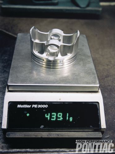 11 Each piston is weighed and, as with the rods, correction is made to the lightest test value in grams. Each set of rod bearings, piston pin locks, and piston rings is weighed as well and added to the calculation.
After the piston is removed, the rod will be measured (big end) to determine if it needs resizing. During a major rebuild, it’s usually necessary to resize the rods to perform a high-quality job. This process is done by cutting both the cap and end of the rod that the cap attaches to using a special rod-cutting machine. Once it’s determined that the surfaces have been cut enough to remove any elongation, the rod needs to be honed on an application-specific machine to achieve the proper inside diameter for the bearing and crankpin journal.
Before the rod can be cut, its bolts or studs are forced out using a hydraulic press. Prior to the honing process, new rod bolts or studs need to be installed. This is done in the same manner as the removal, with a hydraulic press. When the big end of the rod is honed, it not only restores the proper inner diameter, but creates the proper surface for the bearing shell to reside against.
The small end of the rod usually requires little service other than measuring for the proper interference fit with the wristpin for pressed application. If the end is distorted, it may require a hone and wristpin adjustment through machining or purchasing a different size.
 12 Once everything is weighed, the total mass is found. There is also a calculation for the weight of standard engine oil that is used by the industry.
When the connecting rod is reassembled, a rod vise will be used to hold the rods and make sure the cap aligns properly with the main body. Also, the rod will be torqued to specification while in the rod vise, and the amount of bolt stretch will be measured. Connecting rod bolts take most of the brunt of the load in the engine and must be an exact length to work properly without failure.
Pistons
New pistons will be examined and measured at the bottom of the skirts. This can be done with a very large micrometer or a caliper. The pin bores will be examined and measured with either a snap gauge or an inside micrometer.
Other measurements will be taken, such as confirmation of the compression height of the piston. This is determined by the wristpin location in the piston. A special fixture is required to accurately determine this value.
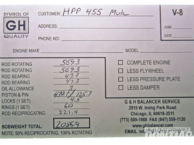 13 The next step is to make up a bobweight card so the proper mass is attached to the crankshaft for balancing.
Before new pistons are installed, the machinist will go through the measuring procedure and inspection to catch any flaws. In addition, any high spots on the crown (top) will be removed to avoid a hot spot, which can induce detonation.
Engine Balance
At times, there is some confusion in the hobby about whether the factory rotating assembly was internally or externally balanced. This is important since the Butler stroker kit is internally balanced.
It is generally accepted that 326-455 engines were internally balanced and 301s were externally balanced. However, on 326-455 engines, the factory crankshaft was balanced but the flywheel/flexplate was also drilled on one side for fine balancing. This is confusing, since a general rule is that if there is balancing done on an external rotating member (flexplate/flywheel or harmonic damper) the engine is considered to be externally balanced. But since there was correction made to the crankshaft mass at the factory, the engine could be considered internally balanced to an externally balanced flywheel for fine correction.
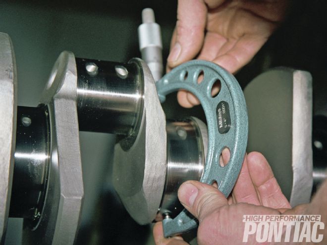 14 The crankshaft journal dimensions are confirmed.
The important thing for the HPP reader to understand is that the Butler stroker kit is internally balanced (equilibrium is accomplished by modifying the mass of the crankshaft) so a stock Pontiac flywheel/flexplate must be neutral-balanced or a neutral balance aftermarket piece is required. If this is not done, it will cause an imbalance condition.
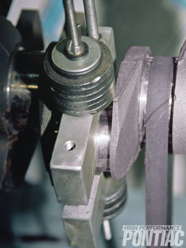 15 Bobweights are created to the exact value and then bolted to the crank rod journals.
By design, a piston-driven engine is flawed by its need to convert a reciprocating force into a high-speed rotational movement. Unlike a tire that spins only on its axis, the internals of an engine are dealing with reciprocating and rotating masses.
Rotational laws of physics are applied to the crankshaft, harmonic damper, and flywheel or flexplate, along with the big end of the connecting rod. The piston and companion components, along with the connecting rod from the midpoint to the small end, are identified as reciprocating. Rotating masses are affected by centrifugal forces while reciprocating bodies are under the control of the inertia theory. When balanced, the rotational components will possess no heavy areas that act on the crankshaft and try to pull it from its axis of rotation. The identification of mass differential is accomplished on a balancing machine.
The reciprocating components are required to possess the same mass as the others on multiple-bore engines. This is based on the theory of mass absorbing energy and, in turn, if all are of equal weight, the same inertial force will be applied to the crankshaft as each piston stops at top dead center. Because it’s not practical to add weight to the reciprocating parts, the accepted method of balancing is to weigh all the components individually and then remove material to match the lightest one.
Balancing of both rotating and reciprocating components adds longevity, power, and smoothness to the engine itself, and imparts the same qualities to any other components that are operated by it.
The first procedure in balancing is to gather all of the components. This includes the crankshaft, balancer, flywheel/flexplate and bolts, pistons, pins, pin locks, rings, bearings, connecting rods.
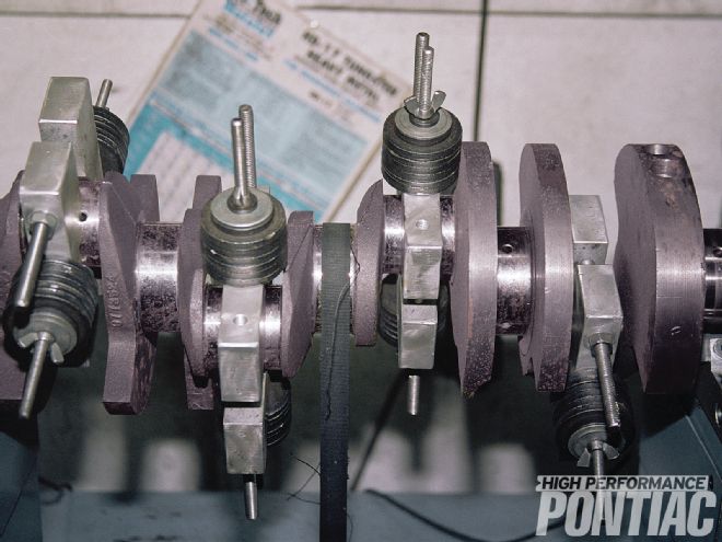 16 Here is a stock 455 crankshaft (not our Eagle forged crank) with all of the bobweight installed prior to spin testing.
Weight-matching the pistons and pins is first. The machinist will identify the lightest one with a highly accurate digital scale that reads in grams. Since the connecting rod shares both rotating and reciprocating functions, it requires a rod holding fixture so that each end can be weighed separately. Starting with the big end, all of the rods will be weighed with the results recorded. The balance pad on each rod will then be machined to bring them to the lightest value. The rod will then be turned around, the small end weighed, and matched to the lightest one by machining the balance pad on the pin end.
This not only weight matches all of these components, it gathers information to simulate these forces on the crankshaft when it is installed and spun in the balancing machine. Bobweights that have lead shot or washers are used to simulate the exact weight of the reciprocating mass.
The crankshaft is then mounted in an application-specific balancer with the bobweights attached, and spun by a belt drive to around 500 rpm. The balance machine reveals on a control panel the amount of inbalance and the position of correction dependent on whether weight will be added or removed from the crankshaft.
If weight is to be removed, it is customary to drill the crank on the counterweight at the point identified by the machine. The depth and size of the hole is determined by a drill chart that identifies the weight of the material removed from the hole. If mass is to be added to the crankshaft to compensate for heavier reciprocating components or increased stroke, then a hole is drilled axially to accept a heavy metal slug made of tungsten. It’s customary to press-fit and then weld the slug in place. Heavy metal installation usually shows a 2:1 ratio. If one gram of steel is removed, the area displaced will hold 2.17 grams of tungsten.
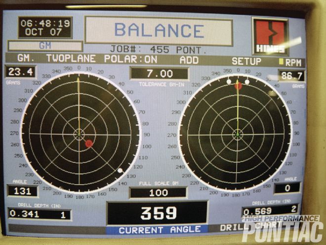 17 The Hines balancer displays a screen to identify where and how much mass needs to be removed or added to the crankshaft.
Many times a machine shop will cut corners to lower their engine price, only weight-matching the new rods and pistons and not balancing the crankshaft. This is not considered a balanced engine. The only thing you can say is that the reciprocating parts all weigh the same. Make sure that your engine shop balances the entire assembly and doesn’t just weight-match.
This now brings us to another concern—how fine should a balance be? It is the opinion of both the author and Craig Wise from RaceKrafters that any rotating assembly should be balanced as finely as possible regardless of the use it will see. Some engine builders leave more tolerance in the balance of a lower rpm engine then they would a high-rpm one. This logic is faulted since the amount of effort to finely balance the rotating assembly is only slightly more than a sloppy job, and the engine will know the difference. For this reason, have the shop confirm the amount of tolerance they will allow in the balance job before you hire them.
 18 The final step is to fine-polish the journals and then place the crankshaft in a sealed plastic bag to wait for installation in the block.
Now that the rotating assembly of the mule engine is complete, our next installment will cover the proper steps for machining a Pontiac cylinder head.