Of all the parts that have come and gone for the small-block Mopar, none are as venerated as the fabled W-2. Due to the work of airflow master Bob Mullen, the W-2 was truly revolutionary when introduced in 1976. It put the small-block Mopar on the map as a serious race engine-serious enough to take the NHRA Pro Stock championship in 1979 when Ford notable Bob Glidden fielded a Plymouth Arrow for one year. It was eventually rendered uncompetitive in that venue via a rule change favoring large displacement engines. Does it have any relevance these days? Here's the bottom line; it was great then and it's great today.
Originally, there were a couple of different versions of the W-2 and even more part numbers today, which has lead to some confusion. The W-2 heads were originally offered in two versions: the econo head and the race head. The valve length was the difference between the two versions. The production Mopar small-block engine has always had a relatively short valve length for the port configuration, leaving minimal room for valvesprings. The stock-installed height was 1.65 inches, too tight to run a high-lift cam without coil-bind problems. The original econo head used stock-length valves and rocker pedestals cast in the stock location.
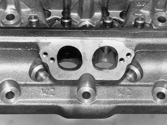
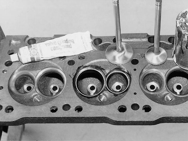 Iron heads are typically in a rougher state from the casting process than their aluminum counterparts with more casting irregularities, which can hurt flow. We were interested in seeing what they would do with a little cleaning up. Step one is to mark the valve seat location by painting the machined seat area in layout dye and lightly lapping the valves. This highlights the seat location, serving as a guide for the first stages of porting.
For race duty, a longer valve was used to fit the longer springs as required with high-lift racing cams. Move the tip of the valve up higher and the rockers will also have to move both up and away inward due to the valve's 18-degree angle from vertical. To accommodate the requirement for a relocated valvetrain, the race W-2s came with the rocker pedestals milled off and utilized separate stands and offset shafts to get the rockers in the proper orientation. That was the only difference; the ports and everything else remained the same. All W-2 heads feature wide, oval intake ports, which means the intake rockers must be offset so the pushrods will clear. As a result, W-2 heads need special offset intake rockers.
A recent addition to the W-2 lineup is a long-valve econo version, which represents the best of both worlds. It takes the long valve such as the old race head and gives all of the above-cited advantages, but has the pedestals cast in the relocated location so the rocker shaft bolts on without the separate stands. These heads are sold by Mopar Performance under PN P4529995 for the 2.02/1.60-inch-long valve econo version. At a retail price of $349.88 each for the bare castings, we believe they represented a bargain for the serious Mopar racer or street freak, so we ordered a set from Westoaks Dodge. To fill them out, we also ordered Mopar Performance's long-stem W-2 valves in the production 2.02-inch (PN P5249195) intake/1.60-inch (PN P5249197) exhaust sizes. The long-stem valves were about the same price as the standard valves. Going in, the W-2 combo also requires the special offset rockers we already mentioned, a W-2 oval port intake, and special headers to mate to the relocated exhaust ports.
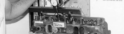
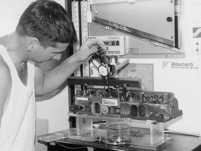
The Flowbench
We took our W-2 heads to Westech with the idea of running some baseline numbers on their Superflow 600 flowbench, then pulling out the carving carbides to see how they respond to porting. The heads were pulled out of the box and mounted to the bench, and we had our first set of numbers: 244-cfm peak intake flow at .600-inch lift and 140-cfm showing at .600-inch lift on the exhaust (Tables 1 and 2, column 1). The numbers compared favorably to what we've seen for aftermarket small-block Chevy heads on this flowbench and way better than a stock 360 head's 194-cfm intake, 128 exhaust.
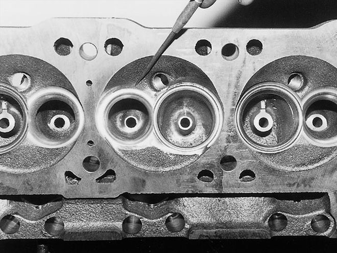
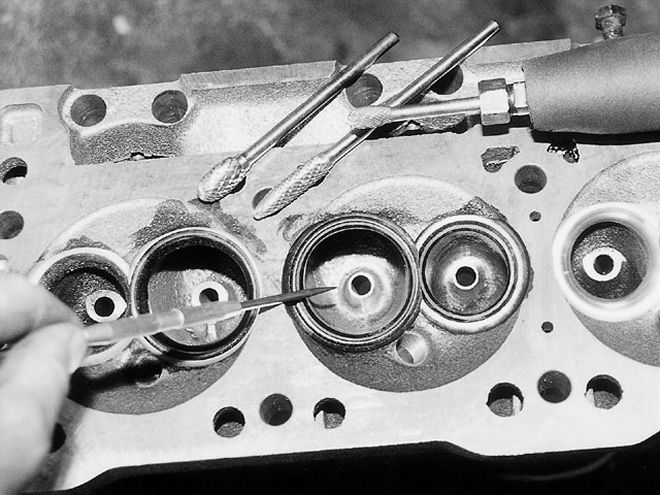 Going a little further, the valve-guide boss on both the intake (pointer) and exhaust ports were profiled as shown. This is getting into more serious porting work; it takes a good selection of carbide bits and experience with the cutter to achieve such a nice form. The result is another dramatic jump in flow.
With our base numbers in, we performed some basic porting. We knew the W-2s were capable of high airflow with full porting, but opted to take a step-by-step approach to see what they actually responded to. Our first step was to perform a simple blend where the production machining ends and the as-cast bowl begins. This is typically referred to as a bowl blend. Here we removed enough metal to take out the sharp ridge. While the exhaust port immediately responded with a peak flow of 163 cfm at .600-inch lift for a solid 23-cfm gain, the intake flow dropped to 241-cfm peak, at a lower .500 inch (Tables 1 and 2, column 2). What gives? Were we doing something wrong? Not quite. Observing how the flow built up, our peak flow didn't change much, but now it built up to peak sooner, meaning the port was working better; however, it wouldn't handle any more flow without separating. Typically, this would suggest some short-side turn blending was in order.
The Short Side
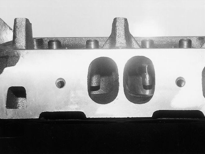
Ask top cylinder head porters if there's much to the short-side turn, the part of the port where the floor turns in toward the valve, and you may just hear, "It's all in the short side." When we looked at the shape of the short turn on the W-2, it had the form we're used to seeing in a modern race head: a generous radius with a high approach. No production head has this kind of raw material.
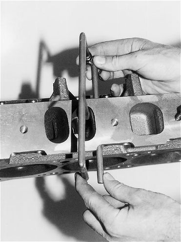 The intake runner has a couple of bulges on the straight wall: one where the pushrod intrudes and one where the headbolt goes through farther in the port. A Helgesen "E" tool from Doctor Air gauges the thickness of the material in the pushrod area. It works in practically any head and shows that most of the bulge could be removed. We opened the pushrod area and blended the headbolt bulge. The W-2s now had intake flow that topped all but the most exotic aftermarket Chevy race heads, all with much larger valves and ports.
We didn't go in and try to redesign the port with our cutters. Instead, we went in and blended this area out on both the intake and exhaust ports. The basic shape is near ideal, slightly lost in the rough cast iron. We cleaned it up, mildly profiled it, and reaped the reward: 270 cfm at .600-inch lift on the intake port and 181 cfm at .600-inch lift on the exhaust (Tables 1 and 2, column 3). After two small clean-up operations, the W-2s were flowing better than most of several aftermarket aluminum Chevy heads in the Westech files. In fact, it would take a reasonably well-executed, 2.14-inch valved, ported production 440 head to achieve that level of intake flow on this bench.
A Little Guidance
Next, we turned our attention to the valveguide boss, again both on the intake and exhaust ports. The guide boss on the as-cast W-2 isn't intrusive and is a far cry from the oversized hooked-over monster found in the intakes on all the premagnum production heads. There wasn't a serious amount of material to remove, but we became serious in working the area into a racy, rolled form with a minimal cross section.
The port bowl is much deeper in the W-2 than in the production heads, a design advantageous to airflow and thus the guide boss is further in. It takes some deft handwork to achieve a fine form as shown here, but the results were solid gains, increasing the intake port flow to 278 cfm at .600-inch lift and cranking 190 cfm at .700-inch lift on the exhaust (Tables 1 and 2, column 4). The W-2s were already moving serious air with most of the port as yet untouched.
Pinch And Bulge
Our next mods had to do with only the intake port. Though the W-2 has the pushrod largely moved out of the way, there's still some encroachment of the pushrod area into the port at the pushrod pinch. We gauged the thickness of the metal hanging into the port using a Helgesen "E" tool from Doctor Air and found material that could be removed. In fact, from about the midpoint of the pushrod pinch to the roof, the bulge could be removed entirely. Further along the straight wall, the port bulged inward to allow clearance for casting in the head-bolt hole. We hit the head-bolt bulge with a long carbide, blending it down on both the lead-in and off-side, considerably reducing the profile. We didn't sonic-check to see where the limit is. Instead, we cut until we used up our huevos. If you go too far, the head must be sleeved to fix it.
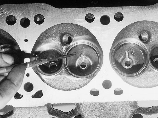
 The next trick was to blend the sharp edge from the deshrouding cut into the as-cast surface of the chamber (pointer). The intake preferred it at lower lifts, probably because the ridge just above the top cut of the seat was cleared, while the exhaust didn't seem to care.
These mods brought the intake port into the etherland of flow for a 2.02 valve, with a peak now showing 295 cfm at an intermediate checking height of .650-inch lift (Table 1, column 5). Westech does extensive testing on a variety of aftermarket heads on this bench, and we had some fun comparing the flow of our relatively small-valved W-2s to the recorded flow of some exotic big-valved aftermarket heads for the brand-X competition. We were in serious company and still had 70 percent of the port in as-cast condition.
Clean Sweep
With the high-port flow we achieved so far, it seemed time to direct some attention to the chamber. The valves in any inline valved engine are shrouded by the chamber wall. To minimize the shrouding, take a sweeping cut of the chamber adjacent to the valve. The limit here is the head gasket line, less approximately .020 inch, allowing for compression of the fire ring. The factory-machined W-2s had quite a lot of meat between the valve and the gasket line. The best way to open up the chamber is on a seat-cutting machine; the Serdi Seat and Guide machine is considered by many to be the best for this. David Anton of APT was kind enough (again) to allow us to borrow his Serdi to make the required cuts.
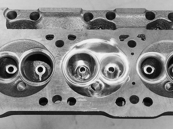
 Though the W-2s were already delivering outstanding numbers, we hadn't gotten into the heavy porting work yet. We went in for full-bowl work next, cleaning the rough surface and blending it into a smooth form toward the port exit. By itself, this is usually referred to as pocket-porting. The W-2's basic shape is already correct, so it was more a matter of cleaning up than drastically altering the shape. With the full pocket work performed to the intake (pointer) in addition to our previous steps, we caught 300 cfm on the intake port at .650-inch lift. With similar work, the exhaust side was now solidly beyond 200 cfm.
Back at Westech, we had the Superflow bench back in service and found little gain in peak intake flow from the exercise, but quite a boost from .300 to .500-inch lift (Table 1, column 6). The exhaust side showed gains all the way to the top of the lift curve and, like the intake, showed the biggest boost in the mid-lift flow figures (Table 2, column 6).
Machine-sweeping the chamber left a pronounced sharp edge where the freshly cut areas met the as-cast chamber. For the next test, these edges were blended to make a nice transition from the machined to the as-cast areas, resulting in some additional midrange gains on the intake and a few odd cubic feet per minute plus and minus on the exhaust (Tables 1 and 2, column 7).
 With everything completed from the chamber down to the bowl, there was nowhere left to go but to the straight part of the port: the runner. The old Pro Stock-style porting job opened the runner to the maximum cross-sectional area, altering the shape to a large rectangular port. In light of our intended street/strip application and standard-sized 2.02-inch valve, we lightly cleaned the surfaces and called it good enough. Nothing was gained here, indicating the port runner really didn't represent a restriction with this valve size. With 300 cfm already making its way past the 2.02-inch valve, the runner seems to be nearly ideal for the valve size as delivered, so seeing the numbers wasn't surprising.
Deep Pockets
Other than the minor bowl blend we started with, most of the bowl of the port was still virgin, uncut cast iron. It was time to go in for a deep-pocket port, blending the bowl and smoothing the transition from the bowl into the port runner. The deep pocket porting was performed on both the intake and exhaust ports, leaving no as-cast surface in the port bowl when finished. The material removal here was relatively modest. Since the W-2s have a nice form as-cast in the bowls, there's no need to redesign the shape with the cutter. The bowl work resulted in a nice boost in the mid-to-upper-lift flow, with peak intake flow now cracking 300 cfm at an intermediate checking height of .650 inch (Table 1, column 8). The W-2s were astounding.
On the exhaust side, the same approach of fully blending the bowls for a deep pocket port brought a sharp rise in mid-to-upper-lift flow. We now handily topped 200 cfm with an open-port exit (Table 2, column 8). Often, flow figures are quoted with an exit pipe in place to simulate an exhaust header. Sometimes exhaust port flow will show a substantial increase with a pipe, while some ports don't show much change. Tested with a pipe, the W-2 port picked up an additional 10 cfm.
Full Port
Our next step was to aim for the full port. Not to be mistaken for a maxed-out large cross-sectional-area porting job, the plan here was to work only the entire surface of the port, blending and smoothing with the carbide cutter. Only a minimal amount of material was removed from the port floor to clean it up, while the roof and the port walls were blended to provide a smooth transition all the way from the manifold face to the already cut pocket. The results were minimal, with the overall port flow basically unchanged from the previous test on both the intake and exhaust side (Tables 1 and 2, column 9). We already found most of the impediments to flow in the areas already hit with the cutter, and all that remained was window dressing.
 The last step was to go in with No. 60-grit abrasives and polish the rough carbide-cut surface of the entire port. The polishing process will reveal defects, dips, bumps, and irregularities you can't see in a rough carbide-cut surface. By the time it was completed, the port was as slick as a baby's bottom and flow was up big time.
Up until now, all of the steps were performed with nothing finer than the rough carbide cutter. In fact, special custom-made, coarse-pitched carbide cutters were used, which make porting cast iron almost as fast as reworking an aluminum head. The upside is speed; the penalty is surface finish. To put the finishing touch on the ports, the rough carbide cuts must be smoothed with much finer cartridge sanding rolls and flap wheels. To quickly smooth out the rough surface, we use No. 60-grit abrasives. To make it easy to gauge progress, the entire inner surface of the port is painted with a guidecoat of layout dye (Dychem).
Used for this purpose, the polishing process entails much more than simply improving the surface finish. A substantial amount of blending is accomplished throughout the port, while a significant amount of material is removed along the way. What's left is a smoothly finished port, blended for minimal distortion and contour irregularities. Flow gains from this final procedure can be substantial and the test W-2 port were no exception, showing a dramatic increase in flow. The intake port now showed a peak of 312 cfm at .700-inch lift and the exhaust was blowing out 215 cfm (230 with pipe). Moreover, flow was up across the entire curve with both ports (Tables 1 and 2, column 10).
 The icing on the cake was to polish the chamber. No flow gains here, but it will reduce the tendency for detonation by curbing hot spots and help thermal efficiency. These ported W-2s put the hurt on practically any CNC-ported aluminum whizbangs the Chevy guys can buy.
To cap things off, the chamber was revisited for a polishing. This procedure helps minimize detonation and preignition-promoting hot spots, while helping to retain normal combustion heat for better thermal efficiency. Port flow was virtually unchanged for the intake port, but the exhaust port registered some minor gains at certain lifts (figures not given in tables).
Spectacular
Were we pleased with the flow delivered by the W-2s? Compared to the fat book of flow results from small-block Chevy heads tested at Westech, nothing was even in the same league. The ported W-2 outflowed practically every aftermarket aluminum Chevy heads, whether as-cast, CNC-ported, or running much bigger valves. Only the ultra high-end, CNC-ported, rolled-deck heads with huge valves and more than half again the port volume topped our numbers. The icing on the cake was when our flow work was interrupted for a test on a fully ported Ford 460 aluminum head. With intake ports large enough to roll a tennis ball down and sporting monster 2.25-inch valves, we were quiet when the peak flow numbers came in at less than our little W-2's intakes. Perhaps they missed the short turn.
Port Flow Summary • Flow-Tested By Steve Dulcich
Westech's Superflow 600 Flowbench (with FlowCom)
All Tests at 28-inch water depression