It's always interesting how one aspect of a project affects another. Deciding to slap a supercharger on our LS327 engine is a great example of this, though probably a bit on the exaggerated side. Obviously, our plans of using a simple four-barrel carb and intake were out the door, as was the plan to keep it simple with only a small ECU to control the timing. One thing led to another and here we are setting up a drive-by-wire throttle pedal and throttle body.
When the parts showed up thanks to Carl Lutes and the guys over at Guaranty Chevrolet in Santa Ana, California, one thing was certain: we needed to swap out the plastic pedal pad. A quick email to Brian Downard at Lokar got us squared away with one of their new black billet aluminum Direct Fit pedal pads. When Brian asked what we were planning on using for the brake and clutch pedals, I told him we were planning on keeping them stock. He mentioned that Lokar was coming out with a Direct Fit line of pedals arms that would drop right in and replace the 1967-72 C10 stockers. Designed to match the throttle pedal pad we were now planning on using, the billet aluminum design would also lend the contemporary performance that the inside of our cab needed.
I had also planned on replacing all of the truck's brake lines since we hadn't done so when we did the first iteration of the build a few years back. The master cylinder was also showing its age, and since I needed to add a small master cylinder to actuate the new hydraulic clutch, I figured I might as well replace the brake master with a unit that matches the clutch.
Several guys around the office swear by their manual master cylinder brake setups on their street cars so I figured I'd give the guys at Wilwood a call to see what the ticket is to getting a nice pedal feel without sacrificing stopping power or effectiveness. Turns out the key to achieving a good, firm pedal without a bunch of leg effort is to start with a pedal ratio of at least 6:1, which is the ratio of Lokar's Direct Fit pedal arms. From there, it's a simple matter of matching the requirements of the front and rear brakes to the master cylinder bore. For our 1968, that turned out to be a 7⁄8-inch master to feed the 13-inch front and 11-inch rear disc brakes.
Installing the brake and clutch pedals couldn't have went any smoother, while the throttle pedal needed to be modified slightly before it would bolt up to a fresh set of holes drilled in the firewall. The brake master cylinder bolted up to the existing lower studs and slid right up against the firewall without issue, but the clutch master cylinder, being an added part, required another set of fresh holes to be marked and drilled out on the firewall. A custom linkage set to mate the pedals with their respective masters and we soon had ourselves a pedal setup whose performance will be the envy of any sports car and looks good to boot!
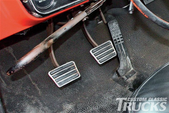 1. Aside from the fact that the pedal set in our C10 is pretty beat up, the throttle pedal needs to be swapped out for a GM drive-by-wire unit and the clutch pedal needs to be converted to a hydraulic setup. Instead of modifying the existing set, we opted to go with Lokar’s complete kit that’ll sort out everything in one move.
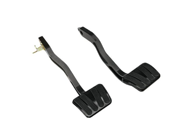 2. To replace our busted pedals, we’ll be using a set of Lokar’s Direct Fit brake and clutch arms (XBCA-9508) with standard pads. Designed to replace the original pedal arms, these billet aluminum beauties utilize a bronze pivot bushing for increased durability and their unique styling complements other Lokar products. The brake pedal is shown on the left, with the brake light switch tab at the top, while the clutch pedal is on the right.
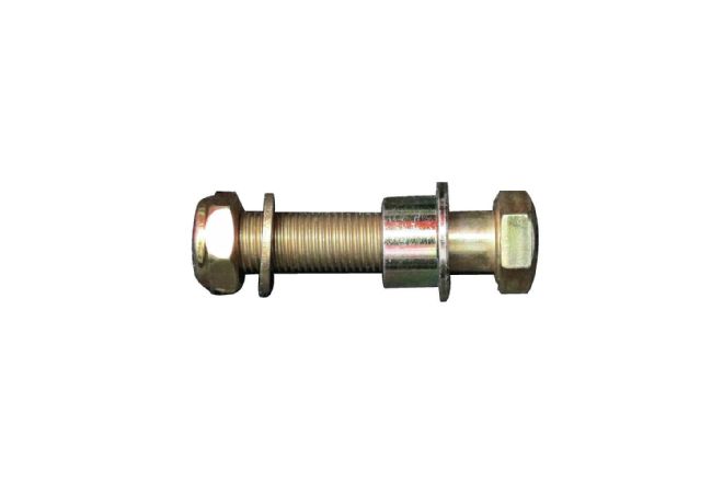
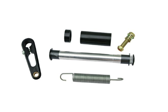 3. The pedal set comes with everything needed to swap out the stock pedals, with the exception of the brake pedal support sleeve, which will have to be cleaned up and reused as it’s a non-consumable item. Clockwise from left is the clutch rod lever, ½- and 213⁄16-inch Delrin spacers, 3⁄8-inch hex head fastener assembly with brake pedal rod end bushing, splined shaft, nylon bushings, ¼-20-inch fasteners and end washers, and clutch pedal return spring.
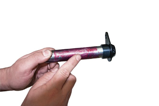
 4. It’s important to test-fit the new assembly with the original brake pedal support sleeve before attempting installation. Due to manufacturing tolerances and possible differences between OE and replacement parts, some brake pedal sleeves may be too tight. After a quick wire wheel cleaning and paintjob, I test fit the sleeves and brake pedal in their installed arrangement. Everything checked out, so we’re off and running.
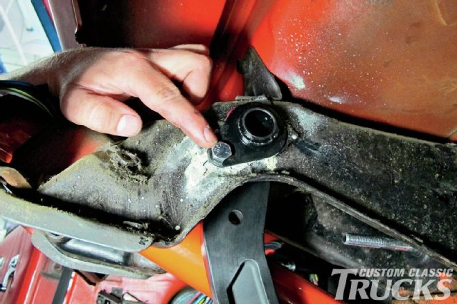
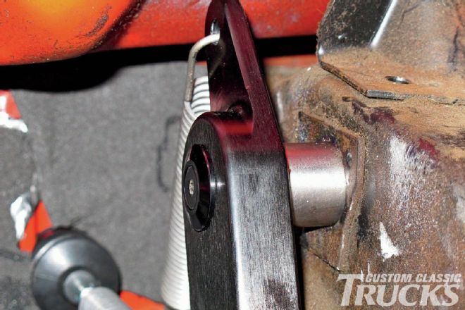
 5. Before we get ahead of ourselves, I need to drill a hole in the clutch pedal arm so that I can mate it to the Wilwood hydraulic master cylinder. The Lokar pedals are designed as a direct, OE replacement part and as such, are designed to actuate the stock clutch rod linkage via the clutch rod lever that installs opposite the clutch arm. I’m going to mount the clutch master cylinder on the firewall next to the brake master cylinder, so matching the hole in the brake pedal ensures the two master cylinders are mounted level on the firewall. It also works out that the ratio for the brake pedal works out for the clutch as well. With the pedals aligned, it’s a simple matter of using a transfer punch to mark the clutch arm before it’s drilled to size.
 6. This is the stock brake pedal support sleeve that I cleaned up and painted the end that’s exposed. A thin film of grease is applied before it’s slipped through the right side of the pedal hanger bracket under the dash. Next, the ½-inch Delrin spacer is installed, followed by the new Lokar brake pedal, and then the 213⁄16-inch Delrin spacer. The support sleeve is then pushed completely through the pedal hanger bracket so it sits flush against the retainer plate.
 7. Next, the retaining fastener is installed and tightened, securing the brake pedal support sleeve to the hanger bracket.
8. If we were mating the brake pedal to a stock setup, we’d next install the provided brake pedal rod end bushing assembly onto the pedal. Our setup is slightly unique, however, so we’ve got a different way to mate up the pedals to the master cylinders, which we’ll cover shortly.
7. Next, the retaining fastener is installed and tightened, securing the brake pedal support sleeve to the hanger bracket.
8. If we were mating the brake pedal to a stock setup, we’d next install the provided brake pedal rod end bushing assembly onto the pedal. Our setup is slightly unique, however, so we’ve got a different way to mate up the pedals to the master cylinders, which we’ll cover shortly.
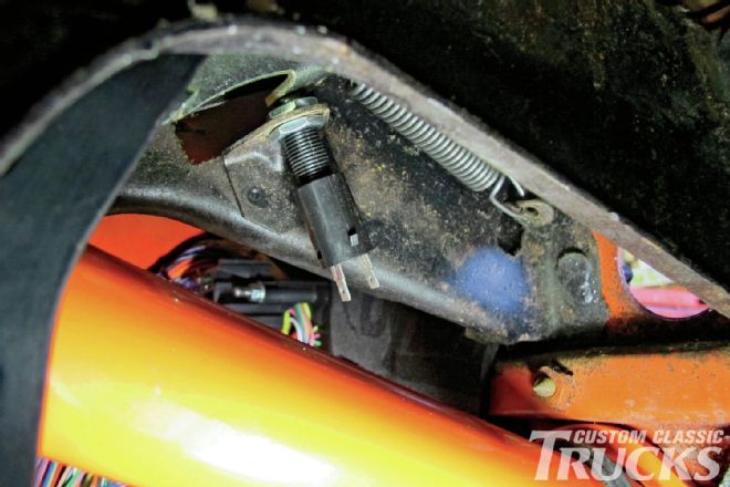 9. A new brake light switch was added as cheap insurance, which we’ll adjust when everything is said and done. You can also see the stock brake pedal return spring above it that I cleaned up and reinstalled.
 10. To install the clutch pedal arm, first the splined shaft needs to be lightly lubricated, as do the two nylon bushings, one at each end. Then the assembly is slid into the brake pedal support sleeve until the splined ends are protruding from each side.
 11. Next, the clutch pedal is slid over the splines and held in place using the provided aluminum washer and ¼-inch fastener. A little thread locker on the fastener is good insurance. The clutch pedal return spring can now be attached to the ear at the top of the pedal and the pedal hanger bracket near the firewall.
 12. At the other end, the clutch rod lever is slid over the splined shaft and held in place just like the clutch pedal. The pinch bolt is tightened last, though in our case the rod lever is only acting as a spacer since we won’t be using the stock clutch linkage.
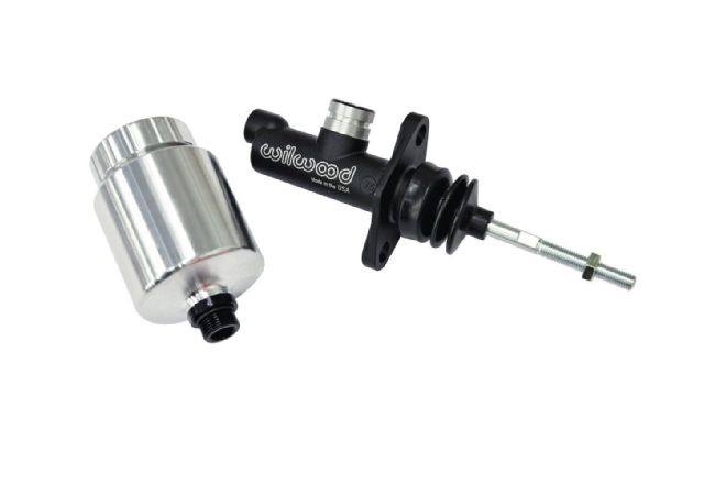 13. To actuate the hydraulic throwout bearing on our Tremec, we’ll be using a Wilwood ¾-inch bore master cylinder (260-10282) coupled with their new billet reservoir (260- 12696). This combination will complement the brake master setup perfectly, but a little bit of custom fabrication is in order since our C10 utilized a mechanical stock linkage setup originally.
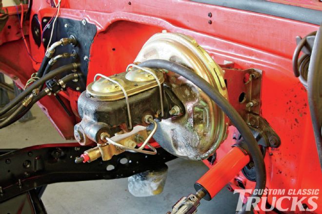 14. After two years of subsequent thrashing, our master cylinder/brake booster combo was starting to look pretty ragged. Since the plan called for adding a Wilwood master cylinder for the clutch, I figured I’d use that as a good excuse to swap out the brake master for a Wilwood unit as well.
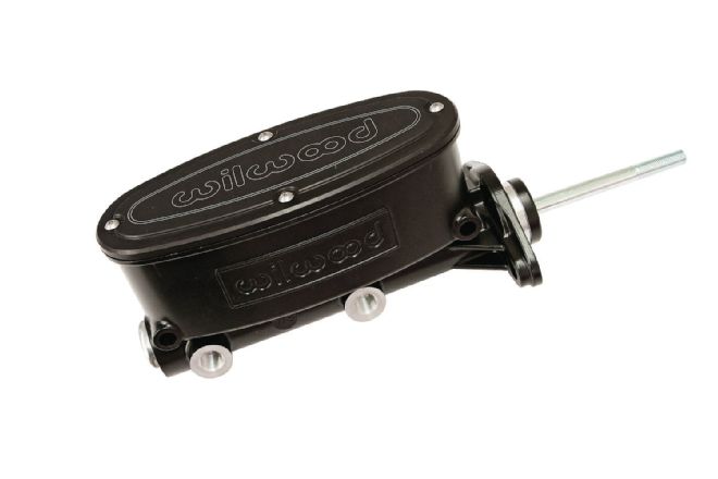
15. I’ve heard great things about the ability to better modulate and control the braking by using a manual master cylinder over a vacuum-boosted unit so I thought I’d give this Wilwood unit a try (260-9439-BK). The 7⁄8-inch bore is ideal for manual disc/disc setups by increasing the pressure to the calipers without the need of extra pedal force over a larger bore master. Dual ½-20 UNF ports on either side give plenty of options when it comes to running the brake lines down the firewall.
14. After two years of subsequent thrashing, our master cylinder/brake booster combo was starting to look pretty ragged. Since the plan called for adding a Wilwood master cylinder for the clutch, I figured I’d use that as a good excuse to swap out the brake master for a Wilwood unit as well.
15. I’ve heard great things about the ability to better modulate and control the braking by using a manual master cylinder over a vacuum-boosted unit so I thought I’d give this Wilwood unit a try (260-9439-BK). The 7⁄8-inch bore is ideal for manual disc/disc setups by increasing the pressure to the calipers without the need of extra pedal force over a larger bore master. Dual ½-20 UNF ports on either side give plenty of options when it comes to running the brake lines down the firewall.
 16. Brand new from Wilwood is their Adjustable Combination Proportioning Valve with mounting bracket (260-13190). Specifically designed to work with their tandem master cylinders, it simplifies mounting, fluid circuit plumbing, brake light wiring, and brake bias adjustments on trucks equipped with brake system upgrades. Bias proportioning adjustment is provided in the rear fluid circuit only to allow adjustment of the rate of increase in rear brake line pressure, relative and proportionate to the increase in front brake line pressure. This prevents the rear brakes from locking up before the front and provides the flexibility to further adjust the amount of pressure the rear brakes receive. A single inlet for the front and a single inlet for the rear simplify installation, while a pair of front outlets allow for flexibility when it comes to running the front brake lines. A single rear outlet allows for rear brake plumbing. A brake light switch is included and installed on the front of the combination propor
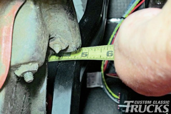 17. Mounting the Wilwood brake master cylinder is simple as it bolts straight up to the existing lower two studs from the stock master cylinder setup. Mounting the clutch master, however, takes a little more time. The first step is to measure the distance between the brake and clutch pedals. This will dictate where the center of the clutch master will locate relative to the brake master.
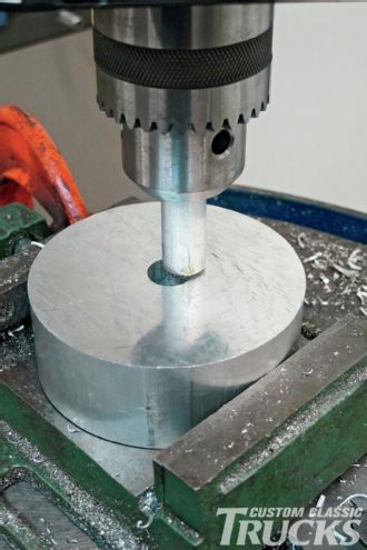
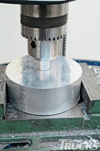
 18. Center to center was about 4¼-inches, so that’s where we’ll mark the center of the clutch master cylinder mounting location. We’ll also want the brake and clutch rods parallel and level so that the masters are level on the firewall. This is why we drilled out the clutch pedal arm to match the existing hole on the brake pedal for the linkage. A hole saw is used to cut the center opening for the clutch master cylinder, then the mounting holes can be marked and drilled.
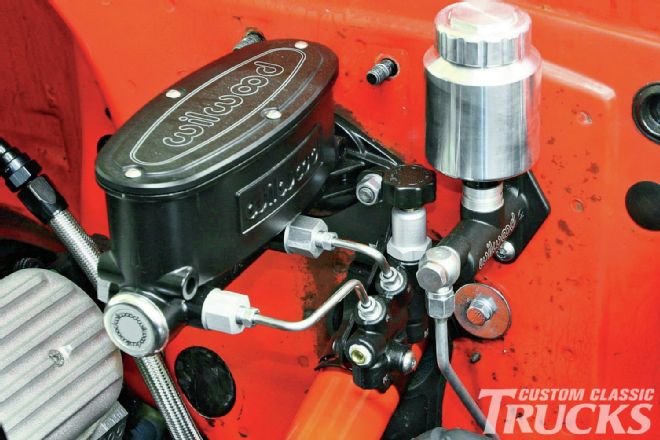
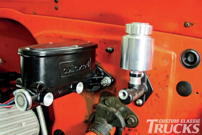 19. With the clutch master cylinder mounting sorted, both masters can now be bolted into place. Note that the centerline of both is on the same plane.
 20. With the master cylinders in place, it’s time to mate them to the pedals. Unfortunately, there’s quite a distance between the mounting hole on the pedals and the pushrod on the master cylinder. Although there are kits available to solve this problem, I opted to make one myself for each pedal out of a piece of solid aluminum stock, a rod end, and a pair of jam nuts.
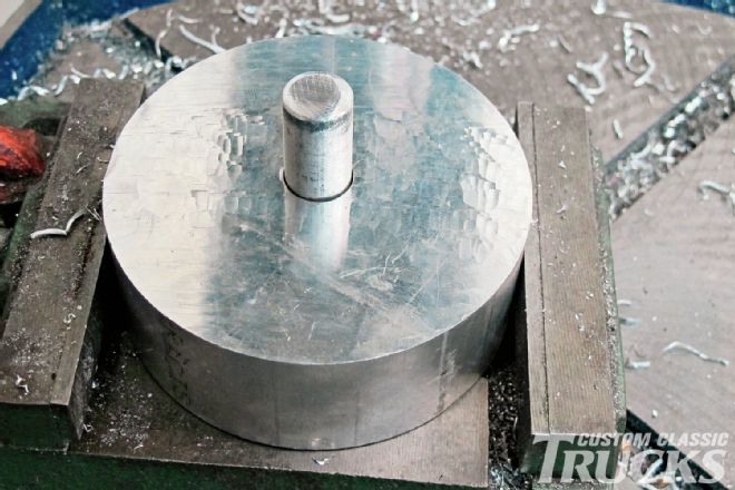 21. Drilling a piece of aluminum round stock in the lathe would be a simple task. Unfortunately, my lathe was on a pallet getting ready for a move, so I opted to do it the hard way, which is probably how most of you guys would have to tackle something like this anyways. Since freehand centering an aluminum bar in a drill press is pretty difficult, I made a jig that will hold the bar while it’s being drilled. The hole in the jig is drilled to a slip fit so that the bar fits fairly snug.
 22. The jig is placed in a vise while the bar is placed in the chuck of the drill press. The vise is then moved until the bar and jig align perfectly, then a C-clamp is used to lock the vise in place.
 23. If the drill press can travel smoothly, inserting the bar without snagging the jig, the drill press is centered with the hole nicely.
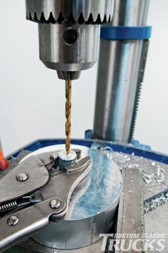 24. Then, the bar is inserted in the jig’s hole and a pair of Vise-Grips are used to prevent the bar from rotating while each end is drilled to size.
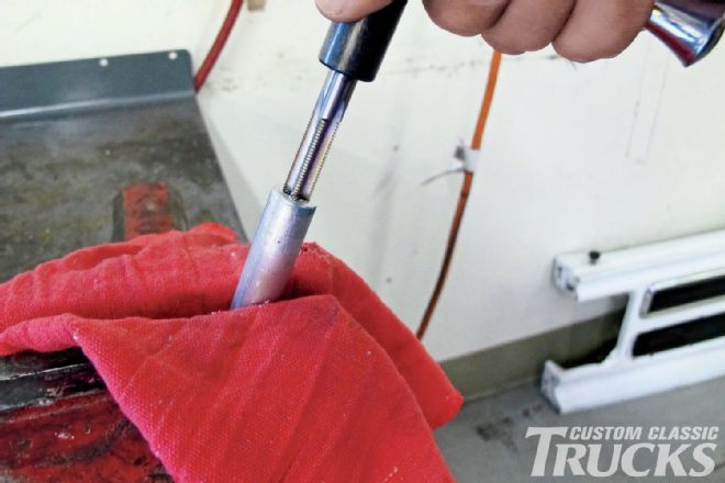 25. The pushrod on the brake master cylinder is 3⁄8-24-inch while the pushrod on the clutch master cylinder is 5⁄16-24-inch; so on one end of each bar, I drilled the hole to coincide with either sized tap. The other end I tapped with a left-hand 3⁄8-24 tap to mate to the rod end after drilling accordingly.
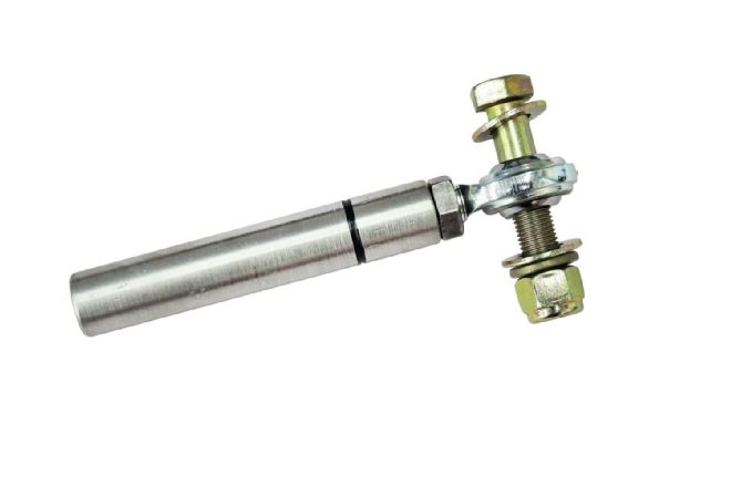
26. Here’s the finished spacer with the left-hand thread rod end and jam nut attached. Note the small groove I added to mark the left-hand side.
25. The pushrod on the brake master cylinder is 3⁄8-24-inch while the pushrod on the clutch master cylinder is 5⁄16-24-inch; so on one end of each bar, I drilled the hole to coincide with either sized tap. The other end I tapped with a left-hand 3⁄8-24 tap to mate to the rod end after drilling accordingly.
26. Here’s the finished spacer with the left-hand thread rod end and jam nut attached. Note the small groove I added to mark the left-hand side.
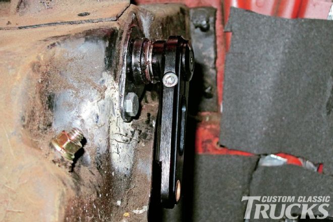
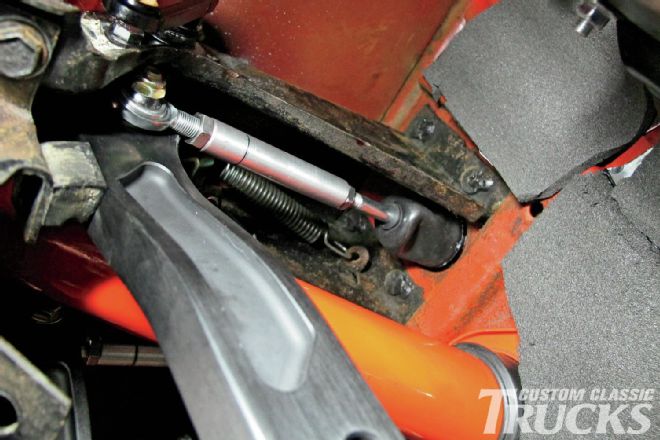
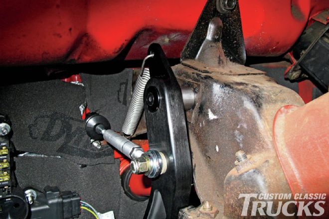 27. And here’s the new spacer setup in place. I used thread locker to ensure nothing comes loose or gets sloppy.
28. With the pedals mated to the master cylinders, I then mounted the adjustable proportioning valve using the bracket and lines Wilwood supplied. I also picked up a couple tube and nut fittings so that I could fab up the hydraulic clutch line as well. We’ll cover that as well as the brake line fabrication in an upcoming issue.
27. And here’s the new spacer setup in place. I used thread locker to ensure nothing comes loose or gets sloppy.
28. With the pedals mated to the master cylinders, I then mounted the adjustable proportioning valve using the bracket and lines Wilwood supplied. I also picked up a couple tube and nut fittings so that I could fab up the hydraulic clutch line as well. We’ll cover that as well as the brake line fabrication in an upcoming issue.
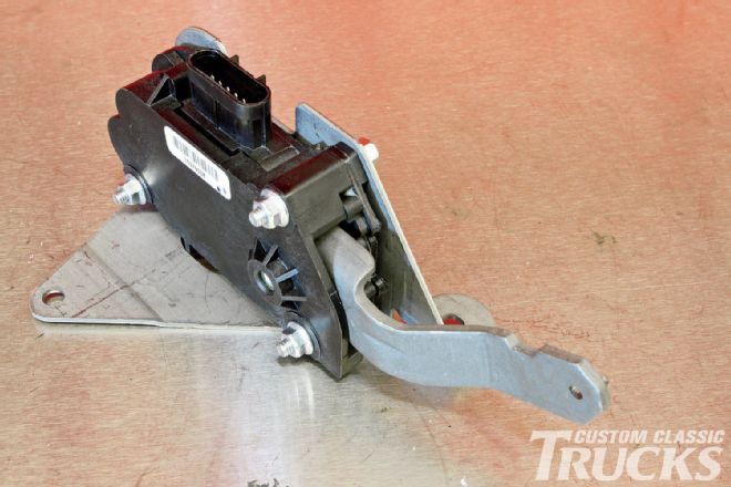
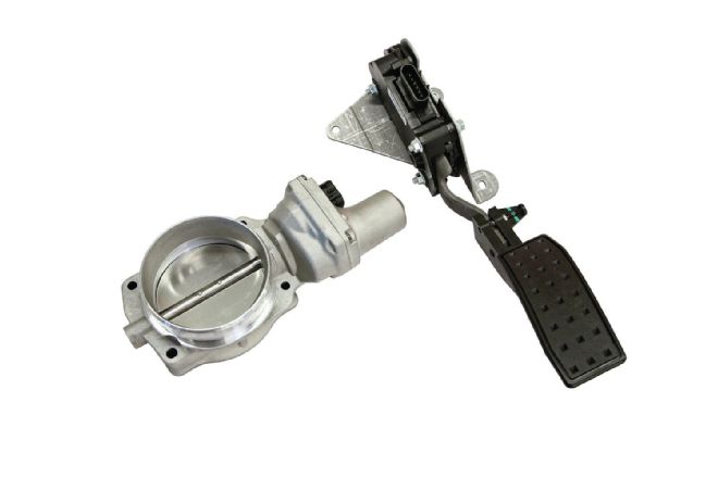 29. As I mentioned before, one of the contributing factors in swapping out the original pedal setup was the fact that we planned on using a Lokar pedal on our DBW or drive-by-wire throttle setup. Pictured is the GM two-channel throttle body (#12570790) and DBW throttle pedal (#10379038) that’s required by our Holley Dominator TorqStorm supercharged LS engine. We picked up both items at our local GM dealer, Guaranty Chevrolet. Thanks Carl!
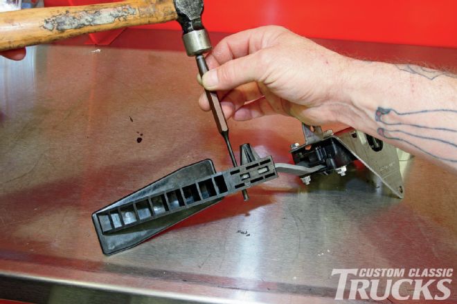 30. The bulky Cadillac plastic pedal that comes as standard doesn’t really lend itself to an old truck aesthetic, so we’ll be swapping it with a Lokar item that matches the brake and clutch pedals. The roll pin that secures the pedal must be driven out first.
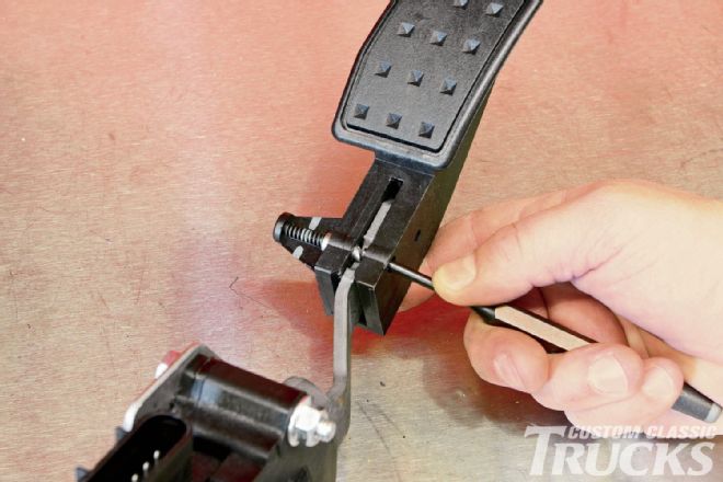 31. Then another spring-loaded pin is depressed so that the pedal can be removed from the arm.
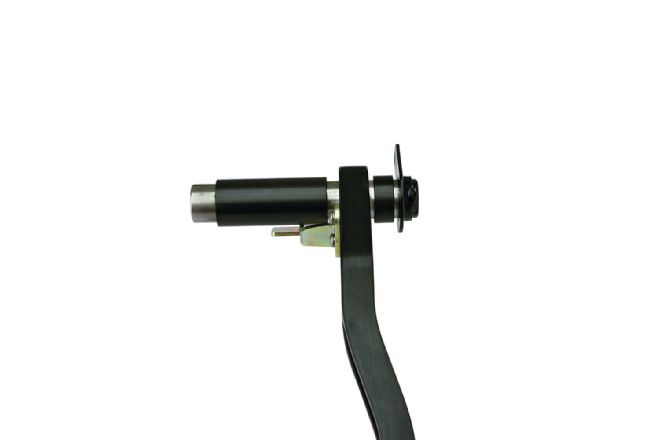
 32. Here’s the DBW pedal assembly, sans stock pedal.
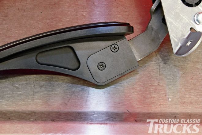 33. Instead of using the stock roll pin method, Lokar’s Direct Fit throttle pedal pad (#XDBW-6200) uses a pair of flathead screws that retain the assembly.
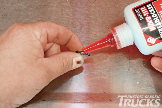 34. Permanent thread locker on these screws is good insurance.
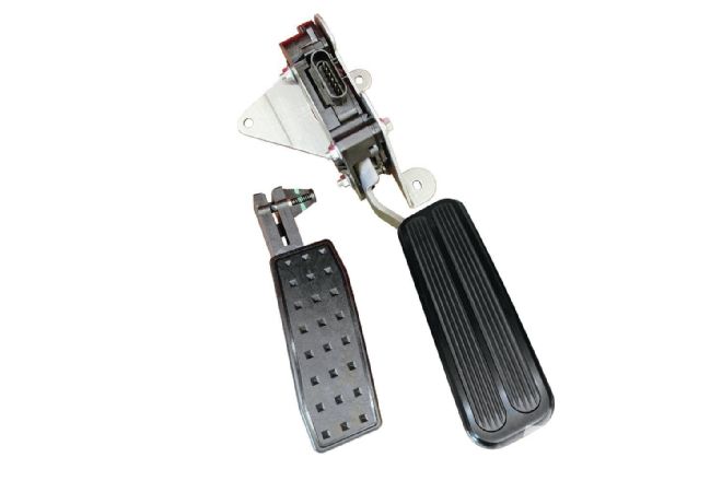 35. When it comes to good looks, the old plastic GM pedal is no match for the new billet Lokar pedal pad, not to mention it will match our brake and clutch pedals perfectly and provides a non-slip surface for safety.
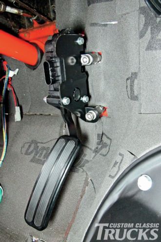 36. Mounting the pedal was a bit tricky and required a few modifications to the stock steel bracket, but after a few spacers were whittled out and a few holes drilled in the firewall, I had it mounted in the perfect spot.
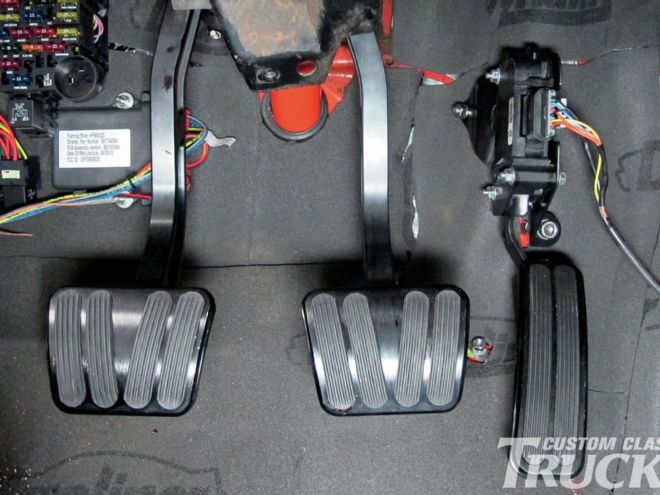
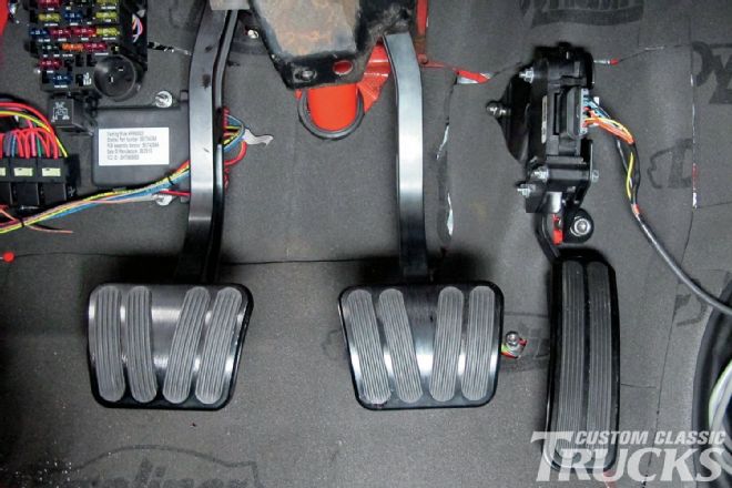 37. Here’s a shot of the three pedals, installed and ready to rock! At this point, I’ve just started the wiring so no carpet is installed yet, but you can already see how nice the pedals match each other and how lucky we got with the throttle pedal location.