Most of us just glaze over at the thought of actually installing an electrical system in our project car. Those bundles of multi-colored spaghetti are just more than many of us can handle. Maybe wiring seems confusing because, unlike fuel, cooling, oil systems, etc., we can’t see the electricity flow. Wiring your hot rod can be straightforward. The hardest part is running the wires neatly and avoiding sharp, moving, and hot objects.
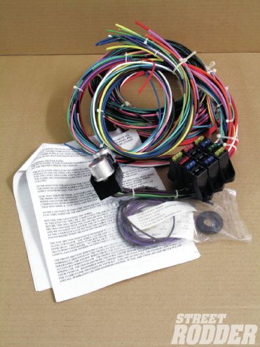 Rebel Wire eight-circuit wiring kit as it came out of the box; fuses, grommet, wire ties, fusible link, and most important—instructions.
Today’s aftermarket wiring kit manufacturers, American Autowire, Keep It Clean Wiring, E Z Wiring, Haywire, Kwik Wire, Painless Performance Products, Rebel Wire, Ron Francis Wiring, and others, have made the process of wiring your street rod extremely easy. With labeled wires, easy-to-follow instructions, and smaller, more compact units, the task of wiring a hot rod in one’s garage has become relatively simple.
In the application on the following pages we are dealing with a basic, no frills hot rod, meaning no power windows, no power door locks, no electric trunk, no heat/air, just the basics. Knowing this we searched for a simple no-frills wiring kit. While there are many such wiring kits out there, we chose a kit from Rebel Wire.
Assembled in America from American-made components, the Rebel Wire kit is a simple, eight-circuit kit that handles the lighting, ignition/engine starting, gauges, charging system, as well as radio, wipers, heater, and horn. Rebel Wire also offers a nine-plus three-circuit kit, and a 20-circuit kit for the highly optioned at-home project. In addition to the basic wiring kit we purchased a fan relay kit. Since we were not using a GM column or an aftermarket column patterned after a GM column, we purchased a turn signal switch from American Autowire.
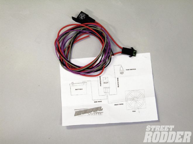
 We added a Rebel Wire fan relay to our original order. This relay is not included in the wiring kit and we felt it was important to install a relay on the electric fan.
The tools required in wiring a street rod are pretty basic: wire cutters, a wire stripper, screwdrivers, and a heat gun to seal the heat shrink tubing. (We do not recommend a cigarette lighter or matches for this task, but we have used a flame on occasion.)
Depending on what comes in your wiring kit and how you plan to connect wires, route wires, etc., you may need some additional hardware. In our case we needed an assortment of crimp connectors, an ignition switch, a battery disconnect, a light and turn signal switch, a horn button, several dual-row barrier strips, several jumper strips, and some heat shrink tubing. (Note: 3M makes a standard heat shrink tubing and heat shrink tubing lined with a sealer. We located the sealer type of heat shrink tubing at a local boat supply store. The sealer in the tubing makes a waterproof seal, which is good, especially in an open car.)
Armed with our Rebel Wire kit, instructions, and our additional hardware we set out to wire our street rod. The first decision is where to mount the fuse block. The normal mounting spot is under the dash on the driver side. We chose to mount the fuse block under the dash on the passenger side. We felt that in our case that would allow the easiest access to the fuse block, the most room to bundle and run the wires (not dealing with the steering column, throttle linkage, and the clutch and brake pedals).
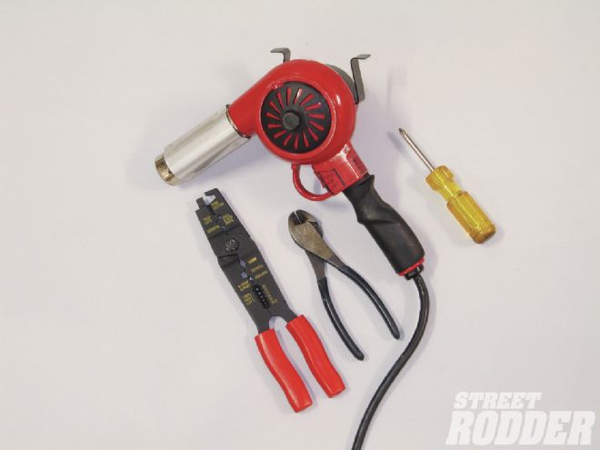 These are the basic tools required to install a wiring kit: crimping tool, wire cutters, heat gun, and a screwdriver.
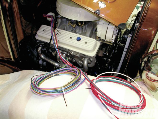
We mounted the fuse block and the flasher/relay panel to a piece of PVC board and secured the board to an underdash support. The next step was to cut a 1-1/4-inch hole in the firewall to pass the harness forward. The kit came with a grommet to fit this hole and the wires were neatly bundled in a manner that allowed us to separate the wires that were required to go to the engine compartment.
Next, we separated the front wiring harness into smaller wiring harnesses. Since the wires are marked every 6 inches it was a simple task to separate them into smaller bundles based on where they were to be used. We used the supplied wire ties to form the various harnesses. (Note: There are enough wire ties in the kit to do the job, but since we feel strongly about neatness, we redid many of the harnesses as we progressed and that required additional wire ties.)
The front master harnesses consisted of a headlight and starter/ignition harness, while wires for gauge sending units, fan wire, electric choke wire, coil wire, etc., are also supplied.
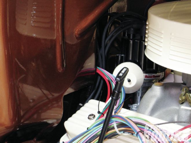 A 1-1/4-inch hole was drilled in the firewall and the supplied grommet was installed. The front wiring harness was then fed through the hole.
The wires were then routed to the appropriate connections via the instructions. After the individual wires were cut to the desired length, the appropriate terminal ends were crimped in place. (Note: There is a correct and an incorrect way to crimp the terminal ends. The seam in the terminal end should face away from the dimple portion of the crimping tool, thus the dimple, or the part that crimps against the wire, is solid.) Heat shrink tubing was used at each terminal end. Shrink tubing adds strength to the connection, makes the connection waterproof, and adds to the professional look of the finished wiring. (Note: In most cases the shrink tubing will need to be slid over the wire in its pre-shrunk condition prior to installing the terminal end.)
We chose to build a gauge wiring harness rather than connect the wires directly to the gauges. Since gauges normally are removed from the front this allows the gauges to be installed and removed by disconnecting the gauge harness from the electrical harness, instead of laying on your back, under the dash, installing or removing the nuts that secure the gauge wires. The construction of this harness only required us to cut the individual wires and install bullet-style connections to the ends of the cut wires. The reconnected wires remain color-coded and marked.
After installing the gauges in the dashboard, with the gauge wiring harness attached, we routed the various gauge wires (temperature sending unit, oil pressure sending unit, etc.) that are part of the wiring harness to the gauges.
 We split the front wiring harness into smaller harnesses, a headlight harness, a fan harness, an alternator harness, a starter solenoid harness, and an ignition and gauge-sending unit harness.
The electric speedometer wires were separated and paired (twisted together) per the gauge instructions. One of the twisted wires was connected to the sending unit in lug on the speedometer, while the other wire was attached to the ground lug. A separate chassis ground was run from the speedometer ground lug to a chassis ground. The speedometer instructions suggested that the twisted wires not be run with other wiring, as that may cause interference with the electric speedometer.
The ignition switch was purchased from a local parts store. The switch is rated at 30 amps, and has the power-in, accessory, ignition-on, and start terminals. Per the wiring kit instructions the appropriate wires were connected to the marked terminals.
An off/on/on/on light switch, also from a local parts store, was selected for the headlights. This switch allows parking lights at the first on, headlights at the next on, and bright headlights at the final on. This eliminated a floor-mounted dimmer switch. The switch also had a terminal for the taillights and we ran our dash lights off of that same terminal.
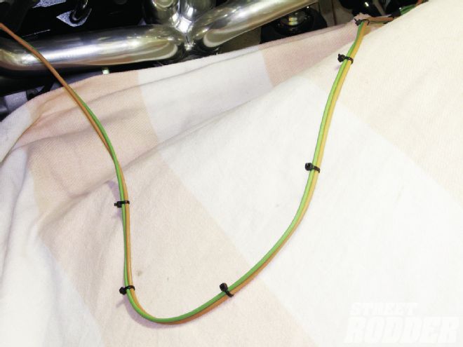 The harnesses were neatly wire tied every 5 to 6 inches; plan on using a number of small wire ties.
The rear section wiring harness was run along the edge of the passenger floor through a grommet-filled hole in the seat riser and out of the floor of the pickup truck cab. Obviously on a coupe, roadster, or sedan you would run the wires through the trunk area. The rear wiring harness consisted of taillight/brake light, license plate light, and the fuel sender gauge wires. Since we are utilizing an electric fuel pump we also included a switched fuel pump wire. Since we were not running a heater (we live in Florida) we used the fused heater wire in the wiring kit as the fuel pump wire.
The fan relay was mounted under the seat and wired per the instructions. We also added an on/off switch on the ground side of the relay. This allows us to manually turn the fan off should we choose to do so during engine maintenance. We chose to run the fan whenever the engine is running; we may add a temperature controlled fan switch at a later date. We also installed a relay and a switch on the fuel pump; this too was mounted under the seat.
A piece of plate stock was formed to match the curve of the dashboard and the American Autowire turn signal toggle switch and the horn button were mounted to that plate. The plate was then mounted to the left of the steering column near the front edge of the dashboard. These switches could have been located on the dashboard, but we wanted to keep the dashboard uncluttered.
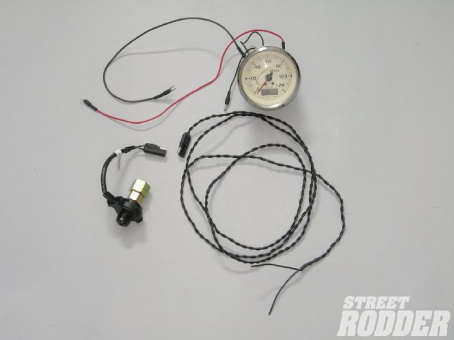 We followed the speedometer installation instructions and twisted the paired wires. Those wires were run in a manner to keep them away from any other wires to avoid interference. A separate ground was also used.
Since we are utilizing an original, 6V Model A horn we purchased a 12V to 6V voltage reducer from Speedway Motors and placed it between the power side of the horn button and the horn, the opposite side of the push-button horn switch was attached to one of our grounding strips.
The turn signal wires from the wiring harness were attached to the American Autowire turn signal toggle switch according to the supplied instructions and we had front and rear turn signals. (Note: Since we are utilizing LED taillights/turn signals we purchased a special turn signal flasher from Speedway Motors that is designed to work with LED turn signals.)
The float rod on the fuel tank sending unit was cut, bent, and installed per the instructions. The rod is cut based on the depth of your fuel tank. The sending unit was then installed in the tank. We elected to run a ground wire from one of the sending unit screws to a chassis ground. This grounded the sending unit as well as the fuel tank.
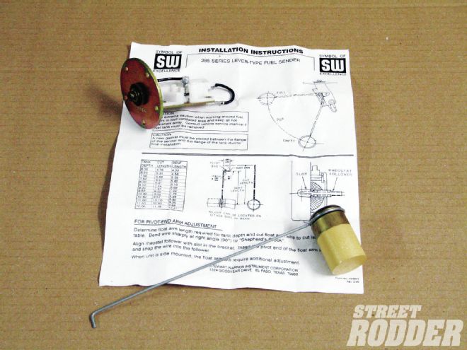 Per the gauge instructions, the fuel gauge sending unit arm was cut, bent, and installed based on the depth of the fuel tank.
The battery circuit was next. Obviously there are various ways to connect and ground a battery. The battery location has a lot to do with the selection. Since our battery is located in the bed of our pickup truck we needed some fairly long cables. We ran a No. 2 cable from the positive side of the battery to the starter solenoid. We then ran No. 2 cable from the negative battery terminal to the battery disconnect switch that we had located on the front of the seat riser. Another No. 2 battery cable was then run from the battery disconnect switch to a good chassis ground. (Note: A good ground consists of an area of metal that is free of rust, corrosion, paint, etc.) We used pre-manufactured battery cables with the correct ends (battery clamp or terminal ends) factory installed; you could also make your own.
Grounding cables and ground wires should always be attached to clean metal areas. Many electrical problems are often traced to poor grounds.
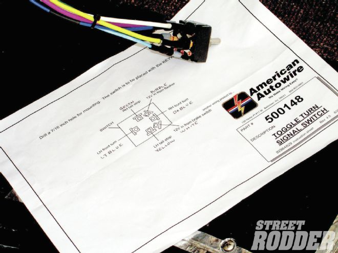 The American Autowire toggle turn signal switch was wired per the instructions. Note that we wrote the color of each wire on the schematic for troubleshooting at a future date, if necessary.
Battery disconnects are an excellent safety device, in addition to a theft deterrent. By interrupting the battery circuit all electrical flow to the system is disconnected. Thus, a short in a wire or an overloaded circuit can’t start a fire while the vehicle is unattended. The battery disconnect location should be at a point at which it can be easily reached by the driver. This allows the electrical circuit to be shut off immediately should something unexpected occur. Battery disconnect switches are available as a simple on/off switch, or on/off switch with a removable key. In addition, you can select a battery disconnect switch with a terminal to allow a power wire to remain on when the switch is in the off position. This allows you to retain various memory selections in a radio or other such devices.
Once all of the wires were run we tested each circuit. Satisfied that all electrical circuits were operating as planned, we covered the various wiring harnesses with a split plastic conduit. This added a professional, finishing touch to the wiring.
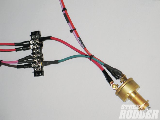 We used terminal strips and jumper strips throughout the wiring system. This allows multiple wires to be fed off of one wire, makes connections easier to trace, and makes for a much neater wiring system.
Throughout the process we generated rough, hand-drawn wiring schematics of the various systems; this will allow us to troubleshoot the electrical system at a later date should something malfunction.
Thanks to today’s wiring kits the task of wiring our street rod was not nearly as tough as it might seem, and we have the satisfaction of being able to say we did it ourselves.