Sometimes, old just feels better. Not that there's anything wrong with the new technology available to car enthusiasts today. It allows us to do things we couldn't even dream about a few short years ago. But there is something about operating a pure mechanical device that brings great satisfaction.
Such was the case with the owner of this early Camaro. Initially, a high-tech EFI-controlled LS with an electronically controlled 480LE were installed. But even with the option of manual shift control, the auto trans—though it worked beautifully and arguably made the car faster—just couldn't bring complete fulfillment. Right away, thoughts of a five- or even a six-speed swap come to mind, but no, this was a time to go back to the basics, a Muncie close-ratio four-speed. Nothing high tech, just grab the handle and do what feels right.
Now everyone knows that GM never put a Muncie behind an LS, so a way was needed to mate those two and also find a simple way to work the clutch around the headers. Keisler Engineering had the solution to both issues with a flywheel, a hydraulic clutch, and a bellhousing that allow an LS to play nice with a Muncie. Classic Industries was called on for the Muncie, as well as the shifter, the linkage, and the pedals to control it.
Parts
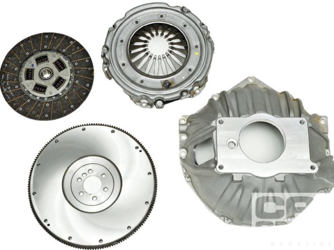
 The key to hooking up a Muncie four-speed to an LS is, of course, a bellhousing that bolts to both. Keisler’s bell is 6.5 inches deep and features thick-wall titanium-aluminum construction. The flywheel is a 168-tooth billet steel version that will handle both 11- and 12-inch clutches. This 11-inch clutch and pressure plate are rated to 550 hp and 500 lb-ft of torque.
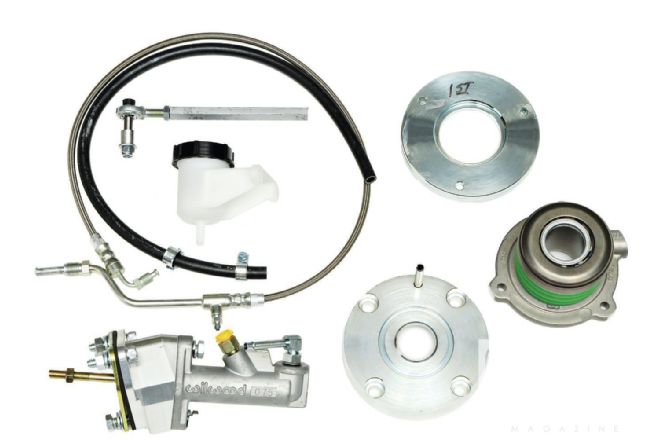 While it may have been possible to fit a standard clutch linkage around the LS headers, a hydraulic clutch will work in all applications. It’s not exactly old school, but it is purely mechanical and the driving experience will be the same. The Keisler kit comes with the throw-out bearing (technically known as a concentric slave cylinder or CSC), master cylinder, reservoir, and hoses. Also included is a replacement front bearing retainer to keep the CSC centered and to prevent it from rotating. Spacers may also be needed to ensure proper bearing clearance or cushion.
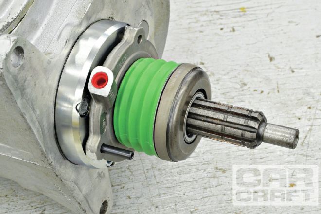
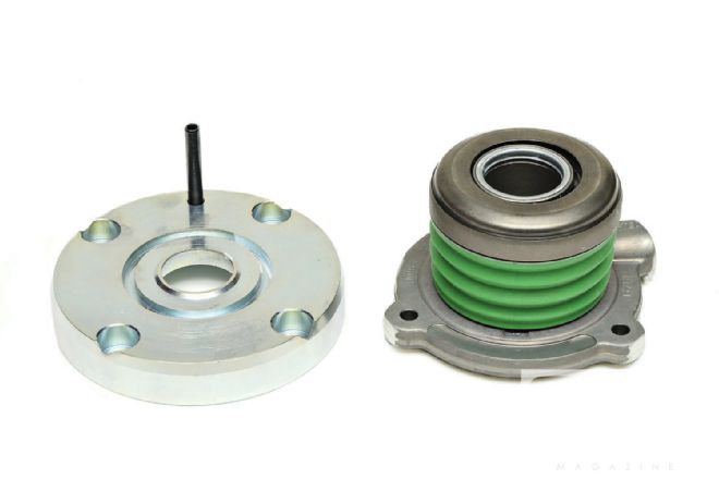 The Keisler hydraulic throw-out bearing or CSC requires a special front bearing retainer to both keep it centered on the input shaft and to prevent it from rotating around the shaft. Note the locating pin at the top of the retainer.
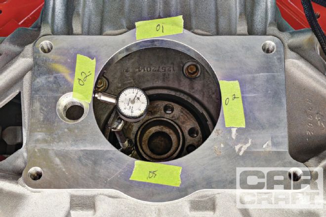 Resist the temptation to just throw it all together and take the time to check the bellhousing runout. Attach a dial indicator to the crank with a magnetic mount and take readings every 90 degrees. Max runout should be within 0.004 to 0.007 inch. Keisler’s CNC-machined bell is very good. This is a nicely built precision part.
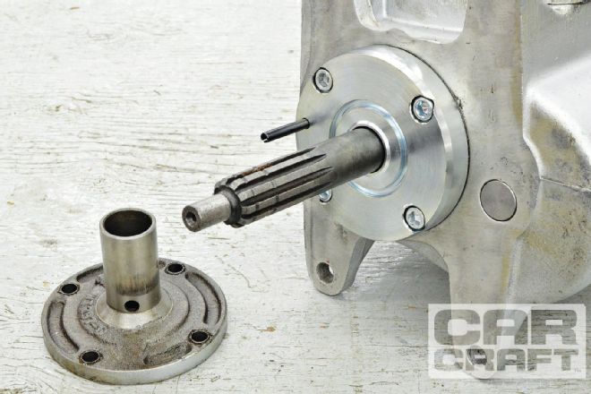
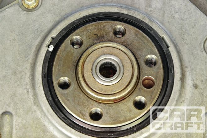
 The Muncie front retainer is replaced with a special Keisler unit that centers the bearing to keep it from riding on the input shaft. Note the pin at the top of the retainer that keeps the bearing from rotating and locates the line fitting toward the clutch arm opening.
 This should go without saying, but how many times have you heard of someone switching from an automatic to a manual and they forget to install the pilot bushing for the input shaft? The bushing is included with the kit.
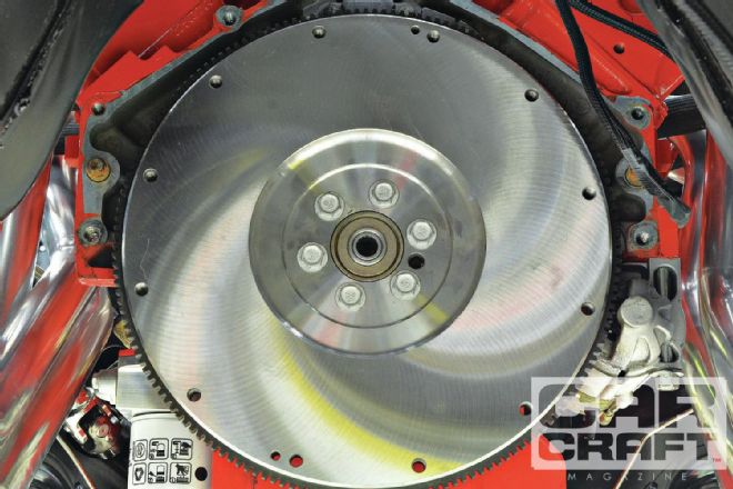 MCR has every new flywheel lightly resurfaced before it is installed. It’s rare, but we’ve seen new flywheels that aren’t flat. That reduces the holding capacity and speeds up the wear on the disc. And don’t forget to use a thread-locker and oil-sealer on the bolts. Remember, LS crank threads are open to crankcase oil. The torque sequence is first 15, then 37, and lastly 74 lb-ft on the bolts.
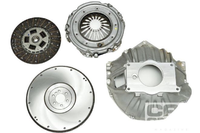
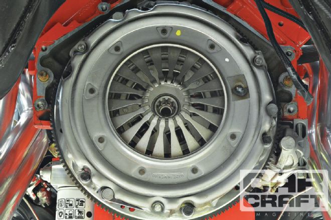 The clutch is a Sach’s Borg & Beck high-performance copper organic single disc with a nodular iron diaphragm pressure plate. It is rated at 550 hp and 500 lb-ft of torque.
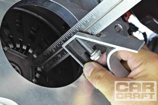 Setting up the proper clearance or, more accurately, the proper cushion for the bearing is critical for correct operation. This bearing is designed to be in constant contact with the pressure plate fingers—by the way, this unit is not compatible with most three-finger pressure plates and, in fact, is mostly compressed by the fingers when at rest. The procedure for measuring the cushion is pretty straightforward. Start by measuring the distance from the transmission mounting face to the contact surface of the pressure plate fingers. Subtracting 2.52 inches (per Keisler instructions) from that measurement equals the amount of cushion there is in the bearing. Another way to look at it is this number is how much farther the bearing can be compressed before it bottoms out and at that point would not fully release the clutch. In our case, the finger to mounting face measurement was 3.17 inches. Subtracting 2.52 yields 0.65 inches, which is way outside the 0.125 to 0.375 range that’s required. The bearing has about
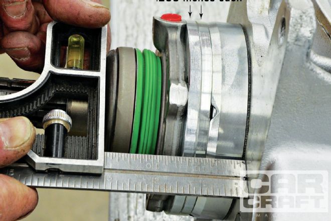 Fortunately, Keisler makes 0.250-inch spacers available for just such occasions. Adding two of those adds 0.500 inch to the standard 2.52 inches, which then yields 3.02 inches. Subtract 3.02 (fully compressed bearing plus spacers) from 3.17 (distance from fingers to mount face), and we get 0.150 inch, which is now within range. The 1⁄8-inch minimum cushion is needed to compensate for heat expansion and clutch wear. If it turns out you don’t have enough cushion without any spacers, Keisler makes a 0.250-inch bellhousing-to-transmission spacer that should allow you the room you need. Or if you just need a little room, some more material could be removed from the surface of the flywheel. Since this bearing has a total travel of approximately 9⁄10 inch (minus the cushion, of course) and most clutches release within 1⁄2 inch of travel, there is now plenty of extra travel to keep the bearing from overextending. The guys at MCR took the extra step of measuring the bearing-to-trans mounting face with the bearing full
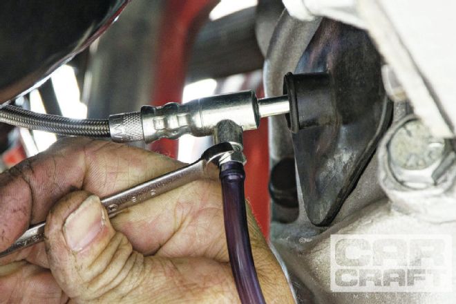
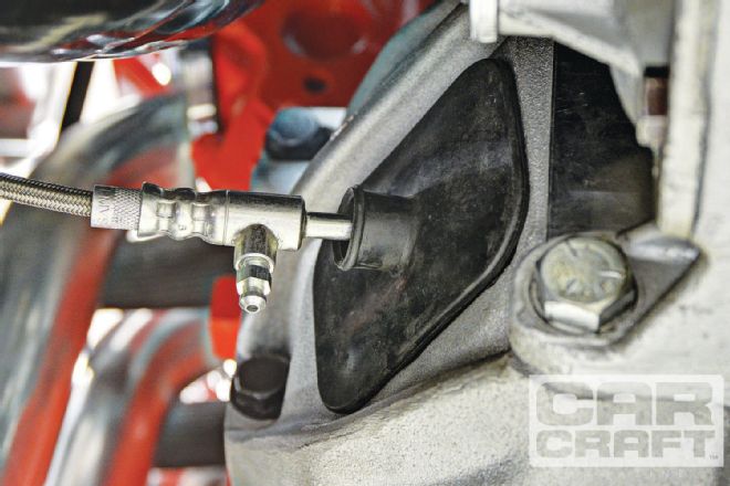 It should be noted that Keisler recommends installing the bellhousing and transmission, with the hydraulic line attached to the CSC, as one unit. The guys at MCR, however, were constrained both by habits and the desire to avoid any chance of damaging the line during the installation, so the line was installed and tightened via the clutch fork opening after the trans was in place. But note this: Extreme care must be taken to avoid cross-threading the fitting.
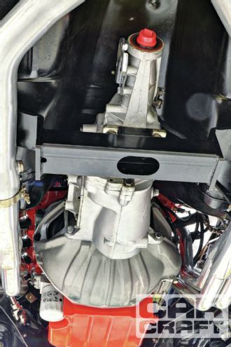 The trans crossmember is from Detroit Speed and provides more clearance for the exhaust than a factory crossmember would.
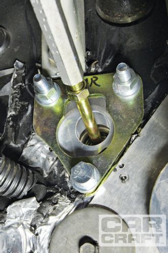
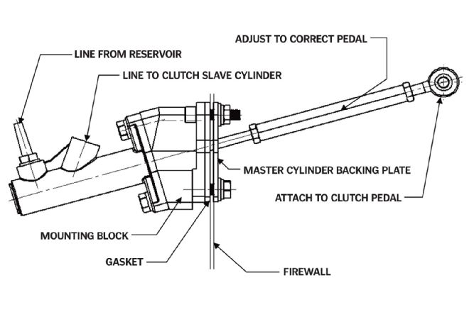 The clutch master cylinder bolts over the existing clutch rod hole through the firewall. As seen here, the angle of the pushrod should be kept as close to the centerline of the master cylinder as possible.
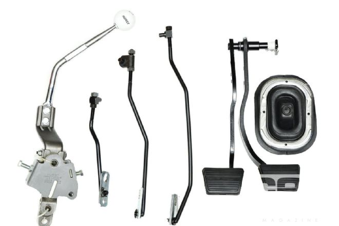 Classic Industries supplied a new Hurst shifter, linkage, boot and clutch, and brake pedals to go with its close-ratio version of this Muncie.
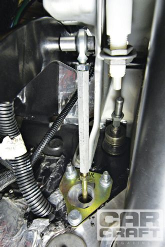
 It is difficult to see under the brake master cylinder and Hydroboost system, and it certainly would have been much easier to install the clutch master cylinder by removing the Hydroboost system first, but MCR wanted to be sure that there was adequate clearance for it and the fluid lines before mounting it to the firewall.
 MCR used the master cylinder backing plate as a template for drilling the mounting holes through the firewall. If you choose to remove your brake master, this could more easily be done from the engine side of the firewall.
 Near-perfect pushrod alignment was achieved using the lower of the two holes that were already in the clutch pedal arm. Adjust the pushrod to get whatever pedal height you prefer, but be sure that the master cylinder is not being prevented from fully returning to its home position. The usual rubber pedal stop at the top of the pedal travel is not required since there is no pedal “free play” before the pedal engages the throw-out bearing. This system is engineered for installation without the need to consider pedal ratios. As long as the proper cushion has been set, there should be no chance of over-traveling the pressure plate or over-extending the bearing.
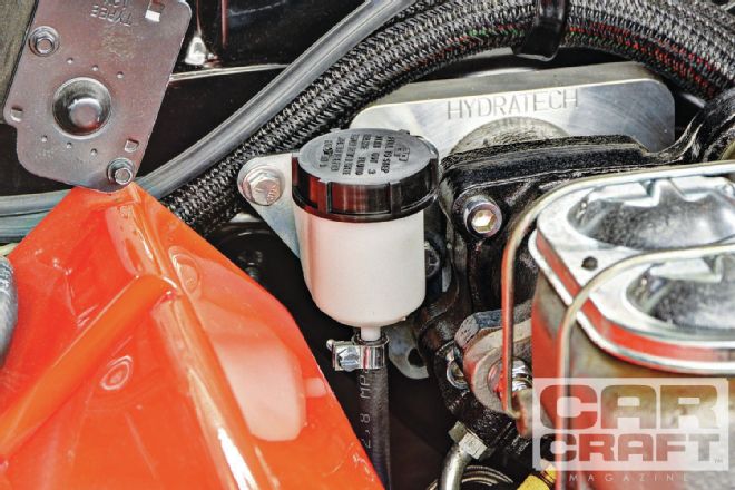 The kit comes with a bracket to mount the fluid reservoir to two of the bolts of your brake master cylinder. You can mount it anywhere that’s convenient. Just be sure to keep the rubber hose away from the headers or anything that it could potentially rub against.
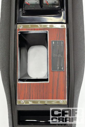 A new four-speed console with gauges was obtained from Classic Industries to finish the interior look.
 Bleeding the system is very much like bleeding brakes. Fill the reservoir with fluid and open the bleeder screw. When the drip becomes a steady stream, close the bleeder and then have a buddy depress the clutch while you open the bleeder. When the clutch pedal reaches the floor, close the bleeder and release the clutch. The pedal may need to be manually pulled up from the floor until at least most of the air is out because it’s the pressure from the clutch fingers depressing the throw-out bearing that pushes fluid back against the master cylinder that raises the clutch pedal. When there is air in the system, that pressure just compresses that air. Because the bleeder screw is not at the end of the fluid path like a normal wheel cylinder, it might be necessary to bleed the system again after a short period of use to remove any last remnants of air from the system. End