Bomber-style seats have been used in street rods since the '40s, and "back in the day" most of these came from military surplus yards. Lately these seats have become enormously popular, and now we are seeing a lot of newly constructed bomber seats in cars (such as the ones from Frank Wallic, a regular contributor to STREET RODDER). They've always been considered kool, and for good reason; they're practical, lightweight, and they give a car a purpose-built look with an aircraft flavor.
I've loved the look of bomber seats for years, and recently decided to build a pair for my aluminum-bodied roadster. I looked closely at the various designs I've seen, and I identified several features I wanted to incorporate in my own seats. While a lot of true aircraft seats have a flat back, I much prefer the look of a rounded back. Most true aircraft seats are riveted together, but some seats, which have a lot of curved components, are welded. I wanted a lot of curves, so I designed a bottom to be welded into place, but I like the look of rivets very much, so I decided to use rivets to attach the reinforcing edge of the seat. Last and perhaps most importantly, I liked the look of the seats with lots of holes. Of course, in the aircraft world where these seats were developed, holes were used to shave valuable weight from each part. The weight issue is not so important for a street-driven car, but man, do I like the look of holes. So early on, my plan was to design a seat that would have just as many holes as possible.
I recently got a set of the Mittler Brothers Punch and Flare tools. These are made in seven sizes, from 1 inch to 3 inches in diameter, and they are cleverly designed to both punch the hole and flare the edge in one operation. I wanted to use every size for my seat, and my design is based on how these progressive hole sizes could be used in a pleasing pattern.
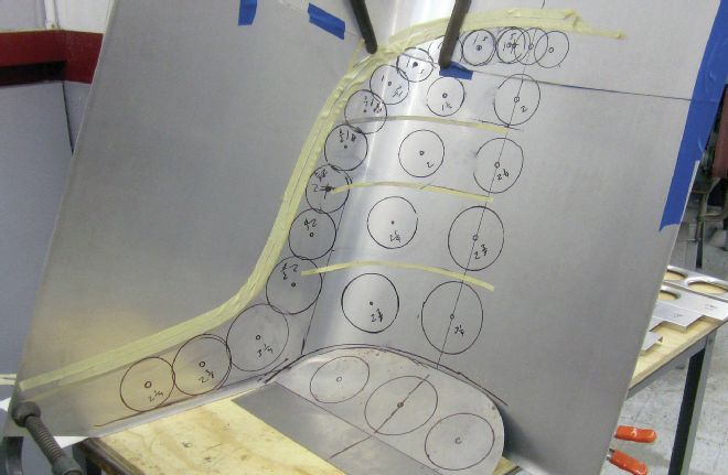
I hate to invest a lot of time in a project without knowing for sure if I will like the look of the finished product, so I took the time to do a quick, full-size mockup of one half of the seat, based on my initial design. When I saw this mockup I realized that I wanted to make many small adjustments in the hole sizes and placement, and I saw an opportunity to use even more holes. I made a second mockup incorporating these changes, and this one looked great, so I used it to make the chip board master pattern for the seat. I align this pattern on the centerline of the metal blank for the seat back, so I can flip it over to mark each side. This simplifies the pattern, and ensures the seat back will be symmetrical.
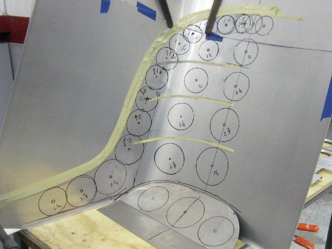
Next, I cut a rectangle of 0.063-inch thickness 3003 H-14 aluminum sheet to size. I put a centerline on the panel, and using my chipboard pattern, I laid out the edges of the seat, and the center for each hole. Next, I drilled 1/8-inch holes in the center of each hole location.
While the seat back could have been bent freehand, since I plan to make at least two of these seats, I decided to make a simple bending fixture to ensure that the bends on each side are identical, and will be identical for all future seats I make. The fixture was made from 3/4-inch MFD, and since sheetmetal has a lot of "spring back," I had to experiment a little to find the proper shape for the form that would allow the aluminum to be bent tightly against it and then spring back to be the shape I wanted. I also had to plan ahead with the shape of the fixture so the first bend won't collide, hampering the second bend.
1. I designed this seat from scratch, incorporating design features I liked on several other seats I've seen. One of the first steps is doing a rough layout of the allover shape and hole placement on some aluminum sheet.
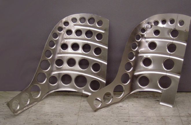
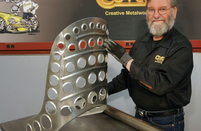
2. Next, I made a full-sized mockup of one half of the seat. After seeing this mockup, I decided that more holes would be better, so I made a second mockup (seen on the left).
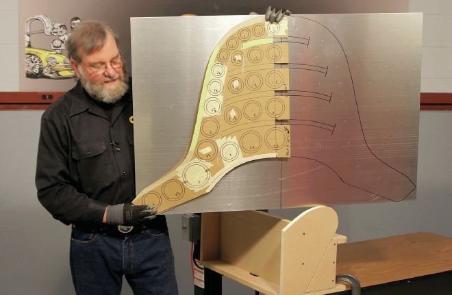
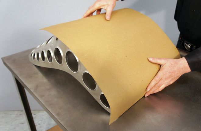
3. Once I was satisfied with the design, I made an accurate half-pattern from chip board, and laid out both sides of the seat from the centerline. This will ensure that the seat is symmetrical.
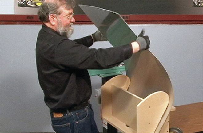
4. I could have bent the seat back freehand, but I made a simple MDF bending fixture so I could make any number of seats and know they would all be exactly the same shape.
 5. The fixture is designed to over-bend the metal, so it springs back to the exact shape I want. This took a little trial and error, but now I can make repeated bends with accuracy.
5. The fixture is designed to over-bend the metal, so it springs back to the exact shape I want. This took a little trial and error, but now I can make repeated bends with accuracy.
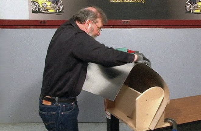
6. The second bend is made in the same way. My fixture is configured so that the first bend would not interfere with the second. Again, this took a little trial and error.
7. The sequence of operations is very important. First, the bending is done. Second, the beads are made. Third, the holes are punched and flared. Last, the edges are trimmed.
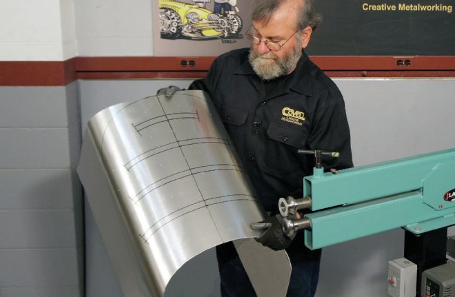
8. I used a 3/4-inch beading die on the seat back. Note the layout lines that I used to guide the dies so the beads would be positioned correctly and end at the right place.
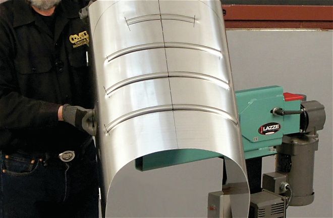
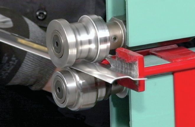
9. Here you can see the crisp beads made by the Lazze beading machine.
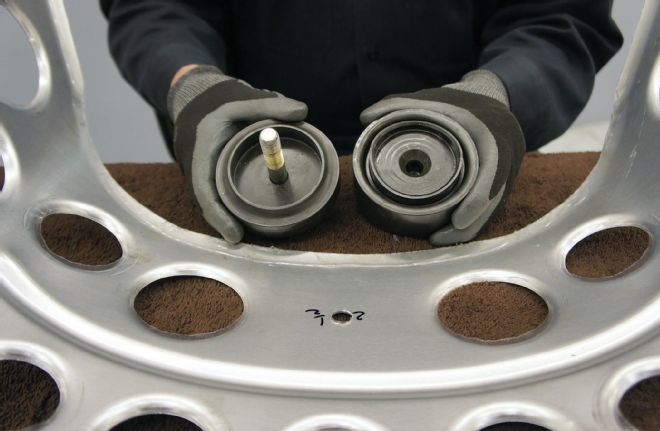
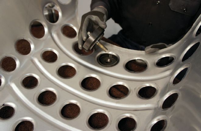
10. This is the Mittler Brothers Punch and Flare Tool. This clever device punches the hole and flares the edge in one operation. These come in seven sizes, from 1 to 3 inches, and I used them all.
It's important to think about the sequence of operations for a complicated part like this. If I had put the beads and flared holes in the sheet first, the bending would not have come out smoothly.
So, with the seat back curved, I was ready to put the beads on the panel. The beads were designed as curved lines, to fit neatly between the curved rows of flared holes, and my pattern showed the exact location of each bead. Again, the sequence is important; if I had made the holes first, the flared edges would have interfered with the dies used for beading.
You need a deep-throat beading machine for a panel this size. I used my 18-inch throat Lazze machine, and even with a machine this size I had to approach the panel from two different directions to keep the edge of the part from bumping against the frame of the machine.
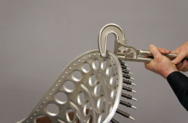
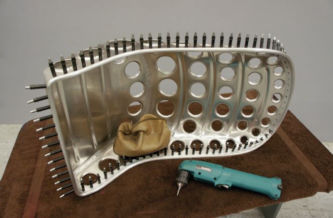
With the beads completed, I was ready to make the holes. The punch and flare tools are operated by tightening a 1/2-inch bolt that draws the two halves together, so 1/2-inch holes were made for each hole location. I used a Rotabroach for this, but a step-drill would work, too. Next, I started making all the flared holes. With dozens of holes to make, I decided to use a 1/2-inch air impact gun to speed the work. A note of caution here; it's a really good idea to use a felt-tipped marker to write the size of each hole on the metal blank. (Don't ask how I know this!)
I knew that both the beading and the hole flaring would take some of the curvature out of the seat back, so I re-bent the panel freehand to restore the proper contour. It's important to keep the blank rectangular up to this point, since you'll need the leverage provided by the extra material to bend the whole sheet evenly.
With the shape corrected, it was time to trim the edges to final size. I wanted the seat bottom to meet the seat back with a radiused edge rather than a sharp corner, so I used rounding-over dies on a beading machine to put a 1-inch radius 45-degree curl on the bottom edges of the seat back. This could be done with a hammer and dolly, too, but the beading machine makes this operation quick and accurate.
Next I used chip board to make a pattern for the seat bottom. I wanted to get the width right, but I allowed extra material both front and back to give me a little wiggle room for fitting it to the seat back. Thinking about the sequence of operations, I put the beads in the panel first, and then curled the edges while it was still flat.
To make the bends, I made a simple radius die from exhaust tubing, which was held to my workbench with clamps. Clamping the metal against the fixture flattened the curled edge in the corners, but that was easy to correct later. I used a bevel protractor to measure the angle of each bend (note that the front angle is different from the back).
With the seat bottom bent, I positioned it against the seat back and marked the edges for trimming to the final size. The curved back edge was curled with the rounding-over dies, and the panels were tack-welded together. After using a hammer and dolly to get perfect alignment at the joint, they were finish welded with my Miller Dynasty 200 TIG welder.
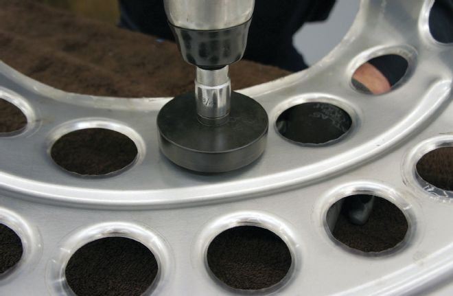
11. The dies are tightened together with a 1/2-inch bolt. Since I had so many holes to make, I used an impact gun to speed the job. Look at the beautiful holes these dies make!
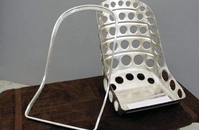
12. Flaring the holes takes some of the curve out of the seat back, and I left the panel's edges untrimmed so I would have enough leverage to re-bend the part back to the right contour.
13. After correcting the shape, the edges of the panel were trimmed to the finished profile, and I put a 45-degree curl on the edges where the seat bottom will attach.
14. I'm using a piece of chip board to make a pattern for the seat bottom. I want to get the width right, but I'm leaving extra material front and back so I can trim it to size after bending.
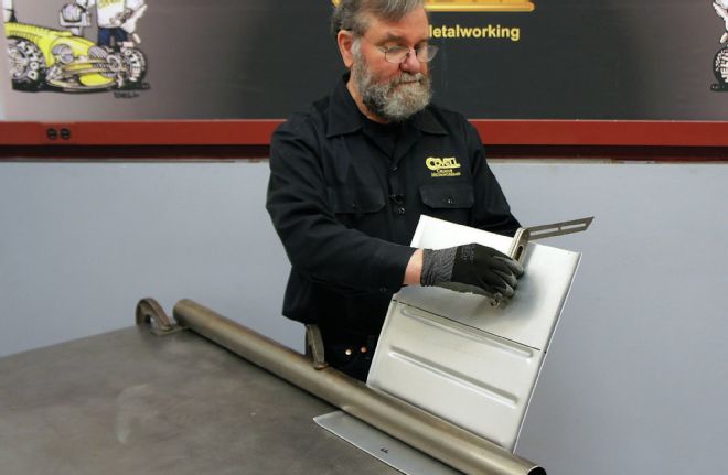
15. I made a simple bending die from a piece of exhaust tubing. The seat bottom gets two bends, and I'm checking the angle of the first bend here with a bevel protractor.
16. Here's the seat bottom trimmed to size, beaded, and tack-welded to the seat back.
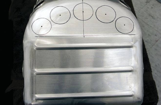
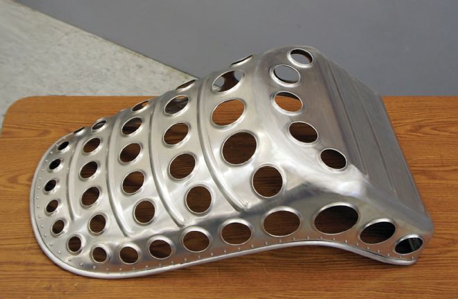
17. The seat bottom is finish welded and smoothed here, and I'm doing the final layout for the holes. Note how I'm keeping the rows of holes in a consistent pattern.
18. The seat has a reinforcing strip riveted to the edge. Here I'm using a large beading die to start forming a strip of aluminum into the preliminary shape.
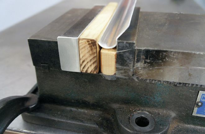
19. I discovered that using a large flat-jawed vise is better than hammering for tightening the curl on the edge of the strip. I made a wooden cover for the vise jaw to help reduce marking.
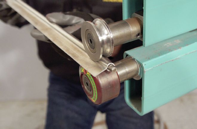
20. With the part formed into a “question mark” shape, I inserted a length of 5/16-inch aluminum round bar, and squeezed the sheetmetal tightly against it—first with the vise and then the beading machine.
The seat edging was next. This was made from aluminum sheetmetal wrapped around a 5/16-inch-diameter 6061 T6 aluminum round bar. I started by using a die on the Lazze machine designed to make the beltline on a '33 Ford. I cut several strips of aluminum 3-feet long and ran them through this die set, leaving a 1-inch-wide flange on one side. I wanted to turn this profile into a “question mark” shape and presumed I would do this by hammering, but I found that I could form the metal faster and more smoothly by squeezing it in a 6-inch flat-jawed vise. Once I had the curved part worked down to about 1/2-inch-diameter curl, I inserted a 3-foot length of the round aluminum bar, and used the vise to squeeze the sheetmetal down against it. To get the final tightness of the sheetmetal against the solid bar, I used the beading machine with the female half of a beading die on the top, and a urethane die on the bottom. I ran each piece through the machine twice; once right-side up, and one upside down. This finished off the three blanks for the edging very nicely.
Now the edging had to be contoured to match the seat, and I annealed the strips to ease this process. It's always best to do the most difficult operation first, and in this case that was the tight-radius bends on the two front corners of the seat. I bent these corners around a piece of heavy-wall tubing.
I used a shrinker and stretcher for the more gradual curves on the edging. Using these tools, it's easy to make the metal bend in one plane, but the center portion of the edging needs to have a spiral bend, and this was challenging. I accomplished this by doing the work with the shrinker first, then clamping the edging to a large-diameter piece of tubing, and hand bending it in the other plane. This took a bit of back-and-forth tweaking, but I finally got the shape dialed-in pretty well.
With the edging properly shaped, I clamped each piece into place and laid out the rivet holes. I decided to use 5/32-inch rivets, since I like the head diameter of these, but I used 1/8-inch holes for the initial layout so any slight misalignment could be dealt with later. I used a Whitney hand punch for all the holes (although they could be drilled), and then held each segment into place with Clecos, and marked the ends of each segment for trimming. The ends were cut, the parts were re-assembled on the seat, and the joints were tack-welded. After checking the fit one last time, the joints in the edging were finish-welded and sanded smooth. I put a lot of time into finishing this edging strip, removing all the marks that the shrinker and stretcher made, and smoothing the welded joints to perfection. Any cleaning up on this part has to be done before it's riveted into place.
The edging was positioned back on the seat, and I put 1/8-inch Clecos in every fourth hole. Next, I drilled through each hole location with a 5/32-inch drill bit. This match-drilling ensures perfect alignment for the rivet holes. With the drilling completed, the edging was removed, and both the edging and seat were very carefully deburred. This is a crucial step as even a tiny burr around a rivet hole will prevent the metal pieces from joining tightly when the rivet is set.
Next, I re-assembled the edging on the seat using a 5/32-inch Cleco in every hole, and I was ready to start the riveting. Rivets are often set with a pneumatic riveting gun, but I wanted to try using a rivet squeezer, so I ordered one online, and I am very impressed with the speed and quality of the riveted joints it produces! There are about 86 rivets in this seat, and every one needs to be properly done, so the rivet squeezer was joy to use.
The riveted edging was truly the finishing touch for this seat. It adds a lot of strength, gives the edge of the seat a smooth, easy-to-handle surface, and it adds a lot of visual appeal to the design. A seat like this would be a good project for an intermediate or advanced metalworker, and you are welcome to contact Ron Covell if you would like a set of patterns of this seat, or a DVD that shows its construction.
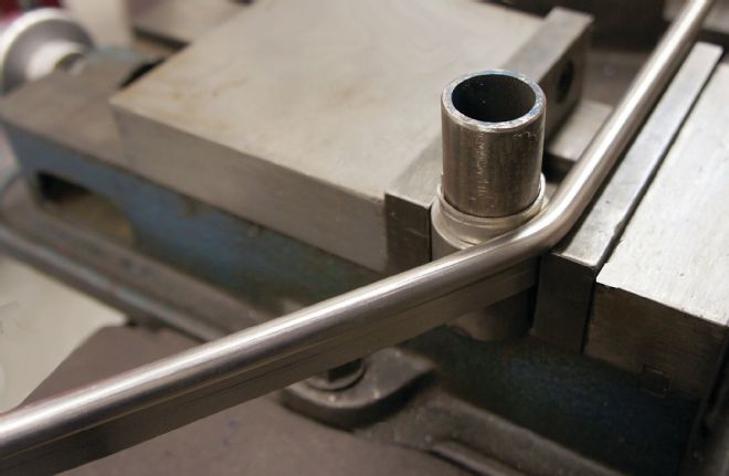
21. The seat edging required several bends, and I made a simple fixture to make the tightest and most difficult bend first. Notice how I'm using the vise to hold the edging against the fixture.
22. The edging was made in three sections, and much of the forming was done with a shrinking and stretching machine. Here I'm checking the fit against the seat.
23. After each piece of the edging was properly fitted, they were welded together and smoothed. In this shot you can see the 1/8-inch pilot holes for the rivets.
24. The edging is clamped to the seat, and each rivet hole is match-drilled, then the parts are disassembled and deburred. Here the parts are reassembled and held with Clecos.
25. I'm using a rivet squeezer to set the 5/32-inch universal-head aluminum rivets. There are about 86 rivets on the seat, and the rivet squeezer really speeded the job.
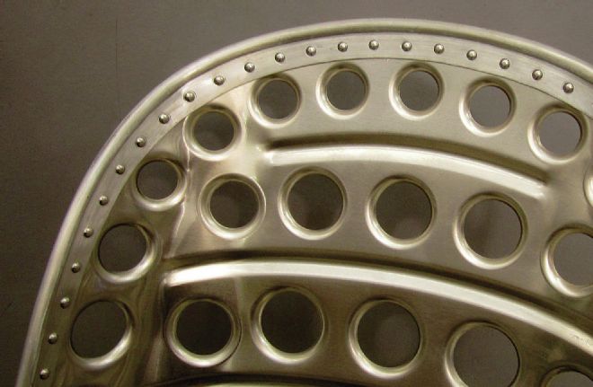
26. You can see how the edging not only strengthens the seat, but the uniform rivet spacing gives it a design element, too.
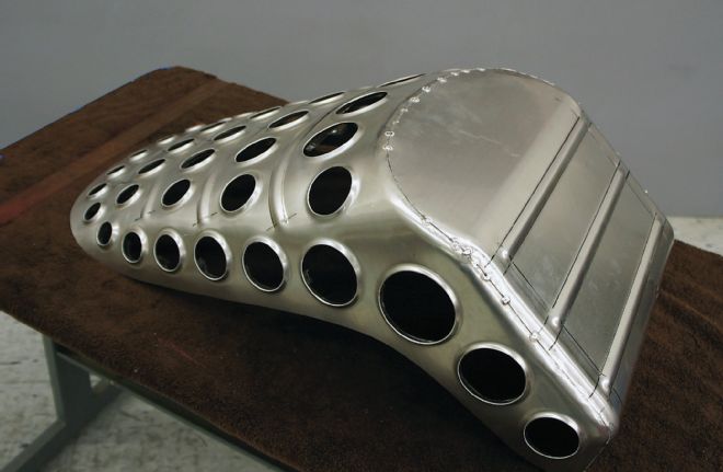
27. Here's a bottom view of the finished seat. Since this seat won't be painted, I took extreme care to prevent the metal from getting marred from handling.
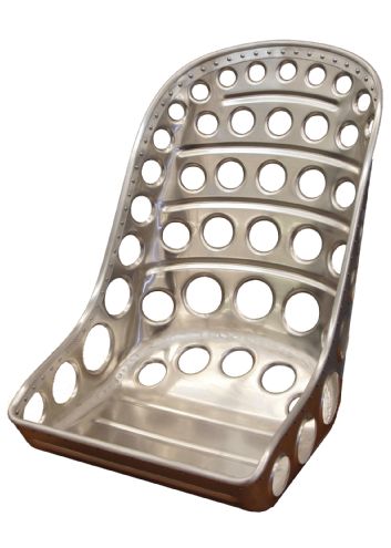
28. And here's the front view. I must say, I am extremely pleased with the finished product, and I would encourage any of our experienced readers to try their hand at making their own bomber seat.